[level-membership-for-neurosurgery-category]
Chapter 34 Lateral Percutaneous Interspinous System for the Treatment of Lumbar Stenosis
One of the main problems of degenerative spine disease is a narrowed spinal canal [1]. The pathologic progression begins with degenerative changes within the disc, which eventually lead to a loss of disc height. Resultant instability may worsen the spondylosis by inducing facet joint hypertrophy [2]. Furthermore, hypertrophy and buckling of the ligamentum flavum, particularly during extension, contribute to a reduction in the size of the thecal sac. This reduction limits the space available for the cauda equina, so the patient experiences symptoms of neurogenic claudication. The patient experiences relief in flexion [3].
Traditionally, spinal fusion has been the mainstay of surgical approaches for the management of low back pain or lumbar instability. Furthermore, there is some evidence that fusion may increase the biomechanical stresses imposed on the adjacent segments that could lead to transitional disease, which may occur earlier in patients with instrumented fusion [4].
Dynamic stabilization is a system that favorably alters the movement and load transmission of a spinal motion segment, without fusing the segment [5,6]. In other words, such a system would restrict motion in the direction or plane that produces pain, or painful motion, but would otherwise allow a full range of motion [7–10,12].
An interspinous distraction device was first described by Dr. Fred L. Knowles more than 50 years ago. Dr. Jacques Senegas was one of the first innovators in this area, and since his work [12], many new interspinous devices have been developed for ideal performance and clinical results [13–15].
Currently a variety of interspinous process implants are available [16] with different characteristics in material (allograft, polyetheretherketone [PEEK], titanium, elastomeric compounds, etc), kinematic features (static and dynamic), and surgical technique (open and percutaneous techniques) but share the goal of achieving some distraction between two vertebral bodies in order to accomplish the following goals:


These devices help open the spinal canal diameter to relieve the patient’s neurogenic symptoms. However, upon insertion many interspinous devices require sacrifice of the integrity of the supraspinous ligament, paraspinous muscles, and fascia. These structures are important elements that maintain spinal stability, so their preservation inherently stabilizes the motion segment [7–11,17].
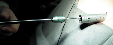
New technology now allows insertion of interspinous process implants via a minimally invasive lateral percutaneous approach that involves shortened surgery time, hospital stay, and rehabilitation and allows a faster return to daily activities. The RENEGADE interspinous implant (Globus Medical, Audubon, PA) is generally barbell shaped with a fluted conical insertion end to facilitate distraction and a central portion that rests on the spinous processes. The unique design allows for percutaneous insertion and simultaneous distraction of the interspinous space (Fig. 34-1).


Contraindications
Insertion of a lumbar interspinous implant is contraindicated by the following conditions:


Advantages
Advantages of percutaneous interspinous process implantation over open implantation are as follows:


Surgical technique
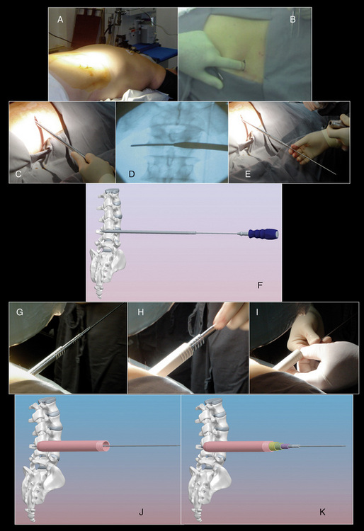
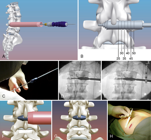
The procedure for implantation of the RENEGADE lumbar interspinous device is as follows:


Conclusion
CASE STUDY 34.1
A 76-year-old man presented with a history of progressive low back pain and bilateral neurogenic claudication. His symptoms were relieved on flexion. The decision was made to implant a lumbar interspinous device. Preoperative radiographic and magnetic resonance imaging evaluations are shown in Figure 34-4.
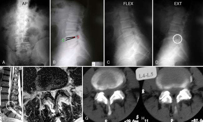
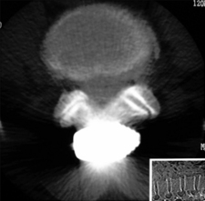
Figure 34–4 Case Study 34.1: Preoperative radiographs (top) and magnetic resonance images with computed tomographic images (bottom) from 76-year-old man with neurogenic claudication. (A) multiple degenerative spur changes in vertebral bodies on AP fluoroscopic view; (B) The arrows and lines demonstrate a loss of posterior intervertebral disc height on lateral view; (C and D) The dynamic x-ray view shows that the circle indicates narrowing of the L4 foramen in extension; (E) The sagittal MRI also shows that the circle indicates narrowing of the L4 foramen in extension; (F) The axial views show spinal canal stenosis; (G and H) The CT scan demonstrates degenerative facet joints which are hypertrophied. AP, anteroposterior; EXT, extension; FLEX, flexion.
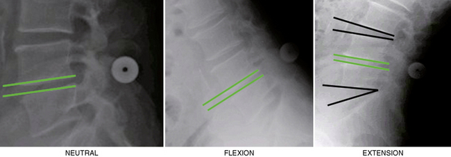
The interspinous implant was positioned in the interspinous space at L4-L5. The patient experienced a significant reduction in pain immediately postoperatively. Increased posterior disc height was demonstrated at the 6-week follow-up evaluation (Fig. 34-5). The L4 neural foramen was opened in extension, similar to the neutral position (Fig. 34-6). Postoperative computed tomography showed the implant centrally placed at the base of the spinous process (Fig. 34-7). The vertebral end plates remained parallel in extension and flexion (Fig. 34-8), and the foraminal height was maintained.
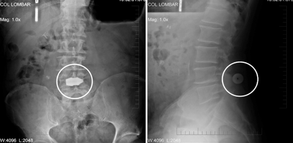
Figure 34–5 Case Study 34.1: Radiographs obtained 6 weeks postoperatively. Left, Anteroposterior view shows central positioning of the device at L4-L5 (circle). Right, Lateral view demonstrate the implant lying at the base of the spinous processes (circle).
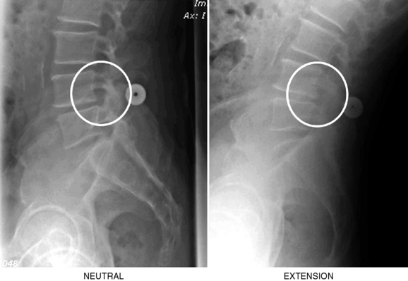
Figure 34–6 Case Study 34.1: Neutral and extension lateral radiographs obtained 6 weeks postoperatively show the L4 neural foramen opened in extension, similar to the neutral position.
CASE STUDY 34.2
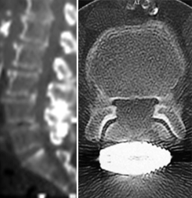
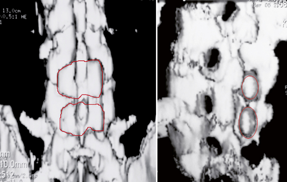
An 82-year-old woman presented with low back pain and weakness in both legs when walking a distance of 100 meters. Her symptoms decreased in flexion. Preoperative radiographs and computed tomography scans are shown in Figure 34-9. Interspinous implants were placed at L3-L4 and L4-L5. The patient’s claudication symptoms resolved postoperatively. Radiographs demonstrated opening of the foramen (Fig. 34-10). Postoperative computed tomography scans showed correct device positioning, which allowed an increase in spinal canal diameter (Fig. 34-11). Three-dimensional computed tomography scans also showed correct device positioning, widened foraminal openings, and the preserved supraspinous ligament (Fig. 34-12).
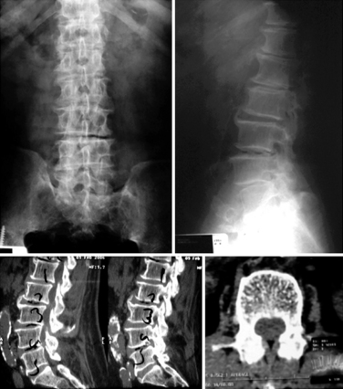
Figure 34–9 Case Study 34.2: Preoperative radiographs (top) and computed tomography scans (bottom) from an 82-year-old woman show foraminal and central stenosis. Her symptoms improved upon flexion.
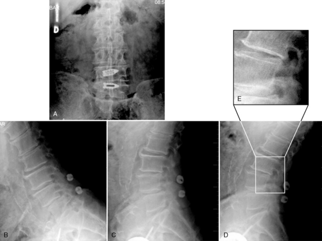
Figure 34–10 Case Study 34.2: Postoperative radiographs. Proper position of implants on fluoroscopic AP view (A) and lateral views (B, C and D), A zoomed-in view of the open foramen (E, right upper). The patient’s claudication symptoms have resolved.
1 Zucherman J.F., Hsu K.Y., Hartjen C.A., Mehalic T.F., Implicito D.A., Martin M.J., et al. A multicenter, prospective, randomized trial evaluating the X STOP interspinous process decompression system for the treatment of neurogenic intermittent claudication: two-year follow-up results. Spine (Phila Pa 1976. 2005;30(12):1351-1358.
2 Fuchs P.D., Lindsey D.P., Hsu K.Y., Zucherman JF., Yerby SA. The use of an interspinous implant in conjunction with a graded facetectomy procedure. Spine. 2005;30:1266-1272.
3 Lee J., Hida K., Seki T., Iwasaki Y., Minoru A. An interspinous process distractor (X STOP) for lumbar spinal stenosis in elderly patients: preliminary experiences in 10 consecutive cases. J Spinal Disord Tech. 2004;17:72-77.
4 Swanson K.E., Lindsey D.P., Hsu K.Y., Zucherman J.F., Yerby S.A. The effects of an interspinous implant on intervertebral disc pressures. Spine. 2003;28:26-32.
5 Wiseman C.M., Lindsey D.P., Fredrick A.D., Yerby S.A. The effect of an interspinous process implant on facet loading during extension. Spine. 2005;30:903-907.
6 Lindsey D.P., Swanson K.E., Fuchs P., Hsu K.Y., Zucherman J.F., Yerby S.A. The effects of an interspinous implant on the kinematics of the instrumented and adjacent levels in the lumbar spine. Spine. 2003;28:2192-2197.
7 Richards J.C., Majumdar S., Lindsey D.P., Beaupré G.S., Yerby S.A. The treatment mechanism of an interspinous process implant for lumbar neurogenic intermittent claudication. Spine. 2005;30:744-749.
8 Neumann P., Wang Y., Kärrholm J., Malchau H., Nordwall A. Determination of inter-spinous process distance in the lumbar spine. Evaluation of reference population to facilitate detection of severe trauma. Eur Spine J. 1999;8:272-278.
9 Dickey J.P., Bednar D.A., Dumas G.A. New insight into the mechanics of the lumbar interspinous ligament. Spine. 1996;23:2720-2727.
10 Shepherd D.E., Leahy J.C., Mathias K.J., Wilkinson S.J., Hukins D.W. Spinous process strength. Spine. 2000;25:319-323.
11 Kroeber M., Unglaub F., Guehring T., Nerlich A., Hadi T., Lotz J., et al. Effects of controlled dynamic disc distraction on degenerated intervertebral discs: an in vivo study on the rabbit lumbar spine model. Spine. 2005;30:181-187.
12 Senegas J., Etchevers J.P., Vital J.M., Baulny D., Grenier F. Recalibration of the lumbar canal, an alternative to laminectomy in the treatment of lumbar canal stenosis. Rev Chir Orthop Reparatrice Appar Mot. 1988;74(1):15-22.
13 Anderson P.A., Tribus C.B., Kitchel S.H. Treatment of neurogenic claudication by interspinous decompression: application of the X STOP device in patients with lumbar degenerative spondylolisthesis. J Neurosurg Spine. 2006;4(6):463-471.
14 Guizzardi G., Petrini P., Fabrizi A.P., et al. The use of DIAM (interspinous stress-breaker device) in the DDD: Italian multicenter clinical experience. New York, New York: Spinal Arthroplasty Society, 2005.
15 Bono C.M., Vaccaro A.R. Interspinous process devices in the lumbar spine. J Spinal Disord Tech. 2007;20:255-261.
16 Christie S.D., Song J.K., Fessler R.G. Dynamic interspinous process technology. Spine. 2005;30:S73-S78.
17 Guehring T., Unglaub F., Lorenz H., Omlor G., Wilke H.J., Kroeber M.W. Intradiscal pressure measurements in normal discs, compressed discs and compressed discs treated with axial posterior disc distraction: An experimental study on the rabbit lumbar spine model. Eur Spine J. 2006;15:597-604.
[/level-membership-for-neurosurgery-category][not-level-membership-for-neurosurgery-category]
Chapter 34 Lateral Percutaneous Interspinous System for the Treatment of Lumbar Stenosis
One of the main problems of degenerative spine disease is a narrowed spinal canal [1]. The pathologic progression begins with degenerative changes within the disc, which eventually lead to a loss of disc height. Resultant instability may worsen the spondylosis by inducing facet joint hypertrophy [2]. Furthermore, hypertrophy and buckling of the ligamentum flavum, particularly during extension, contribute to a reduction in the size of the thecal sac. This reduction limits the space available for the cauda equina, so the patient experiences symptoms of neurogenic claudication. The patient experiences relief in flexion [3].
Traditionally, spinal fusion has been the mainstay of surgical approaches for the management of low back pain or lumbar instability. Furthermore, there is some evidence that fusion may increase the biomechanical stresses imposed on the adjacent segments that could lead to transitional disease, which may occur earlier in patients with instrumented fusion [4].
Dynamic stabilization is a system that favorably alters the movement and load transmission of a spinal motion segment, without fusing the segment [5,6]. In other words, such a system would restrict motion in the direction or plane that produces pain, or painful motion, but would otherwise allow a full range of motion [7–10,12].
An interspinous distraction device was first described by Dr. Fred L. Knowles more than 50 years ago. Dr. Jacques Senegas was one of the first innovators in this area, and since his work [12], many new interspinous devices have been developed for ideal performance and clinical results [13–15].
Currently a variety of interspinous process implants are available [16] with different characteristics in material (allograft, polyetheretherketone [PEEK], titanium, elastomeric compounds, etc), kinematic features (static and dynamic), and surgical technique (open and percutaneous techniques) but share the goal of achieving some distraction between two vertebral bodies in order to accomplish the following goals:
These devices help open the spinal canal diameter to relieve the patient’s neurogenic symptoms. However, upon insertion many interspinous devices require sacrifice of the integrity of the supraspinous ligament, paraspinous muscles, and fascia. These structures are important elements that maintain spinal stability, so their preservation inherently stabilizes the motion segment [7–11,17].
New technology now allows insertion of interspinous process implants via a minimally invasive lateral percutaneous approach that involves shortened surgery time, hospital stay, and rehabilitation and allows a faster return to daily activities. The RENEGADE interspinous implant (Globus Medical, Audubon, PA) is generally barbell shaped with a fluted conical insertion end to facilitate distraction and a central portion that rests on the spinous processes. The unique design allows for percutaneous insertion and simultaneous distraction of the interspinous space (Fig. 34-1).
Contraindications
Insertion of a lumbar interspinous implant is contraindicated by the following conditions:
