[level-membership-for-radiology-category]
Key principles
Basic radiology
The radiographic image
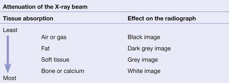
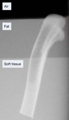
The tissues that lie in the path of the X-ray beam absorb (ie attenuate) X-rays to differing degrees. These differences account for the radiographic image.
 |
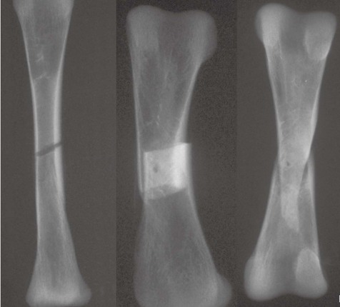
Fracture lines: usually black, but sometimes white
When a fracture results in separation of bone fragments, the X-ray beam that passes through the gap is not absorbed by bone. This results in a black (ie lucent) line on the radiograph.
On the other hand, bone fragments may overlap or impact into each other. The resultant increased thickness of bone absorbs more of the X-ray beam and so results in a white (ie sclerotic or denser) area on the radiograph.
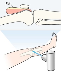
Fat pads and fluid levels
There are radiological soft tissue signs which can provide a clue that a fracture is likely. These include displacement of the elbow fat pads (see pp. 97 and 102), or the presence of a fat–fluid level at the knee joint (see pp. 248–249).
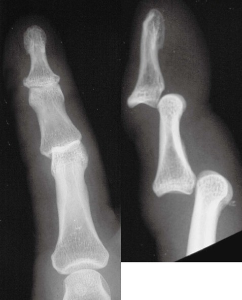
The principle of two views
‘One view only is one view too few’
Many fractures and dislocations are not detectable on a single view. Consequently, it is normal practice to obtain two standard projections, usually at right angles to each other. The example below shows two views of an injured finger.
At sites where fractures are known to be exceptionally difficult to detect (for example a suspected scaphoid fracture), it is routine practice to obtain more than two views.
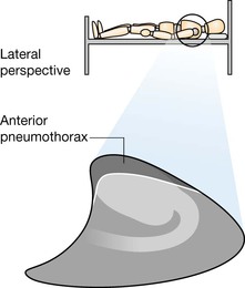
Important information: patient position
Knowledge of the patient’s position during radiography is essential. A radiograph obtained with the patient lying supine may produce a very different appearance when compared with the image acquired with the patient erect.
Assessing the radiographs: discipline is essential
Missed injuries are common following trauma6–9. Detection of a fracture, and the components of a complex injury, depends on adherence to three cardinal rules:
▪ Rule 1. Always analyse both views.
▪ Rule 3. Check whether radiographs from the past exist. A change in appearance will often assist you in recognising an important abnormality. Similarly, an unchanged appearance may stop you from erroneously diagnosing a new injury or fracture10.
Describing injuries
Fractures of the long bones
The radiographic appearance of a fracture needs to be described in a consistent style using accepted terminology. Imagine that you are describing a fracture of a long bone to the surgeon over the telephone11–13. These are the features the surgeon will want you to describe—simply and accurately:
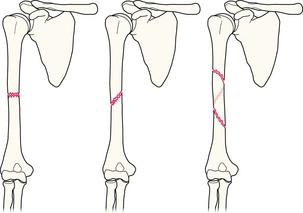
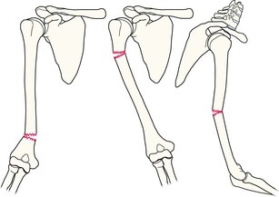
Articular surface involvement.
If a joint surface is involved the fracture is intra-articular.
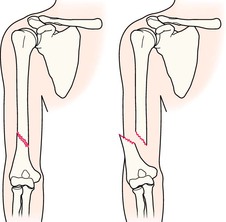
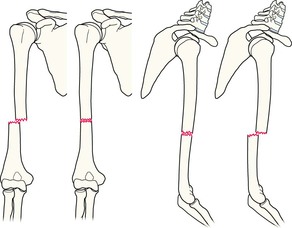
Position of the two major fragments.
Displaced or undisplaced.
Displacement is always described in relation to the distal fragment.
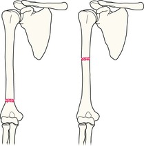
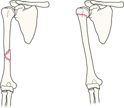
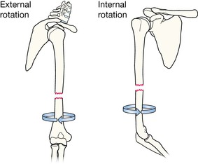
Rotational deformity.
A fragment has rotated on its long axis. Rotation may be external (left) or internal (right). Spontaneous correction is rare and surgery is usually required.
NB: Rotation of a fragment on its long axis is diagnosed most reliably by clinical examination. However, fragment rotation may be evident on the radiographs.
Dislocations
Precise use of language is important when describing subluxations and dislocations.
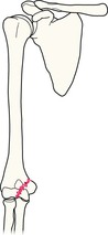
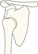
Subluxation
The joint surfaces are no longer congruous but the articular surface of one bone maintains some contact with the articular surface of the adjacent bone.
Example: inferior subluxation of the humeral head.
Dislocation
The articular surfaces at the joint have lost all contact with each other.
Example: inferior dislocation of the humeral head.
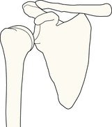
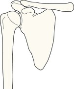
Normal joint
For reference.
[/level-membership-for-radiology-category][not-level-membership-for-radiology-category]
Key principles
Basic radiology
The radiographic image
The tissues that lie in the path of the X-ray beam absorb (ie attenuate) X-rays to differing degrees. These differences account for the radiographic image.
|
|
Fracture lines: usually black, but sometimes white
When a fracture results in separation of bone fragments, the X-ray beam that passes through the gap is not absorbed by bone. This results in a black (ie lucent) line on the radiograph.
On the other hand, bone fragments may overlap or impact into each other. The resultant increased thickness of bone absorbs more of the X-ray beam and so results in a white (ie sclerotic or denser) area on the radiograph.
Fat pads and fluid levels
There are radiological soft tissue signs which can provide a clue that a fracture is likely. These include displacement of the elbow fat pads (see pp. 97 and 102), or the presence of a fat–fluid level at the knee joint (see pp. 248–249).
The principle of two views
‘One view only is one view too few’
Many fractures and dislocations are not detectable on a single view. Consequently, it is normal practice to obtain two standard projections, usually at right angles to each other. The example below shows two views of an injured finger.
At sites where fractures are known to be exceptionally difficult to detect (for example a suspected scaphoid fracture), it is routine practice to obtain more than two views.
Important information: patient position
Knowledge of the patient’s position during radiography is essential. A radiograph obtained with the patient lying supine may produce a very different appearance when compared with the image acquired with the patient erect.
[/not-level-membership-for-radiology-category]
