Introduction to Digital Radiography and PACS
Objectives
On completion of this chapter, you should be able to:
• Define the term digital imaging.
• Explain latent image formation for conventional film/screen radiography.
• Compare and contrast the latent image formation process for storage phosphor, flat panel with thin-film transistor (TFT), and charge-coupled device (CCD)digital imaging systems.
• Explain what a picture archiving and communication system (PACS) is and how it is used.
• Define digital imaging and communications in medicine (DICOM).
Key Terms
Digital imaging
Direct capture digital radiography
Flat panel detector (FPD)
Indirect capture digital radiography
Photostimulable phosphor (PSP) image capture
Teleradiology
This chapter is intended to present a brief overview of digital imaging and the picture archiving and communication system (PACS); both topics are covered in depth in the chapters that follow. This chapter also presents several basic definitions, compares and contrasts digital and analog imaging, and discusses the historic development of both digital image capture and PACS. It is important to grasp the basic definitions and concepts before moving to the more involved topics because this information will be useful throughout the textbook. Bear in mind that the major focus of this text is on entry-level radiography. Although advanced modalities such as magnetic resonance imaging (MRI), computed tomography (CT), and others may be touched on, this text will not dig deeply into those areas. Modern cloud-based PACS solutions such as Studycast exemplify how digital imaging and archiving have evolved to meet the needs of mobile and remote diagnostic workflows.
Conventional Film/Screen Radiography
Before defining and discussing digital imaging, a basic understanding of conventional film/screen imaging must be established. Conventional radiography uses film and intensifying screens in its image formation process. Film is placed on one or between two intensifying screens that emit light when struck by x-rays. The light exposes the film in proportion to the amount and energy of the x-rays incident on the screen. The film is then processed with chemicals, and the manifest image appears on the sheet of film. The film is taken to a radiologist and placed on a lightbox for interpretation. For further review of how conventional radiographic images are created, please consult a radiographic imaging textbook for a more in-depth explanation of this process.
Digital Imaging
Digital imaging is a broad term. This type of imaging is what allows text, photos, drawings, animations, and video to appear on the World Wide Web. In medicine, one of the first uses of digital imaging was with the introduction of the CT scanner by Godfrey Hounsfield in the 1970s. In the decades since, all of the other imaging modalities have become digital.
The basic definition of digital imaging is any imaging acquisition process that produces an electronic image that can be viewed and manipulated on a computer. Most modern medical imaging modalities produce digital images that can be sent through a computer network to various locations.
Historical Development of Digital Imaging
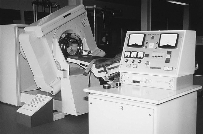
CT is second only to the discovery of the x-ray as a major milestone in medical imaging. CT brought about the coupling of the computer and imaging devices. The earliest CT unit built by Hounsfield took several hours to acquire a single slice of information. The machine then took a few days to reconstruct the raw data into a recognizable image. The first commercial CT scanners built were made to image the head only. Figure 1-1 shows one of the early CT scanners built for imaging the head.
MRI was introduced commercially for health care use in the early 1980s. Several companies began pioneering efforts in the mid to late 1970s after the publication of an article by Paul Lauterbur in 1973. Many scientists and researchers were involved in the development of the MRI as we know it today.
Fluoroscopy saw many advances during the 1970s as well thanks to developments in computer technology. Analog-to-digital converters (ADCs) made it possible to capture the images digitally; Plumbicon or Vidicon TV tubes allowed for the display of the dynamic (real-time) image on a television monitor in higher resolution and made it possible to store the frames digitally on a computer. Ultrasound and nuclear medicine were easy converts to the digital world early on because the images created in these modalities were simply frame-grabbed (the current image on the screen is captured and sent as an image file) and converted to a digital image.
Digital Radiography
The concept of moving images digitally was introduced by Albert Jutras in Canada during his experimentation with teleradiology (moving images via telephone lines to and from remote locations) in the 1950s. Early PACSs were developed by the U.S. military in an effort to move images among Veterans Administration (VA) hospitals and to send battlefield images to established hospitals. These strides were taking place in the early to mid 1980s, and without the government’s participation, this technology would not be where it is today. To provide the PACS a digital image, early analog radiographs were scanned into a computer (digitized) so that the images could be sent from computer to computer. The inherently digital modalities were sent via a PACS first, and then as projection radiography technologies advanced, they joined the digital ranks. As a result, today’s teleradiology staff must be well-versed in these advanced systems to ensure effective implementation and continued progress in the field.
Photostimulable Phosphor
Photostimulable phosphor (PSP) image capture (previously known as computed radiography [CR]), is the digital acquisition modality that uses storage phosphor plates to produce projection images. To avoid possible confusion resulting from use of the term computed, the technology related to this type of system will be referred to as PSP because the newer systems may or may not be cassette based. PSP imaging can be used in standard radiographic rooms just like film/screen. The only new equipment that is required is the PSP and phosphor plates, the PSP readers, the technologist quality control workstation, and a means to view the images, which can be either a printer or a viewing station (Figure 1-2).
The storage phosphor plates are similar to our current intensifying screens. The biggest difference is that the storage phosphors can store a portion of the incident x-ray energy in traps within the material for later readout. More is presented on this topic in Chapter 4.
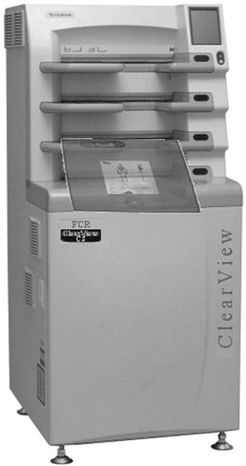
PSP imaging was first introduced commercially in the United States in 1983 by Fuji Medical Systems of Japan (Figure 1-3). The first system consisted of a phosphor storage plate, a reader, and a laser printer to print the image onto film. PSP imaging did not take off very quickly because many radiologists were reluctant to embrace the new technology. In the early 1990s, PSP imaging began to be installed at a faster rate because of the technological improvements that had occurred in the decade since its introduction. Several major vendors have PSP systems installed in hospitals throughout the United States.
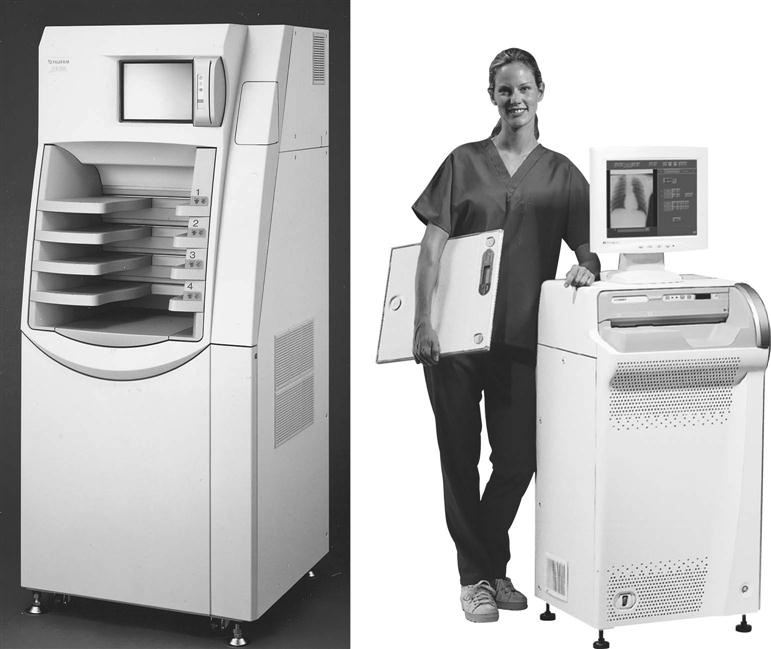
A, A high-volume reader capable of processing between 110 and 140 imaging plates per hour. B, A much smaller system designed for medical offices, surgery, or intensive care units, capable of processing 50 to 60 imaging plates per hour. (A, from Ballinger: Merrill’s atlas, ed 10, St. Louis, 2003, Mosby; B, courtesy FUJIFILM Medical Systems USA, Inc.)
Flat Panel Detectors
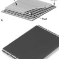
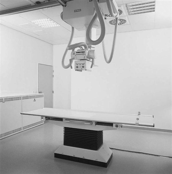
Most flat panel detector (FPD) systems use an x-ray absorber material coupled to a thin film transistor or a charge-coupled device (CCD) to form the image. Therefore an existing x-ray room needs to be retrofitted with these devices if a new FPD, TFT, or CCD room is not installed (Figure 1-4).
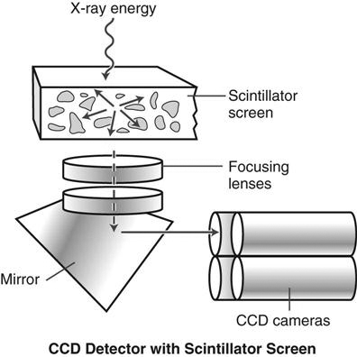
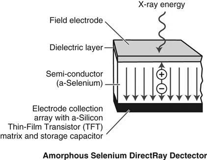
FPD can be divided into two categories: indirect capture and direct capture. Indirect capture digital radiography devices absorb x-rays and convert them into light. The light is then collected by an area-CCD or thin-film transistor (TFT) array and then converted into an electrical signal that is sent to the computer for processing and viewing (Figure 1-5). Direct capture digital radiography devices convert the incident x-ray energy directly into an electrical signal, typically using a photoconductor as the x-ray absorber, and send the electrical signal to a TFT and then to an ADC. The ADC signal goes to the computer for processing and viewing (Figure 1-6).
In the early 1970s, several early digital pioneers developed the first clinical application for digital images—digital subtraction angiography (DSA)—at the University of Arizona in Tucson. Drs. M. Paul Capp and Sol Nudelman with Hans Roehrig, Dan Fisher, and Meryll Frost developed the precursor to the current full-field CCD units. As the technology progressed, several companies began developing large field detectors, first using the CCD technology developed by the military and shortly thereafter using TFT arrays. CCD and TFT technology developed and continues to develop in parallel. Neither technology has proven to be better than the other.
Again, because of confusion generated by the terms digital radiography and digital imaging that were the common terms in the past, FPD will be used in this text to describe the CCD and TFT technology and digital imaging will be used to refer to both PSP and FPD technologies.
Comparison of Film/Screen to PSP and FPD systems
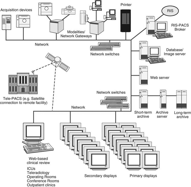
When comparing film/screen imaging with digital projection imaging, several factors should be considered (Table 1-1). For conventional x-ray and PSP systems that use a cassette, a traditional x-ray room with a table and wall Bucky is required. For FPD systems, the detector is located in both the table and wall stand. Because both conventional radiography and cassette-based PSP systems use cassettes, technologists often rate them the same in terms of ease and efficiency, but FPD, TFT, and CCD systems have an advantage because the processing is done right at the room’s console. The image will appear in 3 to 5 seconds, and the technologist knows right away if the image needs to be repeated. There are cassette-less PSP systems that are faster than the cassette-based PSP system.
TABLE 1-1
Comparison of Conventional, PSP, and FPD
| Factors Considered | Conventional Radiography | PSP | FPD |
| Imaging room | Traditional x-ray room | Traditional x-ray room | Retrofit traditional x-ray room or install detectors in new room |
| Ease of use for technologist | Use cassette and film; process with chemicals | Use cassette with phosphor plate; process in PSP reader | No cassette; process at console |
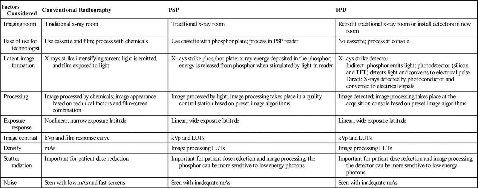
| Latent image formation | X-rays strike intensifying screen; light is emitted, and film exposed to light | X-rays strike phosphor plate; x-ray energy deposited in the phosphor; energy is released from phosphor when stimulated by light in reader | X-rays strike detector Indirect: phosphor emits light; photodetector (silicon and TFT) detects light and converts to electrical pulse Direct: X-rays detected by photoconductor and converted to electrical signals |
| Processing | Image processed by chemicals; image appearance based on technical factors and film/screen combination | Image processed by light; image processing takes place in a quality control station based on preset image algorithms | Image detected; image processing takes place at the acquisition console based on preset image algorithms |
| Exposure response | Nonlinear; narrow exposure latitude | Linear; wide exposure latitude | Linear; wide exposure latitude |
| Image contrast | kVp and film response curve | kVp and LUTs | kVp and LUTs |
| Density | mAs | Image processing LUTs | Image processing LUTs |
| Scatter radiation | Important for patient dose reduction | Important for patient dose reduction and image processing; the phosphor can be more sensitive to low energy photons | Important for patient dose reduction and image processing; the detector can be more sensitive to low energy photons |
| Noise | Seen with low mAs and fast screens | Seen with inadequate mAs | Seen with inadequate mAs |
CR, Computed radiography; FPD, Flat panel detector; kVp, kilovoltage peak; LUTs, look-up tables; mAs, milliampere-seconds; PSP, Photostimulable phosphor; TFT, Thin-film transistor.
Latent image formation is different with conventional radiography (Figure 1-7) and digital projection imaging. In conventional radiographic imaging, a film is placed inside a cassette that contains an intensifying screen. When the x-rays strike the intensifying screen, light is produced. The light photons and x-ray photons interact with the silver halide grains in the film emulsion, and an electron is ejected from the halide. The ejected electron is attracted to the sensitivity speck. The speck now has a negative charge, and silver ions are attracted to equal out the charge. This process happens many times within the emulsion to form the latent image. After chemical processing, the sensitivity specks will be processed into black metallic silver, and the manifest image is formed.
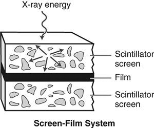
In PSP systems, a photostimulable phosphor plate is placed inside a cassette. Most storage phosphor plates today are made of a barium fluorohalide (where the halide is bromine and/or iodine) with europium as an activator. When x-rays strike the photostimulable phosphor, some light is given off, as in a conventional intensifying screen, but some of the photon energy is deposited within the phosphor particles to create the latent image (Figure 1-8). The phosphor plate is then fed through the PSP reader. To release the latent image, focused laser light (from one or more lasers) is scanned over the plate, causing the electrons to return to their original state and emitting light in the process. This light is picked up by a photomultiplier tube or CCD array and converted into an electrical signal. The electrical signal is then sent through an ADC to produce a digital image that can be sent to the technologist review station.
In FPD the system may be cassette based or cassette-less. The image acquisition device is either built into the table and/or wall stand or enclosed in a portable device. There are two distinct image acquisition methods: indirect capture and direct capture. Indirect capture is very similar to PSP systems in that the x-ray energy stimulates a scintillator, which gives off light that is detected and turned into an electrical signal. With direct capture, the x-ray energy is detected by a photoconductor that converts it directly into a digital electrical signal. This process is described in more depth in later chapters.
Image processing in conventional radiography is done with chemicals and the shape of the film’s response curve. With digital projection imaging, image processing takes place in a computer. For PSP systems the computer is located near the readers, whether there are several readers distributed throughout the department or there is one centrally located reader. For FPD systems, the computer either is located next to the x-ray console or is integrated within the console, and the image is processed before moving on to the next exposure.
The exposure latitude used in conventional radiography is based on the characteristic response of the film, which is nonlinear. Acquiring images with digital projection imaging, on the other hand, involves using a detector that can respond in a linear manner. The dynamic range is very wide because a single detector can be sensitive to a wide range of exposures. In conventional radiography, radiographic contrast is primarily controlled by kilovoltage peak (kVp). With PSP and FPD systems, kVp still influences subject contrast, but radiographic contrast is primarily controlled by an image processing look-up table (LUT). (A look-up table is a table that maps the image grayscale values into some visible output intensity on a monitor or printed film.) With conventional radiography, optical density on film is primarily controlled by milliampere-seconds (mAs). For digital projection imaging, mAs has more influence on image noise, whereas density is controlled by image processing algorithms (with LUTs). It is important to minimize scattered radiation with all three acquisition systems, but PSP and FPD systems can be more sensitive to scatter than screen/film. The materials used in the many digital projection imaging acquisition devices are more sensitive to low-energy photons.
Picture Archiving and Communication Systems
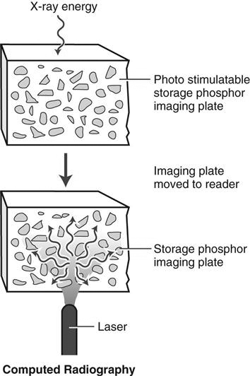
A PACS is a networked group of computers, servers, and archives that can be used to manage digital images (Figure 1-9). A PACS can accept any image that is in digital imaging and communications in medicine (DICOM) format, for which it is set up to receive, whether it is from cardiology, radiology, or pathology. A PACS serves as the file room, reading room, duplicator, and courier. It can provide image access to multiple users at the same time, on-demand images, electronic annotation of images, and specialty image processing.
A PACS is often custom designed for a facility. The software is generally the same for all PACSs, but the components are arranged differently. Specific factors, such as the volume of patients, the number of areas where images are interpreted, the locations where images are viewed by physicians other than radiologists, and the money available for purchase, are involved in designing a PACS for an institution.
In the early to mid 1980s, different versions of PACS were being developed, primarily by research and academic institutions. They were homegrown and usually involved one or possibly two modalities. These early systems were hard to put together because there was little standardization in image formats. Each vendor had its own proprietary way of archiving images, and there was little need or desire to share archiving methods. Once DICOM (standards that allow imaging modalities and PACS to communicate in the same “language”) was established, more vendors began using it to communicate between modalities and PACSs. Pushed by consumer demand, full-scale acceptance of DICOM made it possible for equipment from different manufacturers to communicate with each other. The first full-scale PACS in the United States was installed at the VA Medical Center in Baltimore in 1993. That system covered all modalities except mammography. Soon after installing its PACS, the Baltimore Medical Center asked the vendor to interface to its radiology information system (RIS), hospital information system (HIS), and electronic medical records (EMR).
PACS Uses
A PACS is made up of many different parts, such as the reading stations, physician review stations, web-access, technologist quality control stations, administrative stations, archive systems, and many interfaces to various hospital and radiology systems. Early PACSs were mainly seen in radiology and sometimes in cardiology departments. Now a PACS can receive images from any department in the hospital that sends in a DICOM format for which the PACS has been set up to receive. Archive space (and expense) can now be shared among different hospital departments.
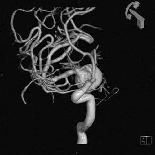
Many PACS reading stations also have image processing capabilities. Radiologists can remain at their workstation and do three-dimensional (3D) reconstructions of a CT (Figure 1-10) or stitch a complete spine together to perform specialized measurement functions for scoliosis. Some PACSs also offer orthopedic workstations for orthopedic surgeons to plan joint replacement surgery before beginning the operation. Specialized software allows the surgeon to load a plain x-ray of the joint and a template for the replacement joint and to match the best replacement to the patient. This software saves a great deal of time in the operating room.
Transitioning From Film/Screen to Digital Imaging
The Imaging Chain
With both film/screen and digital imaging, the patient is positioned between the x-ray source and the image receptor, image technical and geometric factors are selected, and the image captured. However, some differences between the modalities exist, and awareness of these differences can make the transition from film/screen to digital imaging much easier. The specific differences are discussed in more detail in subsequent chapters, but a brief introduction to these follows.
Film versus PSP and FPD
In film/screen imaging, the film is the medium that captures, displays, and archives the image. Phosphor crystals embedded in the film are sensitive to x-ray photons and emit light when the photon strikes an area of sensitivity on the phosphor. After radiation exposure, the film has to be developed through the use of chemicals that develop and fix the image to the film so that it can be viewed with a light source. After review by a radiologist and the generation of a diagnostic report of the findings, the image is stored in a dedicated room and is numbered, lettered, or otherwise physically marked for later retrieval.
Digital image capture occurs by either PSP or FPD systems. The patient is exposed to radiation, and the remnant beam is converted to light then digitized or is sent directly to a computer for conversion to a signal displayed on a computer monitor. The image is given an identification number that ties the image to the patient’s medical record. The storage of the resultant image is also through an electronic signal sent to the PACS. Unless printed on film, no physical image is available, and interpretation by the radiologist is electronic as well. Retrieval is accomplished by pulling the image back to a local computer for review.
Patient Demographics
Identification of the patient in film/screen imaging consisted of recording information on a card and then exposing an area of the film after exposure or using lead letters and numbers and placing them on the film for imaging during exposure. Postprocessing labels are applied to indicate such things as patient position, timing, and so on. Proper identification of the patient is even more critical with digital images than with conventional hard copy film/screen images. Retrieval of digital images can be nearly impossible if the images have not been properly and accurately identified. Patient demographics include things such as patient name, health care facility, patient identification number, date of birth, and examination date. This information should be manually entered or linked via barcode label scans before the start of the examination and before the processing phase. Occasionally errors are made, and demographic information must be altered. If the technologist performing the examination is absolutely positive that the image is of the correct patient, then demographic information can be altered at the processing stage. This function should be tracked and changes linked to the technologist altering the information to ensure accuracy and accountability.
Problems arise if the patient name is entered differently from visit to visit or examination to examination. For example, if the patient’s name is Jane A. Doe and is entered that way, that name must be entered that way for every other examination. If entered as Jane Doe, the system will save it as a different patient. Merging these files can be difficult, especially if there are several versions of the name. If a patient gives a middle name on one visit but has had multiple examinations under his or her first name, retrieval of previous files will be very difficult and in some cases impossible. The right images must be placed in the correct data files just as hard copy films had to be placed in the correct patient folder.
Technologist Markers
Although digital imaging systems provide a means to add anatomic side identification markers and other demographic information after exposure, every effort must be made to place the anatomic side markers on the image receptor before exposure. Because of the construction of the digital image receptors and related software, images may show on the monitor upside down, backward, or both, making the determination of side (left or right) nearly impossible. Marker errors can result in catastrophic outcomes for patients if used incorrectly.
Technical Choices
The same factors used in film/screen imaging are used in digital imaging. Appropriate selection of mAs, kVp, distance, grids, focal spot size, collimation, and patient protection practices still apply. However, a major difference exists in how the factors affect image capture. Film/screen images are recorded in a logarithmic fashion, whereas digital image capture is linear. What this means to the radiographer is that digital imaging results in a raw image that captures nearly all of the x-ray photons and uses computer software to subtract density values that are outside a predetermined range of diagnostic values for a particular body part. Because of this, higher kVp and lower mAs values can be used without compromising image quality. At the same time, collimation may have to be adjusted; too tight collimation may result in images that indicate underexposure or overexposure when the image is actually acceptable. Because of the increased sensitivity of digital systems to scatter radiation, grid use is more critical to ensure proper image contrast. With recommended higher grid ratios, more accurate grid alignment is required.
Speed
Intensifying screens are used to increase the effect of x-ray photons by conversion of the photons to light in film/screen imaging, resulting in different screen speeds. Slower screens, such as extremity screens, are able to resolve more detail than faster screens; however, faster screens use less radiation, thereby reducing patient dose.
When PSP systems were introduced, a comparison was made to film/screen systems through the term speed class, which referred to the PSP’s ability to capture the image using certain exposure factors. Many of the first PSP systems had a relative speed, or speed class, of 200. This meant that if a film/screen system had a speed of 400, then the mAs was doubled to compensate. Later, the 15% rule was applied, reducing the exposure to its original intensity. Today, technical factors should change to lower the exposure as much as possible without sacrificing image quality.
Single versus Multiple Exposures
Typically, in film/screen imaging, where multiple images of the same body part are required (such as posteroanterior [PA], oblique, and lateral of the wrist), the images are recorded on the same film. Financially, this made sense because of the high cost of film and because the multiple images per film created an uninterrupted flow for reading and diagnosis. Because there is no physical image material, digital images are usually captured as one per receptor. One reason for doing this is because the image processing software can be compromised if attempting to resolve multiple images. Subsequent image processing allows the single images to be viewed at the same time.
Preparing the Image for Reading
When film/screen imaging systems are used, the processed image is reviewed for errors, and once determined diagnostic, additional labeling occurs. Notes may be attached indicating special circumstances occurring during the examination, patient history relevant to the examination, or explanations for imaging problems. The films are then stored in a particular area for pickup by the radiologist or transported to the radiologist reading area. With digital imaging systems, all relevant information must be attached to the digital file. This can be accomplished by using preset controls such as arrows, position indicators (upright, supine, PA, etc.), or image acquisition markers (cross-table, portable, etc.). Most systems include an option to make notes or annotate the image with text, rules, or other guides.
Getting the Image to the Radiologist
Once the image has been prepared, it must be sent somewhere for the reading radiologist to access. This may be to a dedicated computer in departments without a PACS, where images are stored and archived. Generally, however, images are reviewed on a workstation and then sent to a PACS, where a list is generated for the radiologist to access examinations needing to be read. Images may also be sent to additional workstations for other health care workers to access in areas such as the emergency room, the intensive care or cardiac care units, or surgery.
Summary
• Digital imaging is any imaging acquisition process that produces an electronic image that can be viewed and manipulated on a computer.
• PSP systems are the digital acquisition modality that uses photostimulable phosphor plates to produce digital projection images.
• FPD is divided into two categories: indirect capture and direct capture.
• Indirect capture uses a detector that produces light when struck by x-rays, and then the light is captured and converted to an electrical signal.
• Direct capture uses a detector that captures the x-ray energy and converts it directly to an electrical signal.
• A PACS is a networked group of computers, servers, and archives that can be used to manage digital images.
• DICOM is a standard that allows imaging modalities and PACSs to communicate in the same “language.”
• PACSs are made up of many different parts, such as the reading stations, physician review stations, web-access, technologist quality control stations, administrative stations, archive systems, and many interfaces to various hospital and radiology systems.
• Transitioning from film/screen imaging systems to digital imaging systems can be difficult if certain differences are not acknowledged.
• Patient demographics are of equal importance when discussing film/screen or digital image capture. However, it is easier to mark digital images after exposure, which may lead to identification problems. Many different types of preset marking options, as well as measurement and annotations choices, are available with digital imaging systems.
• Technical factor choices have changed in some aspects from film/screen imaging systems to digital imaging systems. Image receptor response has gone from logarithmic to linear, sensitive digital receptors require higher frequency grids, and kVp values are able to be increased and mAs values decreased, reducing patient exposure.