[level-membership-for-cardiovascular-category]
7 Intravascular Ultrasound
Principles and Clinical Applications
Technical Background
Gray-Scale Intravascular Ultrasound
Gray-scale intravascular ultrasound (IVUS) utilizes one or more miniaturized transducers secured at the end of a flexible catheter that is inserted into arteries for in vivo tomographic visualization of vascular anatomy. Intracoronary ultrasound has become the most commonly used form of intravascular imaging and is regularly employed to delineate plaque morphology and distribution, to assess angiographically ambiguous lesions, to assess atherosclerosis progression and regression, to guide transcatheter coronary intervention, and to assess mechanisms of restenosis (Fig. 7-1).1–2 The IVUS catheter is attached to either a portable or installed ultrasound machine through an interface that ensures sterility of the catheter and allows for motorized pullback. Motorized pullback of the IVUS catheter (or of the transducer within the catheter) at 0.5 mm/s or 1.0 mm/s allows calculation of lesion length and plaque volumes (necessary for progression/regression studies), ensures adequate time to visualize the lesion, and allows comparison between IVUS “runs” done at different times but with similar pullback speeds.
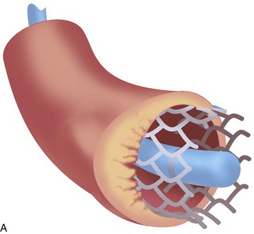
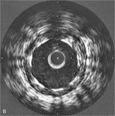
Image Formation
An IVUS image is formed when ultrasound bounces off the multiple layers of the artery and returns to the transducer.3 The coronary artery is a muscular vessel composed of three basic layers: intima, media, and adventitia (Fig. 7-2). The intima, only a few cells thick at birth, is the site of atherosclerotic plaque accumulation. The intima is directly surrounded by the media, a layer of predominately homogeneous smooth muscle cells that provides the artery with its vascular tone. The outermost layer is the adventitia. Each of these layers tends to have a different acoustic property, allowing each to be visualized separately. When ultrasound encounters the intima, there is a large change in acoustic impedance; and much of it is bounced back to the transducer and displayed as a single concentric echo. Unless the intima becomes extremely hard, such as with the formation of a calcified plaque, some ultrasound penetrates through to the media. Because the media is composed of homogeneous smooth muscle cells, it passes through with minimal reflection; thus the media appears as a dark zone devoid of echoes. The adventitia has numerous layers of collagen fibers and therefore is a highly reflective structure that appears bright. As a result of the different acoustic properties of each layer, the normal coronary artery has a three-layered appearance, which includes (1) a bright echo from the intima, (2) a dark zone from the media, and (3) bright echoes from the adventitia. Because the resolution of IVUS is approximately 100 to 120 µm, the intima has to be at least this thick to be visualized as a distinct structure. In Western society, most patients presenting to the cardiac catheterization laboratory have some diffuse thickening of the intima. But if the intima is truly disease free, as in a newborn, child, or adolescent, then the intima will be much thinner and below the resolution of IVUS so that the artery will appear as a monolayer (see Fig. 7-2).
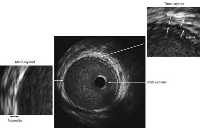
Image Interpretation
The interpretation of an IVUS image involves only a few simple steps: (1) identify the IVUS catheter in the center of the screen, keeping in mind that the IVUS catheter is traveling down the blood-filled lumen; (2) identify the dark stripe of the media that tells the size of the artery in the absence atherosclerotic disease; (3) remember that all of the echoes within the media stripe represent intima or intimal (atherosclerotic) disease and (4) all of the echoes outside the media are adventitia (see Fig. 7-2).
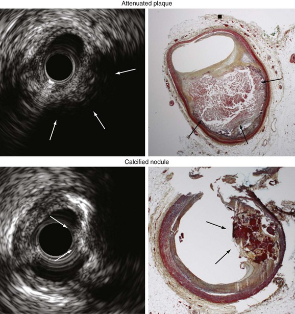
The amount of ultrasound that reflects off of tissue depends on the acoustic impedance (density) of the tissue. This property provides IVUS with some ability to differentiate plaque of different compositions. Hard material (calcium or fibrotic plaque) will reflect more ultrasound and appear brighter, whereas soft plaque (fat) will not reflect the ultrasound and will appear dark. Calcium is so dense that no ultrasound penetrates to the deeper tissues and, thus, produces acoustic shadows; shadowing, along with the bright echoes is the hallmark of calcification. A conventional approach is to compare the overall brightness of the plaque to the surrounding adventitia. Plaque is typically characterized as hypoechoic if less dense than the adventitia, hyperechoic if more dense than the adventitia, calcified if bright with acoustic shadowing, or mixed. IVUS can detect dense calcium with high sensitivity and specificity,4–6 but its accuracy in identifying high-risk lipid rich plaque or even thrombus formation is poor.7 As shown in Figure 7-3, gray-scale IVUS can also detect two other types of high-risk plaques: (1) noncalcified attenuated plaque (which correlates with fibroatheroma) and (2) calcium nodules (calcium with a convex shape and irregular surface).8–10
Radiofrequency Ivus
Standard gray-scale IVUS is limited, in part, because it uses only the amplitude of reflected ultrasound to formulate the image. In an effort to improve on the qualitative assessment of the reflected ultrasound signal, Kawasaki and coworkers developed a plaque characterization algorithm called integrated backscatter IVUS using time domain information directly from the radiofrequency signal. This process has resulted in improved plaque characterization with a reported in vitro sensitivity of 90% and specificity or 92% for lipid-rich plaque.11
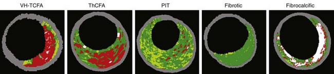
In a similar effort to improve plaque characterization, spectral analysis (virtual histology [VH]-IVUS) combines signal frequency and amplitude analysis to create an algorithm that detects fibrous tissue (dark green), fibrofatty (light green), necrotic core (red), and dense calcium (white). Reported sensitivity and specificity of VH-IVUS are 91.7% and 96.6% for identification of the lipid-rich necrotic core.12–14 However, VH-IVUS cannot detect thrombus (in fact, thrombus appears as either fibrotic or fibrofatty plaque depending on the age of the thrombus) and has not been validated for assessment of stent metal or intimal hyperplasia. VH-IVUS lesion phenotype has been classified as (1) VH thin-cap fibroatheroma, (2) thick-cap fibroatheroma, (3) pathologic intimal thickening, (4) fibrotic plaque, and (5) fibrocalcific plaque (Fig. 7-4). Fibrotic plaque has mainly fibrous tissue with less than 10% confluent necrotic core, less than 10% confluent dense calcium, less than 15% fibrofatty. Fibrocalcific plaque has mainly fibrous tissue with greater than 10% confluent dense calcium, but less than 10% confluent necrotic core. Pathologic intimal thickening has a mixture of all plaque components, but dominantly fibrofatty with less than 10% confluent necrotic core and less than 10% confluent dense calcium. Fibroatheroma (both VH thin-cap fibroatheroma and thick-cap fibroatheroma) has greater than 10% confluent necrotic core. Because the resolution of VH-IVUS is 150 to 250 µm, it is not possible to detect fibrous cap thickness less than 65 µm (the typical pathologic definition of a thin fibrous cap). Therefore, if there is greater than 30° of necrotic core abutting to the lumen in three consecutive slices, the fibroatheroma is classified as VH thin-cap fibroatheroma; otherwise, it is classified as thick-cap fibroatheroma.15
Ivus Versus Angiography
It has been verified in autopsy studies and other IVUS studies of healthy donors that most people have diffuse atherosclerotic disease throughout their arteries by midlife, and this disease often remains angiographically silent because of its diffuse nature. In addition to diffuse plaque, vascular remodeling is also responsible for the high prevalence of angiographically silent disease. Both pathology and IVUS studies have documented that coronary arteries will enlarge to accommodate focal plaque deposition in an attempt to maintain luminal integrity. Compensatory dilation of the arterial wall occurs in direct response to the accumulation of atherosclerotic plaque. An absolute reduction in lumen dimensions typically does not occur until the lesion occupies approximately 40% to 50% of the area within the internal elastic membrane (40% to 50% cross-sectional narrowing).16 As a result, most of the atherosclerotic burden is contained within angiographically normal reference segments.17
Clinical Applications
Safety
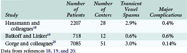
Three large studies have evaluated the safety of IVUS. Other than transient spasm, complications appear to be rare (Table 7-1).18–20
Assessment Of Stenosis Severity
Coronary angiography underestimates stenosis severity most markedly in vessels with 50% to 75% plaque burden (plaque area divided by arterial area) at necropsy and in patients with multivessel disease.21–25 Clinical events are determined by lumen size, not by the amount of plaque. Therefore, it is important to focus on accurate measurement of lumen dimensions and not to be distracted by the plaque burden. Plaque burden in patients with atherosclerosis tends to be large even in the absence of lumen compromise.
Studies performed more than 10 years ago suggested that an IVUS minimum lumen area (MLA) greater than 4 mm2 was a valid criterion for deferring an intervention based both on comparisons to physiologic measures and on follow-up data.26–29 This cutoff only applied to major epicardial vessels excluding the LMCA and excluding saphenous vein grafts. However, it was necessary to interrogate the lesion carefully to identify the image slice with the smallest lumen, especially in very focal stenoses. Once the smallest lumen is identified, careful measurement was required. Recently this cutoff has come under criticism for a number of reasons including the size of the vessels (studies were done mostly in large 3.5-mm vessels), the average MLA of the intermediate lesions studied (4 mm2), and the fact that these studies have been misinterpreted to suggest that lesions with an MLA below 4 mm2 justify stent implantation. For this reason, it is recommended that for major epicardial vessels excluding the LMCA, physiologic lesion assessment (using an intracoronary pressure wire and maximum hyperemia with intravenous adenosine to measure the fractional flow reserve) is a complementary approach to assess lesion severity.30
Assessment Of Lmca Disease
A high percentage of patients with angiographically “normal” LMCA with only nonsignificant stenosis have substantial disease by IVUS.31–34 Reasons for the discrepancy between angiography and necropsy or IVUS assessment of LMCA disease include the following: (1) diffuse atherosclerotic involvement affects the angiographic diameter stenosis (DS) calculation because of the lack of a normal reference segment; (2) a short LMCA also makes identification of a normal reference segment difficult; (3) unique geometric issues exist in LMCA disease (the correlation between angiography and necropsy or IVUS appears to be somewhat better in non-LMCA stenoses); and (4) there is significant interobserver and intraobserver variability in the angiographic assessment of LMCA disease.35–42 In fact, the LMCA is the coronary arterial segment with the greatest variability in angiographic assessment.
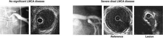
We reported 122 patients who underwent angiographic and IVUS assessment of the severity of LMCA disease, who did not have subsequent catheter or surgical intervention, and who were followed for 1 year.43 There were three distinct predictors of these cardiac events: diabetes; a major epicardial vessel or bypass graft with a quantitative angiography (QCA) DS greater than 50% that was left untreated; and LMCA lesion site minimal lumen diameter measured by IVUS. An example is shown in Figure 7-5.
Jasti and colleagues reported that an IVUS MLA of 5.9 mm2 or a minimal lumen diameter of 2.8 mm corresponded to physiologic ischemia (fractional flow reserve less than 0.75) in the LMCA.44 Hernandez and co-workers evaluated 354 angiographically intermediate (diameter of stenosis 25% to 60%) unprotected LMCA lesions by IVUS. Of the patients evaluated, 186 had an MLA of at least 6 mm2, and only 7 patients were revascularized.45 In 2 years, percentages for survival free of cardiac death (97.7%) and revascularization (96.5%) were very high, suggesting a MLA of 6 mm2 or greater as a safety cutoff to defer the revascularization of LMCA disease.
Lesion Length And Reference Dimensions
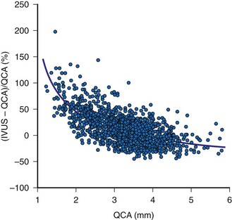
The two most important measurements for stent size selection are lesion length and reference dimension. Motorized transducer pullback is essential for length measurements and has been validated in vivo.46 A comparison of IVUS and QCA reference lumen measurements in 3311 nonostial native coronary arteries or saphenous vein graft lesions showed a QCA proximal reference lumen diameter of 3.05 ± 0.68 mm and an IVUS proximal reference lumen diameter of 3.41 ± 0.62 mm (p less than 0.0001 versus QCA). The difference between the IVUS and QCA measurements was 0.36 ± 0.64 mm or 15 ± 24%. This difference was greatest in the smallest vessels, decreased asymptotically with increasing vessel size, and was zero at a QCA reference of approximately 4 mm shown in Figure 7-6. This analysis suggests that, especially in the smaller arteries (which have higher restenosis rates), (1) the angiographic assessment of reference lumen dimensions is flawed and (2) an IVUS measurement would indicate that a larger device could be used that could result in larger final lumen dimensions without having to resort to midwall or media-to-media device/vessel sizing.47,48 Alternatively, some authorities have advocated the use of IVUS “true vessel,” “media-to-media,” or midwall dimensions for device sizing; however, this should only be done by highly experienced IVUS users because it carries a greater risk of acute complications such as stent edge dissection.
Unusual Lesion Morphology
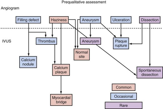
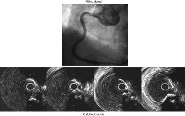
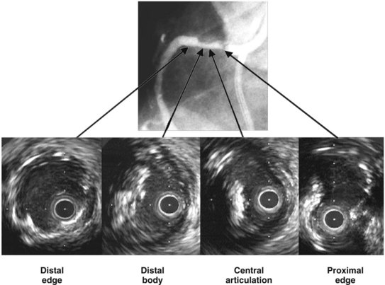
IVUS is useful in understanding lesions with an unusual angiographic appearance including filling defects, haziness, aneurysms, ulceration, myocardial bridge, and spontaneous dissection.49–53 Examples are summarized in Figure 7-7 and shown in Figures 7-8 through 7-11.
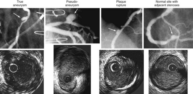
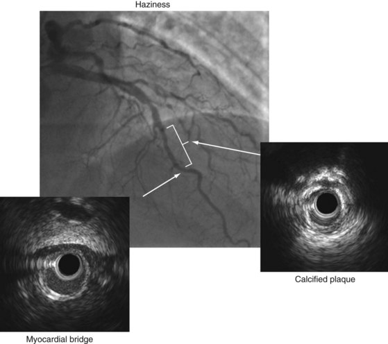
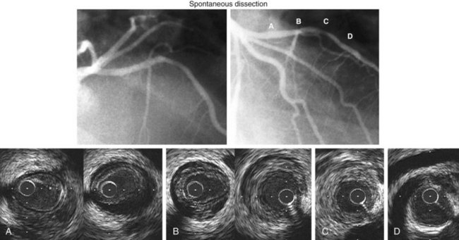
An IVUS classification of angiographic coronary artery aneurysms has also been created.50 Of 77 aneurysm-containing lesions, 21 (27%) were classified as true aneurysm; 3 (4%) were classified as pseudoaneurysms (all having previous intervention); 12 (16%) were complex plaques; and the other 41 (53%) were normal arterial segments adjacent to one or more stenoses. Examples are shown in Figure 7-9. In a study of 300 consecutive IVUS-defined plaque ruptures, 91% were categorized as complex by angiography: ulceration in 81%, intimal flap in 40%, thrombus in 7%, and coronary aneurysm in 7%.51 Approximately one quarter of patients had IVUS-detectable myocardial bridges in the LAD coronary artery; only 3% (11 of 331) were diagnosed by angiography. In 13% of cases, IVUS-detectable myocardial bridges appeared as mild (diameter of stenosis less than 25%) fixed lesions and/or angiographic haziness (see Fig. 7-10).52 Spontaneous dissections are an intramural process that appears as a medial dissection with an intramural hematoma occupying the dissected false lumen without intimal tears and without a communication between the true and false lumens.53 An example is shown in Figure 7-11.
Assessment Of Vulnerable Plaque
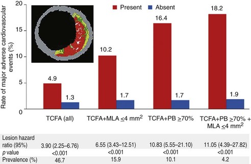
PROSPECT (Providing Regional Observations to Study Predictors of Events in the Coronary Tree) was a prospective study of the natural history of coronary atherosclerosis using angiography and VH-IVUS to identify the clinical and lesion-related factors that predicted future coronary events.15 It was performed at 37 sites in the United States and Europe. Patients with acute coronary syndromes were enrolled after undergoing successful percutaneous coronary intervention of all culprit lesions responsible for the acute event. Angiography was performed of the entire coronary tree followed by gray-scale and VH-IVUS of the proximal 6 to 8 cm of all epicardial arteries. All baseline angiograms and gray-scale and VH-IVUS images were prospectively analyzed without knowledge of subsequent events using prespecified definitions and methodology. Plaque burden and luminal area as prospectively measured by gray-scale IVUS and plaque composition (thin-cap fibroatheroma) as assessed by VH-IVUS were determined to be independent predictors of future adverse cardiovascular events (Fig. 7-12).
Prediction Of No-Reflow During Interventional Procedures
IVUS guidance may also be useful to identify high-risk lesions before intervention, such as those that cause no-reflow or periprocedural myocardial infarction, particularly noncalcified attenuated plaque.54–57 Noncalcified attenuated plaque may be a gray-scale indication of a larger necrotic core and/or fibroatheroma (96% of attenuated plaques contained a fibroatheroma vs. 52.3% on nonattenuated plaques, p <0.0001).9 In support of this, multiple VH-IVUS studies have shown that a larger necrotic core is related to distal embolization during percutaneous coronary intervention in both acute coronary syndromes and stable angina patients.58–61
Assessment Of Interventional Complications
IVUS detects poststent dissections or other complications more often than angiography.
One type of dissection, intramural hematoma, appears as an angiographic dissection in 60%, as newly developed stenosis that does not disappear after nitroglycerin (i.e., not a spasm) in 11%, and as no angiographic abnormality in 29%.62 Similarly, perivascular trauma appears as an angiographic perforation in 24%, as angiographic dissection in 33%, as new stenosis in 5%, and as no abnormality in 38%. Angiographic “haziness” at the stent edge may demonstrate an edge dissection or residual plaque, especially a calcified eccentric plaque, when studied by IVUS.
Restenosis, Late Malapposition, Stent Fracture, And Stent Thrombosis
In the bare metal stent (BMS) era, serial IVUS studies in humans showed (1) that tubular-slotted stent designs exhibit almost no chronic recoil, (2) that in-stent restenosis was almost entirely neointimal hyperplasia, (3) that there was no predilection for tissue accumulation within any one segment, and (4) that neointimal thickness was independent of stent size.63,64 It is for these reasons that many studies have reported that the absolute minimum stent area (MSA) by IVUS was the strongest quantitative predictor of clinical and angiographic in-stent restenosis.65–67
Because drug-eluting stents (DES) have less neointimal hyperplasia, the MSA necessary to minimize restenosis can be smaller than with BMS. Using the data from SIRIUS, Sonoda and coworkers reported that the best cutoff to predict an MLA at follow-up of 4 mm2 was an MSA of 5 mm2 for sirolimus-eluting stents (SES) and 6.5 mm2 for BMS.68 A similar study by Hong and colleagues showed that the MSA that best separated angiographic restenosis from no restenosis was 5.5 mm2 in SES.69 We combined various TAXUS studies and reported that the best cutoff to predict angiographic binary restenosis for the paclitaxel-eluting stent (PES) was 5.7 mm2.70 However, “bigger is better” is still true; also, (1) a larger MSA is still associated with a lower restenosis rate, whereas (2) an MSA of 5.0 to 5.5 mm2 may not be achievable in small vessels that are increasingly stented.
On the other hand, full lesion coverage may be more important in the DES era than in the BMS era. Costa and colleagues reported that longitudinal geographic miss (GM)—injured or diseased segment not covered by SES—was observed in 47.6%,; axial GM—balloon-artery size ratio less than 0.9 or greater than 1.3—was observed in 35.2%; and both GM in 16.5%.71 One-year target vessel revascularization rates were 6.1% in the longitudinal GM group versus 2.6% in the no-longitudinal GM group (p = 0.001); the GM was the independent predictor for target vessel revascularization. In support of this, Liu and co-workers reported that the stent edge plaque burden that best separated restenosis from no restenosis was approximately 50%.72
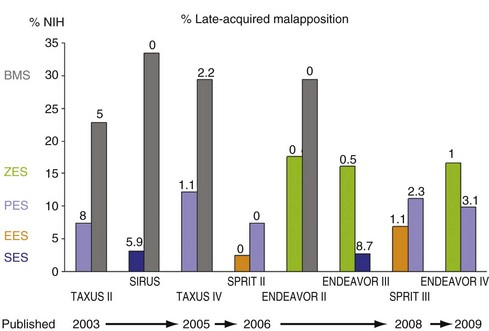
Figure 7-13 summarizes the percentage of neointimal hyperplasia (%NIH = NIH volume divided by stent volume) and late acquired malapposition in various multi-center randomized trials.73–83 In BMS, %NIH averaged (approximately) 30% of stent volume, and %NIH was consistently greater in diabetes than nondiabetes.84 In the DES era, %NIH was reported as 2.7% to 3.1% in SES, 2.5% to 6.9% in everolimus-eluting stents, 7.4% to 12.2% in PES, and 16.1% to 17.6% in zotarolimus-eluting stents. Though NIH varied among DES, the clinical efficacy (target vessel revascularization) and safety (stent thrombosis) were similar in noncomplex lesions.
IVUS predictors of either drug-eluting acute/subacute stent thrombosis or restenosis are stent underexpansion and residual edge “problems,” such as GM, adjacent secondary plaques, or significant edge dissections—but not acute malapposition.85–87 Stent underexpansion was more diffuse in stent thrombosis than restenosis.88
IVUS studies have documented late-acquired stent malapposition in approximately 5% of BMS in non-STEMI (ST elevation myocardial infarction) patients, about 5% to 15% of BMS in STEMI patients and DES in non-STEMI patients, and about 25% to 30% of DES in STEMI patients.73–83,89–92 Late-acquired stent malapposition is typically the result of positive vessel wall remodeling and/or thrombus dissolution behind the stent struts (especially in myocardial infarction patients). Cook and colleagues reported that 10 of 13 very late stent thrombosis patients (mean 1.8 years after stent implantation) had stent malapposition with a malapposition area twice as large as in control patients with malapposition, but without very late stent thrombosis (mean = 8.3 vs. 4.0 mm2).93 Alfonso and co-workers reported 15 (1.3%) patients with an angiographic aneurysm 9 months post-DES implantation; subsequently, 3 patients (with significantly larger aneurysms than others) suffered late stent thrombosis.94 One metaanalysis suggested that there was an increased frequency of very late stent thrombosis in the setting of large areas of late malapposition.95 In a second report, Cook and colleagues correlated the presence and size of the malapposition area with inflammatory cells from intracoronary aspirates, suggesting that it was not just the malapposition, but malapposition in the setting of vessel wall inflammation, that contributed to very late stent thrombosis.96 In addition, in-stent neoatherosclerosis and subsequent rupture causing very late stent thrombosis has been reported by IVUS, VH-IVUS, optical coherent tomography, and coronary angioscopy.97–100
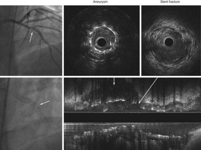
More recently, stent fracture is being implicated as a cause of DES failure, especially with SES. In a prior retrospective IVUS study of 17 non-STEMI patients with 20 stent strut fractures, 18 (90%) occurred in SES and 2 (10%) in BMS, but none in PES.101 Of note, 5 of 20 stent fractures were accompanied by coronary aneurysm formation with two very late stent thromboses (Fig. 7-14). It has been proposed that biologic reactions to the eluted drug cause positive vessel remodeling with aneurysm formation and malapposition that allow motion and/or kinking of the stent within the aneurysm, leading to strut fracture. Angiographic data from three PES trials in nonacute coronary syndromes revealed a 1.1% rate of stent fracture associated with restenosis and/or stent thrombosis.102 In the Nordic IVUS study, stent malapposition and stent fracture were found in 43% (37 of 87) and 16% (14 of 87) of DES thrombosis cases and 27% (10 of 37) and 27% (10 of 37) of BMS thrombosis cases.103
Treatment Of In-Stent Restenosis
The uses of IVUS in evaluating patients with in-stent restenosis include (1) determining whether in-stent restenosis is severe enough to treat, (2) identifying occult mechanical problems with the stent that (presumably) occurred at the time of implantation, (3) assessing the patterns of in-stent restenosis, and (4) assessing the acute results. Using integrated TAXUS data (331 treated with PES and 304 treated with BMS who did not require revascularization in the first 9 months postintervention), we reported that the optimal thresholds of MLA that best predicted subsequent target vessel revascularization-free survival during the subsequent 3 years were 4.2 mm2 for PES and 4.0 mm2 for BMS.104
There are a number of technical and mechanical complications of stent implantation that can remain unrecognized until the patient presents with in-stent restenosis. These include (1) missing the lesion, (2) stent underexpansion, (3) stent “crush,” and (4) having the stent stripped off the balloon during the implantation procedure. Because most stents are radiolucent, some lesions, especially aortoostial lesions, can be missed. Incomplete stent expansion during implantation can be missed angiographically because stents are porous and contrast can flow through and around them. Chronic stent recoil is rare.63,105 If the guidewire is accidentally removed and, in recrossing the freshly placed (and presumably not fully implanted) stent, it courses adjacent to the stent and enters the stent through one of the diamonds, subsequent adjunct balloon dilation can crush part of the stent against the vessel wall. These mechanical problems constitute a minority of in-stent restenoses. However, the treatment of in-stent restenosis must begin by excluding these problems and, if they are present, by correcting them. Examples are shown in Figures 7-15 and 7-16. In an analysis of more than 1000 consecutive in-stent restenosis lesions, the frequency of these mechanical complications was found to be 4% to 5%.106
Bioabsorbable Stents
The first generation of bioabsorbable everolimus-eluting stents (BVS) implanted in 30 simple de novo lesions showed higher acute recoil than conventional metallic platform stents. At 6 months, the 11.8% reduction in scaffold area (chronic recoil) and a small neointimal response of 5.5% resulted in a total 24.3% decrease in MLA by IVUS.107 However, at 2 years, the lumen area increased because of decrease in plaque size without change in vessel size.108 The second-generation BVS had an improved scaffold that had only a 2% chronic recoil.109
Does Ivus Guidance Reduce Stent Restenosis And Thrombosis?
A number of randomized and nonrandomized studies compared IVUS versus angiographic guidance of BMS implantation.110–112 A metaanalysis of the seven randomized IVUS versus angiography trials showed that IVUS improved final BMS dimensions to reduce BMS restenosis and repeat revascularization.112 In the DES era, Roy and co-workers reported that IVUS guidance reduced stent thrombosis both within 1 month and from 1 to 12 months (0.7% vs. 2.0% at 1 year, p = 0.014), supporting the use of IVUS during interventional procedures.113 The improvement of major adverse cardiac events, particularly mortality, has been supported by Park and colleagues in unprotected LMCA-treated arteries.114


1 Mintz GS, Nissen SE, Anderson WD, et al. ACC clinical expert consensus document on standards for the acquisition, measurement and reporting of intravascular ultrasound studies: a report of the American College of Cardiology Task Force on Clinical Expert Consensus Documents (Committee to Develop a Clinical Expert Consensus Document on Standards for Acquisition, Measurement and Reporting of Intravascular Ultrasound Studies [IVUS]). J Am Coll Cardiol. 2001;37:1478-1492.
2 Di Mario C, Görge G, Peters R, et al. Clinical application and image interpretation in intracoronary ultrasound. Eur Heart J. 1998;19:207-229.
3 Fitzgerald PJ, Goar FG, Connolly AJ, et al. Intravascular ultrasound imaging of coronary arteries. Is three layers the norm? Circulation. 1992;86:154-158.
4 Friedrich GJ, Moes NY, Mühlberger VA, et al. Detection of intralesional calcium by intracoronary ultrasound depends on the histologic pattern. Am Heart J. 1994;128:435-441.
5 Kostamaa H, Donovan J, Kasaoka S, et al. Calcified plaque cross-sectional area in human arteries: correlation between intravascular ultrasound and undecalcified histology. Am Heart J. 1999;137:482-488.
6 Mintz GS, Popma JJ, Pichard AD, et al. Patterns of calcification in coronary artery disease. A statistical analysis of intravascular ultrasound and coronary angiography in 1155 lesions. Circulation. 1995;91:1959-1965.
7 Prati F, Arbustini E, Labellarte A, et al. Intravascular ultrasound insights into plaque composition. Z Kardiol. 2000;89(Suppl 2):117-123.
8 Bridal SL, Forenès P, Bruneval P, Berger G. Correlation of ultrasonic attenuation (30 to 50 MHz) and constituents of atherosclerotic plaque. Ultrasound Med Biol. 1997;23:691-703.
9 Wu X, Maehara A, Mintz GS, et al. Virtual histology intravascular ultrasound analysis of non-culprit attenuated plaque detected by grayscale intravascular ultrasound in patients with acute coronary syndromes. Am J Cardiol. 2010;105:48-53.
10 Lee JB, Mintz GS, Lisauskas JB, et al. Histolopathologic validation of intravascular ultrasound diagnosis of a calcified coronary nodule, a type of plaque suspected to be vulnerable (abstract). Circulation. 2010;122:A21455.
11 Okubo M, Kawasaki M, Ishihara Y, et al. Development of integrated backscatter intravascular ultrasound for tissue characterization of coronary plaques. Ultrasound Med Biol. 2008;34:655-663.
12 Watson RJ, McLean CC, Moore MP, et al. Classification of arterial plaque by spectral analysis of in vitro radio frequency intravascular ultrasound data. Ultrasound Med Biol. 2000;26:73-80.
13 Nair A, Kuban BD, Tuzcu EM, et al. Coronary plaque classification with intravascular ultrasound radiofrequency data analysis. Circulation. 2002;106:2200-2206.
14 Nair A, Margolis MP, Kuban BD, Vince GD. Automated coronary plaque characterization with intravascular ultrasound backscatter: ex vivo validation. EuroInterv. 2007;3:113-120.
15 Stone GS, Maehara A, Lansky AJ, et al. A prospective natural-history study of coronary atherosclerosis. N Eng J Med. 2011;364:226-235.
16 Glagov S, Weisenberg E, Zarins CK, et al. Compensatory enlargement of human atherosclerotic coronary arteries. N Engl J Med. 1987;316:1371-1375.
17 Mintz GS, Painter JA, Pichard AD, et al. Atherosclerosis in angiographically “normal” coronary artery reference segments: an intravascular ultrasound study with clinical correlations. J Am Coll Cardiol. 1995;25:1479-1485.
18 Hausmann D, Erbel R, Alibelli-Chemarin M-J, et al. The safety of intracoronary ultrasound: A multicenter survey of 2207 examinations. Circulation. 1995;91:623-630.
19 Batkoff BW, Linker DT. The safety of intracoronary ultrasound: Data from a multicenter European registry. Catheter Cardiovasc Diagn. 1996;38:238-241.
20 Görge G, Peters RJG, Pinto F, et al. Intravascular ultrasound: Safety and indications for use in 7085 consecutive patients studied in 32 centers in Europe and Israel. J Am Coll Cardiol. 1996;27:155A.
21 Arnett EN, Isner JM, Redwood DR, et al. Coronary artery narrowing in coronary artery disease: Comparison of cineangiographic and necropsy findings. Ann Intern Med. 1979;91:350-356.
22 Waller BF. Anatomy, histology, and pathology of the major epicardial coronary arteries relevant to echocardiographic imaging techniques. J Am Soc Echocardiogr. 1989;2:232-252.
23 Isner JM, Donaldsen RF. Coronary angiographic and morphologic correlation. In: Waller BF, editor. Cardiac morphology. Philadelphia: Saunders; 1984:571-592.
24 Marcus ML, Skorton DJ, Johnson MR, et al. Visual estimates of percent diameter coronary stenosis: “A battered gold standard.”. J Am Coll Cardiol. 1988;11:882-885.
25 Hutchins GM, Bulkley BH, Ridolfi RL, et al. Correlation of coronary arteriograms and left ventriculograms with postmortem studies. Circulation. 1977;56:32-37.
26 Abizaid A, Mintz GS, Pichard AD, et al. Clinical, intravascular ultrasound, and quantitative angiographic determinants of the coronary flow reserve before and after percutaneous transluminal coronary angioplasty. Am J Cardiol. 1998;82:423-428.
27 Nishioka T, Amanullah AM, Luo H, et al. Clinical validation of intravascular ultrasound imaging for assessment of coronary stenosis severity: Comparison with stress myocardial perfusion imaging. J Am Coll Cardiol. 1999;33:1870-1878.
28 Takagi A, Tsurumi Y, Ishii Y, et al. Clinical potential of intravascular ultrasound for physiological assessment of coronary stenosis: Relationship between quantitative ultrasound tomography and pressure-derived fractional flow reserve. Circulation. 1999;100:250-255.
29 Abizaid AS, Mintz GS, Mehran R, et al. Long-term follow-up after percutaneous transluminal angioplasty was not performed based on intravascular ultrasound findings: importance of lumen dimensions. Circulation. 1999;100:256-261.
30 Tonino PA, De Bruyne B, Pijls NH, et al. Fractional flow reserve versus angiography for guiding percutaneous coronary intervention. N Eng J Med. 2009;360:213-224.
31 Hermiller JB, Buller CE, Tenaglia AN, et al. Unrecognized left main coronary artery disease in patients undergoing interventional procedures. Am J Cardiol. 1993;71:173-176.
32 Yamagishi M, Hongo Y, Goto Y, et al. Intravascular ultrasound evidence of angiographically undetected left main coronary artery disease and associated trauma during interventional procedures. Heart Vessels. 1996;11:262-268.
33 Gerber TC, Erbel R, Görge G, et al. Extent of atherosclerosis and remodeling of the left main coronary artery determined by intravascular ultrasound. Am J Cardiol. 1994;73:666-671.
34 Ge J, Liu F, Görge G, et al. Angiographically “silent” plaque in the left main coronary artery detected by intravascular ultrasound. Coron Artery Dis. 1995;6:805-810.
35 Fisher LD, Judkins MP, Lesperance J, et al. Reproducibility of coronary arteriographic reading in the Coronary Artery Surgery Study (CASS). Catheter Cardiovasc Diagn. 1982;8:565-575.
36 Isner JM, Kishel J, Kent KM, et al. Accuracy of angiographic determination of left main coronary arterial narrowing: Angiographic-histologic correlative analysis in 28 patients. Circulation. 1981;63:1056-1064.
37 Detre KM, Wright E, Murphy ML, et al. Observer agreement in evaluating coronary angiograms. Circulation. 1975;52:979-986.
38 DeRouen TA, Murray JA, Owen W. Variability in the analysis of coronary arteriograms. Circulation. 1977;55:324-328.
39 Zir LM, Miller SW, Dinsmore RE, et al. Interobserver variability in coronary angiography. Circulation. 1976;53:627-632.
40 Sanmarco ME, Brooks SH, Blankenhorn DH. Reproducibility of a consensus panel in the interpretation of coronary angiograms. Am Heart J. 1978;96:430-437.
41 Cameron A, Kemp HGJr, Fisher LD, et al. Left main coronary artery stenosis: angiographic determination. Circulation. 1983;68:484-489.
42 Flemming RM, Kirkeeide RL, Smalling RW, et al. Patterns in visual interpretation of coronary arteriograms as detected by quantitative coronary arteriography. J Am Coll Cardiol. 1991;18:945-951.
43 Abizaid AS, Mintz GS, Abizaid A, et al. One year follow-up after intravascular ultrasound assessment of moderate left main coronary artery disease in patients with ambiguous angiograms. J Am Coll Cardiol. 1999;34:707-715.
44 Jasti V, Ivan E, Yalamanchilli V, et al. Correlations between fractional flow reserve and intravascular ultrasound in patients with an ambiguous left main coronary artery stenosis. Circulation. 2004;110:2831-2836.
45 Hernandez JT, Hernandez FH, Runoroso JR, et al. Prospective application of predefined intravascular ultrasound criteria for revascularization of intermediate left main coronary artery lesions: results at 2 years from the LITRO study. http://ww3.aievolution.com/tct1001/files/content/abstracts/1615/344_DelaTorreHernandez.pps. Accessed January 23, 2011
46 Fuessl RT, Mintz GS, Pichard AD, et al. In vivo validation of intravascular ultrasound length measurements using a motorized transducer pullback device. Am J Cardiol. 1996;77:1115-1118.
47 Stone GW, Hodgson JMcB, Goar FG, et al. For the CLOUT Investigators. Improved procedural results of coronary angioplasty with intravascular ultrasound guided balloon sizing: The CLOUT Pilot Trial. Circulation. 1997;95:2044-2052.
48 Abizaid A, Pichard AD, Mintz GS, et al. Acute and long-term results of an IVUS-guided PTCA/provisional stent implantation strategy. Am J Cardiol. 1999;84:1381-1384.
49 Duissaillant GD, Mintz GS, Pichard AD, et al. Intravascular ultrasound identification of calcified intraluminal lesions misdiagnosed as thrombi by coronary angiography. Am Heart J. 1996;132:687689.
50 Maehara A, Mintz GS, Ahmed JM, et al. An intravascular ultrasound classification of angiographic coronary artery aneurysms. Am J Cardiol. 2001;88:365-370.
51 Maehara A, Mintz GS, Bui AB, et al. Morphologic and angiographic features of coronary plaque rupture detected by intravascular ultrasound. J Am Coll Cardiol. 2002;40:904-910.
52 Tsujita K, Maehara A, Mintz GS, et al. Comparison of angiographic and intravascular ultrasonic detection of myocardial bridging of the left anterior descending coronary artery. Am J Cardiol. 2008;102:1608-1613.
53 Maehara A, Mintz GS, Castagna MT, et al. Intravascular ultrasound assessment of spontaneous coronary artery dissection. Am J Cardiol. 2002;89:466-468.
54 Lee SY, Mintz GS, Kim SY, et al. Attenuated plaque detected by IVUS: Clinical, angiographic, and morphological features and post-percutaneous coronary intervention complications in patients with acute coronary syndrome. J Am Coll Cardiol Interv. 2009;2:65-72.
55 Okura H, Taguchi H, Kubo T, et al. Atherosclerotic plaque with ultrasonic attenuation affects coronary reflow and infarct size in patients with acute coronary syndrome. Circ J. 2007;71:648-653.
56 Endo M, Hibi K, Shimizu T, et al. Impact of ultrasound attenuation and plaque rupture as detected by intravascular ultrasound on the incidence of no-reflow phenomenon after percutaneous coronary intervention in ST-segment elevation myocardial infarction. J Am Coll Cardiol Interv. 2010;3:540-549.
57 Wu X, Mintz GS, Xu K, et al. Relationship between attenuated plaque identified by intravascular ultrasound and no-reflow after stenting in acute myocardial infarction: The HORIZONS-AMI trial. J Am Coll Cardiol Interv. 2011;4:495-502.
58 Higashikuni Y, Tanabe K, Tanimoto S, et al. Impact of culprit plaque composition on the no-reflow phenomenon in patients with acute coronary syndrome. An intravascular ultrasound radiofrequency analysis. Circ J. 2008;72:1235-1241.
59 Kawaguchi R, Oshima S, Jingu M, et al. Usefulness of virtual histology intravascular ultrasound to predict distal embolization for ST-segment elevation myocardial infarction. J Am Coll Cardiol. 2007;50:1641-1646.
60 Kawamoto T, Okura H, Koyama Y, et al. The relationship between coronary plaque characteristics and small embolic particles during coronary stent implantation. J Am Coll Cardiol. 2007;50:1635-1640.
61 Hong YJ, Jeong MH, Choi YH, et al. Impact of plaque components on no-reflow phenomenon after stent deployment in patients with acute coronary syndrome: a virtual histology-intravascular ultrasound analysis. Eur Heart J. 2011;32:2059-2066.
62 Maehara A, Mintz GS, Bui AB, et al. Incidence, morphology, angiographic findings, and outcomes of intramural hematomas after percutaneous coronary interventions. Circulation. 2002;105:2037-2042.
63 Hoffmann R, Mintz GS, Dussaillant GR, et al. Patterns and mechanisms of in-stent restenosis. A serial intravascular ultrasound study. Circulation. 1996;94:1247-1254.
64 Hoffmann R, Mintz GS, Pichard AD, et al. Intimal hyperplasia thickness at follow-up is independent of stent size: A serial intravascular ultrasound study. Am J Cardiol. 1998;82:1168-1172.
65 Hoffmann R, Mintz GS, Mehran R, et al. Intravascular ultrasound predictors of angiographic restenosis in lesions treated with Palmaz-Schatz stents. J Am Coll Cardiol. 1997;31:43-49.
66 Kasaoka S, Tobis JM, Akiyama T, et al. Angiographic and intravascular ultrasound predictors of in-stent restenosis. J Am Coll Cardiol. 1998;32:30-35.
67 Moussa I, Moses J, Di Mario C, et al. Does the specific intravascular ultrasound criterion used to optimize stent expansion have an impact on the probability of stent restenosis? Am J Cardiol. 1999;83:1012-1017.
68 Sonoda S, Morino Y, Ako J, et al. Impact of final stent dimensions on long-term results following sirolimus-eluting stent implantation. J Am Coll Cardiol. 2004;43:1959-1963.
69 Hong MK, Mintz GS, Lee CW, et al. Intravascular ultrasound predictors of angiographic restenosis after sirolimus-eluting stent implantation. Eur Heart J. 2006;27:1305-1310.
70 Doi H, Maehara A, Mintz GS, et al. Impact of post-intervention minimal stent area on 9-month follow-up patency of paclitaxel-eluting stents: An integrated intravascular ultrasound analysis from the TAXUS IV, V, and VI and TAXUS ATLAS Workhorse, Long lesion, and direct stent trials. J Am Coll Cardiol Interv. 2009;2:1269-1275.
71 Costa MA, Angiolillo DJ, Tannenbaum M, et al. Impact of stent deployment procedural factors on long-term effectiveness and safety of sirolimus-eluting stents (final results of the multicenter prospective STLLR trial). Am J Cardiol. 2008;101:1704-1711.
72 Liu J, Maehara A, Mintz GS, et al. An integrated TAXUS IV, V, and VI intravascular ultrasound analysis of the predictors of edge restenosis after bare metal or paclitaxel-eluting stents. Am J Cardiol. 2009;103:501-506.
73 Colombo A, Drzewiecki J, Banning A, et al. Randomized study to assess the effectiveness of slow- and moderate-release polymer-based paclitaxel-eluting stents for coronary artery lesions. Circulation. 2003;108:788-794.
74 Tanabe K, Serruys PW, Degertekin M, et al. Incomplete stent apposition after implantation of paclitaxel-eluting stents or bare metal stents: Insights from the randomized TAXUS II trial. Circulation. 2005;111:900-905.
75 Moses JW, Leon MB, Popma JJ, et al. Sirolimus-eluting stents versus standard stents in patients with stenosis in a native coronary artery. N Eng J Med. 2003;349:1315-1323.
76 Ako J, Morino Y, Honda Y, et al. Late incomplete stent apposition after sirolimus-eluting stent implantation. J Am Coll Cardiol. 2005;46:1002-1005.
77 Weissman NJ, Koglin J, Cox DA, et al. Polymer-based paclitaxel-eluting stents reduce in-stent neointimal tissue proliferation. J Am Coll Cardiol. 2005;45:1201-1205.
78 Weissman NJ, Ellis SG, Grube E, et al. Effect of the polymer-based, paclitaxel-eluting TAXUS Express stent on vascular tissue responses: a volumetric intravascular ultrasound integrated analysis from the TAXUS IV, V, and VI trials. Eur Heart J. 2007;28:1574-1582.
79 Serruys PW, Ruygrok P, Neuzner J, et al. A randomized comparison of an everolimus-eluting coronary stent with a paclitaxel-eluting coronary stent: the SPRIT II trial. EuroInterv. 2006;2:286-294.
80 Sakurai R, Bonneau HN, Honda Y, et al. Intravascular ultrasound findings in ENDEAVOR II and ENDEAVOR III. Am J Cardiol. 2007;100:71M-76M.
81 Miyazawa A, Ako J, Hongo Y, et al. Comparison of vascular response to zotarolimus-eluting stent versus sirolimus-eluting stent: Intravascular ultrasound results from ENDEAVOR III. Am Heart J. 2008;155:108-113.
82 Stone GW, Midei M, Newman W, et al. Comparison of an everolimus-eluting stent and a paclitaxel-eluting stent in patients with coronary artery disease. JAMA. 2008;299:1903-1913.
83 Waseda K, Miyazawa A, Ako J, et al. Intravascular ultrasound results from the ENDEAVOR IV trial. J Am Coll Cardiol Interv. 2009;2:779-784.
84 Kornowski R, Mintz GS, Kent KM, et al. Increased restenosis in diabetes mellitus after coronary interventions is due to exaggerated intimal hyperplasia: A serial intravascular ultrasound study. Circulation. 1997;95:1366-1369.
85 Cheneau E, Leborgne L, Mintz GS, et al. Predictors of subacute stent thrombosis. Results of a systematic intravascular ultrasound study. Circulation. 2003;108:43-47.
86 Fujii K, Carlier SG, Mintz GS, et al. Stent underexpansion and residual reference segment stenosis are related to stent thrombosis after sirolimus-eluting stent implantation. J Am Coll Cardiol. 2005;45:995-998.
87 Okabe T, Mintz GS, Buch AN, et al. Intravascular ultrasound parameters associated with stent thrombosis after drug-eluting stent deployment. Am J Cardiol. 2007;100:615-620.
88 Liu X, Doi H, Maehara A, et al. A volumetric intravascular ultrasound comparison of early drug-eluting stent thrombosis versus restenosis. J Am Coll Cardiol Interv. 2009;2:428-434.
89 Hong MK, Mintz GS, Lee CW, et al. Incidence, mechanism, predictors, and long-term prognosis of late stent malapposition after bare-metal stent implantation. Circulation. 2004;109:881-886.
90 Hong MK, Mintz GS, Lee CW, et al. Late stent malapposition after drug-eluting stent implantation. An intravascular ultrasound analysis with long-term follow-up. Circulation. 2006;113:414-419.
91 van der Hoeven BL, Liem SS, Jukema JW, et al. Sirolimus-eluting stents versus bare-metal stents in patients with ST-segment elevation myocardial infarction: 9-month angiographic and intravascular ultrasound results and 12-months clinical outcome. J Am Coll Cardiol. 2008;51:618-626.
92 Guo N, Maehara A, Mintz GS, et al. Incidence, mechanisms, predictors, and clinical impact of acute and late stent malapposition after primary intervention in patients with acute myocardial infarction. Circulation. 2010;122:1077-1084.
93 Cook S, Wenaweser P. Togni M, et al. Incomplete stent apposition and very late stent thrombosis after drug-eluting stent implantation. Circulation. 2007;115:2426-2434.
94 Alfonso F, Pérez-Vizcayno MJ, Ruiz M, et al. Coronary aneurysm after drug-eluting stent implantation. Clinical, angiographic, and intravascular ultrasound findings. J Am Coll Cardiol. 2009;53:2053-2060.
95 Hassan AKM, Bergheanu SC, Stijnen T, et al. Late stent malapposition risk is higher after drug-eluting stent compared with bare-metal stent implantation and associates with late stent thrombosis. Eur Heart J. 2010;31:1172-1180.
96 Cook S, Ladich E, Nakazawa G, et al. Correlation of intravascular ultrasound findings with histopathological analysis of thrombus aspiration in patients with very late drug-eluting stent thrombosis. Circulation. 2009;120:391-399.
97 Lee CW, Kang SJ, Park DW, et al. Intravascular ultrasound findings in patients with very late stent thrombosis after either drug-eluting or bare-metal stent implantation. J Am Coll Cardiol. 2010;55:1936-1942.
98 Kang SJ, Mintz GS, Park DW, et al. Tissue characterization of in-stent neointimal using intravascular ultrasound radiofrequency data analysis. Am J Cardiol. 2010;106:1561-1565.
99 Takano M, Yamamoto M, Inami S, et al. Appearance of lipid-laden intima and neovascularization after implantation of bare-metal stents. J Am Coll Cardiol. 2010;55:26-32.
100 Kashiwagi M, Kitabata H, Tanaka A, et al. Very late clinical cardiac event after MBS implantation: In vivo optical coherence tomography examination. J Am Coll Cardiol Imaging. 2010;3:525-527.
101 Doi H, Maehara A, Mintz GS, et al. Classification and potential mechanisms of intravascular ultrasound patterns of stent fracture. Am J Cardiol. 2009;103:818-823.
102 Popma JJ. Strut fractures after DES: Definitions, frequency, timing, device specificity, and associated clinical events. Transcatheter cardiovascular therapeutics. www.tctmd.com/txshow.aspx?tid=2532&id=73192&trid=2380. Accessed April 8, 2009
103 Kosonen P. Stent fracture, strut malapposition common in stent thrombosis cases. www.tctmd.com/Show.aspx?id=90294. Accessed January 23, 2011
104 Doi H, Maehara A, Mintz GS, et al. Impact of in-stent minimal lumen area at 9 months poststent implantation on 3-year target lesion revascularization free survival: A serial intravascular ultrasound analysis from the TAXUS IV, V, and VI trials. Circ Cardiovasc Interv. 2008;1:111-118.
105 Hong M-K, Park S-W, Lee CW, et al. Intravascular ultrasound comparison of chronic recoil among different stent designs. Am J Cardiol. 1999;84:1247-1250.
106 Castagna MT, Mintz GS, Weissman NJ, et al. The contribution of “mechanical” problems to in-stent restenosis. An intravascular ultrasound analysis of 1090 consecutive in-stent restenosis lesions. Am Heart J. 2001;142:970-974.
107 Ormiston JA, Serruys PW, Regar E, et al. A bioabsorbable everolimus-eluting coronary stent system for patients with single de-novo coronary artery lesions (ABSORB): a prospective open-label trial. Lancet. 2008;371:899-907.
108 Serruys PW, Ormiston JA, Onuma Y, et al. A bioabsorbable everolimus-eluting coronary stent system (ABSORB): 2-year outcomes and results from multiple imaging methods. Lancet. 2009;373:897-910.
109 Serruys PW, Onuma Y, Ormiston JA, et al. Evaluation of the second generation of a bioabsorbable everolimus drug-eluting vascular scaffold for treatment of de novo coronary artery stenoses. Circulation. 2010;122:2301-2312.
110 Fitzgerald PJ, Oshima A, Hayase M, et al. Final results of the Can Routine Ultrasound Influence Stent Expansion (CRUISE) study. Circulation. 2000;102:523-530.
111 Russo RJ, Silva PD, Teirstein PS, et al. A randomized controlled trial of angiography versus intravascular ultrasound-directed bare-metal coronary stent placement (The AVID trial). Circ Cardiovasc Interv. 2009;2:113-123.
112 Parise H, Maehara A, Stone GW, et al. A meta-analysis of randomized studies comparing intravascular ultrasound versus angiographic guidance of percutaneous coronary intervention in the pre-drug eluting era. Am J Cardiol. 2011;107:374-382.
113 Roy P, Steinberg DH, Sushinsky SJ, et al. The potential clinical utility of intravascular ultrasound guidance in patients undergoing percutaneous coronary intervention with drug-eluting stents. Eur Heart J. 2008;29:1851-1857.
114 Park SJ, Kim YH, Park DW, et al. Impact of intravascular ultrasound guidance on long-term mortality in stenting for unprotected left main coronary artery stenosis. Circ Cardiovasc Interv. 2009;2:167-177.
[/level-membership-for-cardiovascular-category][not-level-membership-for-cardiovascular-category]
7 Intravascular Ultrasound
Principles and Clinical Applications
Technical Background
Gray-Scale Intravascular Ultrasound
Gray-scale intravascular ultrasound (IVUS) utilizes one or more miniaturized transducers secured at the end of a flexible catheter that is inserted into arteries for in vivo tomographic visualization of vascular anatomy. Intracoronary ultrasound has become the most commonly used form of intravascular imaging and is regularly employed to delineate plaque morphology and distribution, to assess angiographically ambiguous lesions, to assess atherosclerosis progression and regression, to guide transcatheter coronary intervention, and to assess mechanisms of restenosis (Fig. 7-1).1–2 The IVUS catheter is attached to either a portable or installed ultrasound machine through an interface that ensures sterility of the catheter and allows for motorized pullback. Motorized pullback of the IVUS catheter (or of the transducer within the catheter) at 0.5 mm/s or 1.0 mm/s allows calculation of lesion length and plaque volumes (necessary for progression/regression studies), ensures adequate time to visualize the lesion, and allows comparison between IVUS “runs” done at different times but with similar pullback speeds.
Image Formation
An IVUS image is formed when ultrasound bounces off the multiple layers of the artery and returns to the transducer.3 The coronary artery is a muscular vessel composed of three basic layers: intima, media, and adventitia (Fig. 7-2). The intima, only a few cells thick at birth, is the site of atherosclerotic plaque accumulation. The intima is directly surrounded by the media, a layer of predominately homogeneous smooth muscle cells that provides the artery with its vascular tone. The outermost layer is the adventitia. Each of these layers tends to have a different acoustic property, allowing each to be visualized separately. When ultrasound encounters the intima, there is a large change in acoustic impedance; and much of it is bounced back to the transducer and displayed as a single concentric echo. Unless the intima becomes extremely hard, such as with the formation of a calcified plaque, some ultrasound penetrates through to the media. Because the media is composed of homogeneous smooth muscle cells, it passes through with minimal reflection; thus the media appears as a dark zone devoid of echoes. The adventitia has numerous layers of collagen fibers and therefore is a highly reflective structure that appears bright. As a result of the different acoustic properties of each layer, the normal coronary artery has a three-layered appearance, which includes (1) a bright echo from the intima, (2) a dark zone from the media, and (3) bright echoes from the adventitia. Because the resolution of IVUS is approximately 100 to 120 µm, the intima has to be at least this thick to be visualized as a distinct structure. In Western society, most patients presenting to the cardiac catheterization laboratory have some diffuse thickening of the intima. But if the intima is truly disease free, as in a newborn, child, or adolescent, then the intima will be much thinner and below the resolution of IVUS so that the artery will appear as a monolayer (see Fig. 7-2).
Image Interpretation
The interpretation of an IVUS image involves only a few simple steps: (1) identify the IVUS catheter in the center of the screen, keeping in mind that the IVUS catheter is traveling down the blood-filled lumen; (2) identify the dark stripe of the media that tells the size of the artery in the absence atherosclerotic disease; (3) remember that all of the echoes within the media stripe represent intima or intimal (atherosclerotic) disease and (4) all of the echoes outside the media are adventitia (see Fig. 7-2).
The amount of ultrasound that reflects off of tissue depends on the acoustic impedance (density) of the tissue. This property provides IVUS with some ability to differentiate plaque of different compositions. Hard material (calcium or fibrotic plaque) will reflect more ultrasound and appear brighter, whereas soft plaque (fat) will not reflect the ultrasound and will appear dark. Calcium is so dense that no ultrasound penetrates to the deeper tissues and, thus, produces acoustic shadows; shadowing, along with the bright echoes is the hallmark of calcification. A conventional approach is to compare the overall brightness of the plaque to the surrounding adventitia. Plaque is typically characterized as hypoechoic if less dense than the adventitia, hyperechoic if more dense than the adventitia, calcified if bright with acoustic shadowing, or mixed. IVUS can detect dense calcium with high sensitivity and specificity,4–6 but its accuracy in identifying high-risk lipid rich plaque or even thrombus formation is poor.7 As shown in Figure 7-3, gray-scale IVUS can also detect two other types of high-risk plaques: (1) noncalcified attenuated plaque (which correlates with fibroatheroma) and (2) calcium nodules (calcium with a convex shape and irregular surface).8–10
Radiofrequency Ivus
Standard gray-scale IVUS is limited, in part, because it uses only the amplitude of reflected ultrasound to formulate the image. In an effort to improve on the qualitative assessment of the reflected ultrasound signal, Kawasaki and coworkers developed a plaque characterization algorithm called integrated backscatter IVUS using time domain information directly from the radiofrequency signal. This process has resulted in improved plaque characterization with a reported in vitro sensitivity of 90% and specificity or 92% for lipid-rich plaque.11
In a similar effort to improve plaque characterization, spectral analysis (virtual histology [VH]-IVUS) combines signal frequency and amplitude analysis to create an algorithm that detects fibrous tissue (dark green), fibrofatty (light green), necrotic core (red), and dense calcium (white). Reported sensitivity and specificity of VH-IVUS are 91.7% and 96.6% for identification of the lipid-rich necrotic core.12–14 However, VH-IVUS cannot detect thrombus (in fact, thrombus appears as either fibrotic or fibrofatty plaque depending on the age of the thrombus) and has not been validated for assessment of stent metal or intimal hyperplasia. VH-IVUS lesion phenotype has been classified as (1) VH thin-cap fibroatheroma, (2) thick-cap fibroatheroma, (3) pathologic intimal thickening, (4) fibrotic plaque, and (5) fibrocalcific plaque (Fig. 7-4). Fibrotic plaque has mainly fibrous tissue with less than 10% confluent necrotic core, less than 10% confluent dense calcium, less than 15% fibrofatty. Fibrocalcific plaque has mainly fibrous tissue with greater than 10% confluent dense calcium, but less than 10% confluent necrotic core. Pathologic intimal thickening has a mixture of all plaque components, but dominantly fibrofatty with less than 10% confluent necrotic core and less than 10% confluent dense calcium. Fibroatheroma (both VH thin-cap fibroatheroma and thick-cap fibroatheroma) has greater than 10% confluent necrotic core. Because the resolution of VH-IVUS is 150 to 250 µm, it is not possible to detect fibrous cap thickness less than 65 µm (the typical pathologic definition of a thin fibrous cap). Therefore, if there is greater than 30° of necrotic core abutting to the lumen in three consecutive slices, the fibroatheroma is classified as VH thin-cap fibroatheroma; otherwise, it is classified as thick-cap fibroatheroma.15
Ivus Versus Angiography
It has been verified in autopsy studies and other IVUS studies of healthy donors that most people have diffuse atherosclerotic disease throughout their arteries by midlife, and this disease often remains angiographically silent because of its diffuse nature. In addition to diffuse plaque, vascular remodeling is also responsible for the high prevalence of angiographically silent disease. Both pathology and IVUS studies have documented that coronary arteries will enlarge to accommodate focal plaque deposition in an attempt to maintain luminal integrity. Compensatory dilation of the arterial wall occurs in direct response to the accumulation of atherosclerotic plaque. An absolute reduction in lumen dimensions typically does not occur until the lesion occupies approximately 40% to 50% of the area within the internal elastic membrane (40% to 50% cross-sectional narrowing).16 As a result, most of the atherosclerotic burden is contained within angiographically normal reference segments.17
Clinical Applications
Safety
Three large studies have evaluated the safety of IVUS. Other than transient spasm, complications appear to be rare (Table 7-1).18–20
Assessment Of Stenosis Severity
Coronary angiography underestimates stenosis severity most markedly in vessels with 50% to 75% plaque burden (plaque area divided by arterial area) at necropsy and in patients with multivessel disease.21–25 Clinical events are determined by lumen size, not by the amount of plaque. Therefore, it is important to focus on accurate measurement of lumen dimensions and not to be distracted by the plaque burden. Plaque burden in patients with atherosclerosis tends to be large even in the absence of lumen compromise.
Studies performed more than 10 years ago suggested that an IVUS minimum lumen area (MLA) greater than 4 mm2 was a valid criterion for deferring an intervention based both on comparisons to physiologic measures and on follow-up data.26–29 This cutoff only applied to major epicardial vessels excluding the LMCA and excluding saphenous vein grafts. However, it was necessary to interrogate the lesion carefully to identify the image slice with the smallest lumen, especially in very focal stenoses. Once the smallest lumen is identified, careful measurement was required. Recently this cutoff has come under criticism for a number of reasons including the size of the vessels (studies were done mostly in large 3.5-mm vessels), the average MLA of the intermediate lesions studied (4 mm2), and the fact that these studies have been misinterpreted to suggest that lesions with an MLA below 4 mm2 justify stent implantation. For this reason, it is recommended that for major epicardial vessels excluding the LMCA, physiologic lesion assessment (using an intracoronary pressure wire and maximum hyperemia with intravenous adenosine to measure the fractional flow reserve) is a complementary approach to assess lesion severity.30
Assessment Of Lmca Disease
A high percentage of patients with angiographically “normal” LMCA with only nonsignificant stenosis have substantial disease by IVUS.31–34 Reasons for the discrepancy between angiography and necropsy or IVUS assessment of LMCA disease include the following: (1) diffuse atherosclerotic involvement affects the angiographic diameter stenosis (DS) calculation because of the lack of a normal reference segment; (2) a short LMCA also makes identification of a normal reference segment difficult; (3) unique geometric issues exist in LMCA disease (the correlation between angiography and necropsy or IVUS appears to be somewhat better in non-LMCA stenoses); and (4) there is significant interobserver and intraobserver variability in the angiographic assessment of LMCA disease.35–42 In fact, the LMCA is the coronary arterial segment with the greatest variability in angiographic assessment.
[/not-level-membership-for-cardiovascular-category]
