21 Intracardiac Echocardiography
Intracardiac echocardiography has evolved over the last 10 years into a major adjunct imaging modality in the catheterization laboratory to guide procedures, primarily those associated with the atrial septum and pulmonary veins.1,2 Because of the unique imaging perspective from within the heart, primarily from the right atrium, it also is useful in assessing the aortic valve and left ventricular outflow tract in patients who are hard to image via transthoracic or transesophageal echocardiography due to shadowing from prosthetic mechanical valves. Recently, it has been used to guide more complicated interventional procedures such as pulmonary valve implantation3 and atrial appendage occluder placement.4
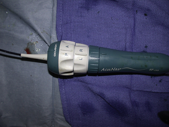
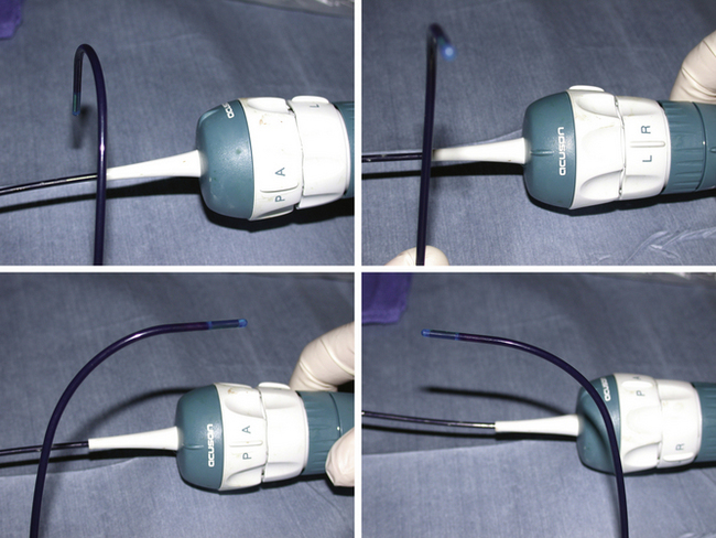
Intracardiac echocardiography (ICE) catheters, currently available in 8-French (8F) and 10-French (10F) sizes, consist of a single phased-array transducer on the tip of a steerable catheter. The handle has two control rings, anterior–posterior flexion, and right–left flexion, as well as a locking ring to hold the tip in position once flexed (Fig. 21-1). They connect to a standard compatible echocardiography machine with a full range of imaging capabilities, including two-dimensional, color Doppler, pulsed and continuous Doppler, and three-dimensional imaging (catheter specific). The catheter is wetted, and the catheter handle is covered with a sterile drape, connected to the echo machine, and tested (by inserting the tip in a bowl of saline to image) before it is inserted through a compatible venous sheath (Fig. 21-2). Most catheterization laboratories find direct control by the catheterizing operator most efficient, although some have an echocardiography technician or echocardiographer involved. The echocardiography machine should be slaved to a monitor on the main monitor bank to allow easy viewing by the catheterizer in conjunction with fluoroscopy images.
Technique
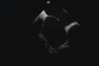
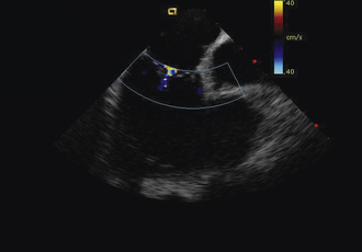
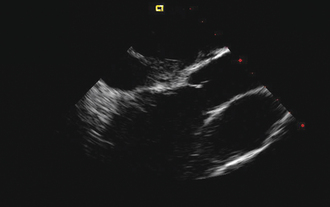
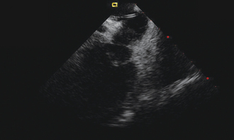
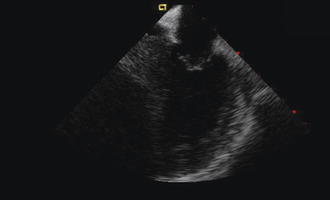
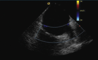
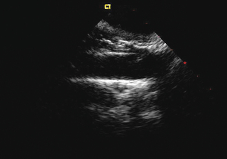
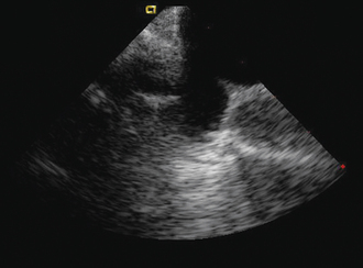
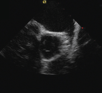
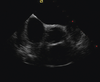
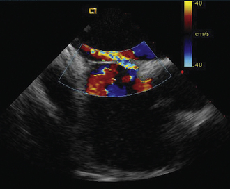
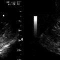
Having a standard approach/routine for imaging all cardiac structures is useful. By convention, the image is oriented with the proximal (handle) end of the transducer on the left side of the screen and the distal (tip) of the transducer on the right (Fig. 21-3). This can be adjusted in unusual circumstances, such as the patient illustrated in Figure 21-4, who had atrial septal defect, dextrocardia, and inferior vena cava interruption, so that the ICE catheter had to be inserted from the superior vena cava. The catheter tip is positioned in the low right atrium without flexion. To orient the catheter and all subsequent manipulations, we rotate the catheter handle until the tricuspid valve is centered on the image (Fig. 21-5). This is considered the “home” position, with no flexion on the tip. We return to this position anytime we lose our catheter/image orientation. Once in this home position, we can move the catheter through a simple clockwise rotation sweep without any catheter tip flexion to assess nearly all the cardiac structures of interest. Manipulations are subtle, as a small rotation at the handle will change the echocardiography beam view dramatically. From the “home” tricuspid valve position we rotate slightly clockwise to see the aortic valve and pulmonary valve in long-axis view (Fig. 21-6). Additional clockwise rotation brings the posterior aspect of the mitral valve in view (Fig. 21-7). To achieve better imaging of the mitral valve, slight anterior flexion may be necessary (Fig. 21-8). Return the anterior flexion to neutral and continue in the clockwise direction to see the left atrial appendage (Fig. 21-9), followed by the left superior and inferior pulmonary veins (Fig. 21-10). For these views, the catheter often needs to be advanced more superior into the right atrium. Remember that with the catheter inserted from the femoral vein, advancing the catheter into the body will view more superior structures, whereas withdrawing the catheter out of the body will view more inferior structures. Further clockwise rotation will image the posterior wall of the left atrium and the midportion of the right pulmonary artery behind it (Fig. 21-11). The final image of the basic sweep is an additional clockwise rotation to image the right pulmonary veins. Unlike the left veins, where the beam of the catheter is parallel to the axis of the veins (giving a long tubular image of the vein), the beam of the catheter imaging the right veins is perpendicular to the axis of the veins. This results in the veins appearing as circles budding off the LA (Fig. 21-12). To better image these veins, additional posterior flexion can be added to the catheter, aligning the beam with the axis of the veins (Fig. 21-13). That completes the standard sweep through the heart.
To image the atrial septum in detail, the catheter is rotated without flexion between the aortic and mitral valve positions. At this point, maximal posterior flexion is applied to the catheter. This will bring the aortic valve into cross section (Fig. 21-14). The catheter is withdrawn form the body slightly to center the atrial septum in the image (Fig. 21-15). The right–left ring is then used to sweep the echo beam through the entire septum. Right flexion will angle the beam toward the rightward anterior–superior septum at the superior vena cava junction (Fig. 21-16). Left flexion will angle the beam leftward, posterior, and inferior toward the crux of the heart at the atrioventricular valves (Fig. 21-17).
Specific Indications
Diagnosis of Left Ventricular Outflow Tract Obstruction in Patients with Prosthetic Valves
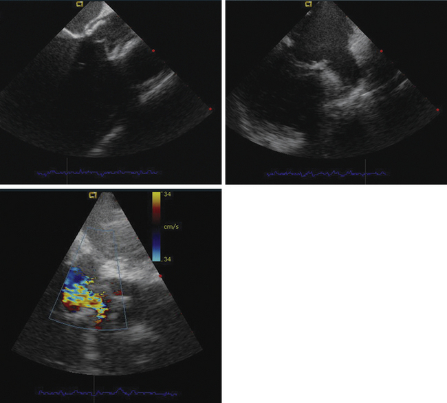
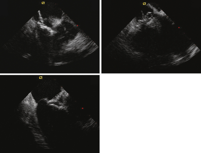
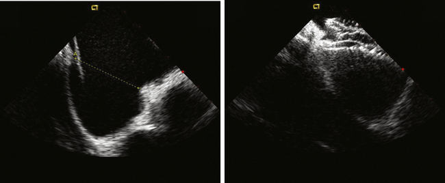
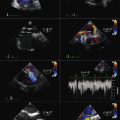
ICE can be helpful in patients with a prosthetic mitral or aortic valve, or both, in whom the left ventricular outflow tract or inferior aspect of the mechanical aortic valve needs to be imaged. Shadowing from the prosthetic valves, a common problem with either surface or transesophageal imaging, can be minimized with ICE imaging. Fig. 21-18 shows a series of ICE images in a patient with a prosthetic aortic valve and mitral annuloplasty who developed subaortic stenosis confirmed with ICE.
Patent Foramen Ovale Device Closure
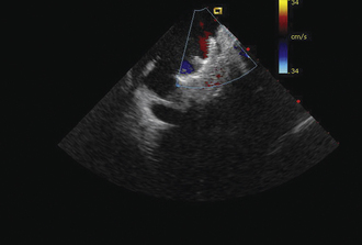
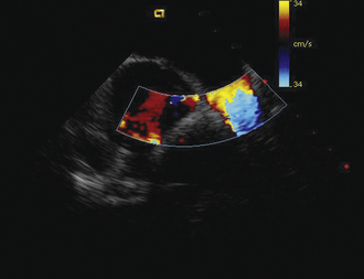
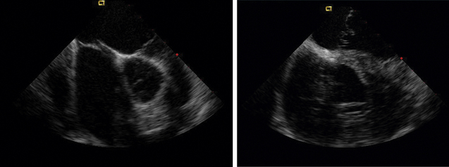
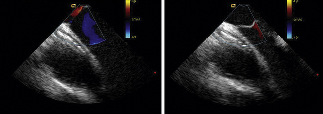
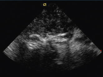
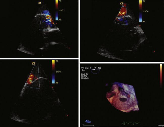
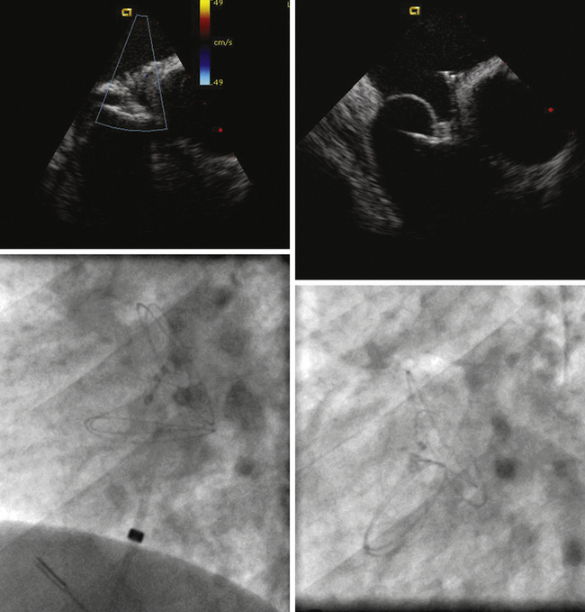
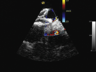
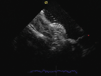
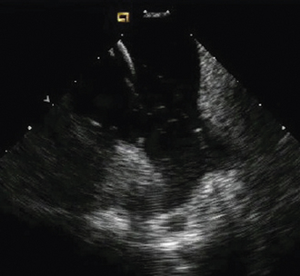
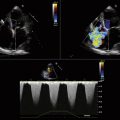
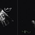
Detailed imaging of the atrial septum is possible with ICE, allowing evaluation of the septum primum, septum secundum, and degree of overlap or length of tunnel, as well as the presence of a left-to-right shunt by color Doppler5,6 (Fig. 21-19). The presence of an atrial septal aneurysm of the septum primum (Fig. 21-20) and any associated Chiari malformation (Fig. 21-21) can easily be identified. Device delivery can be monitored during placement to ensure appropriate positioning of the left atrial disc and right atrial disc (Fig. 21-22) and post release). Contrast saline echocardiography can be performed to evaluate for right-to-left shunting (Fig. 21-23). Less agitated saline should be used, because the contrast surrounding the imaging catheter tip can cause artifact that overwhelms the image. Patent foramen ovale or anterior septal defect with associated fenestrated defects (Fig. 21-24) can be detected and the procedure modified to ensure a successful outcome, as in the patient illustrated in Figure 21-25 in whom three HELEX septal occluder devices (Gore Medical) were implanted for complete closure. Because the resolution of the images allows imaging of exceptional detail, subtle and not-so-subtle abnormalities of device position (Fig. 21-26) or clot formation on a catheter or wire (Fig. 21-27) allow adjustment in procedural technique to optimize outcome.
Atrial Septal Defect Device Closure
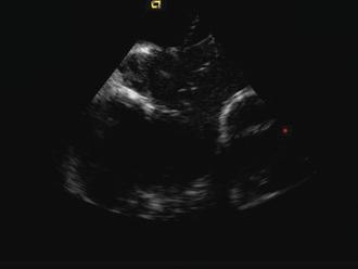
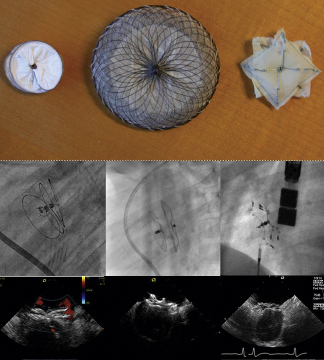
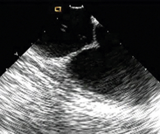
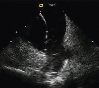
As with patent foramen ovale closure, ICE is an effective imaging technique for guidance of device closure of atrial septal defects.7,8 Multiple defects (see Figs. 21-21 to 21-24), presence or absence of inferior rim (Fig. 21-28), aortic knob rim (Fig. 21-29), and superior rim (Fig. 21-30) can be imaged accurately. As with a patent foramen ovale closure, ICE facilitates measurement of balloon test occlusion (Fig. 21-31) as well as ASD device placement. Post-placement assessment for appropriate position and residual leak (Fig. 21-32) as well as encroachment on the AV valves (Fig. 21-33) should be performed. All currently used device types are well imaged with ICE (Fig. 21-34).
Transseptal Puncture
ICE allows guidance of puncture relative to other structures in complex left-sided interventional procedures when transseptal puncture is needed (Fig. 21-35), and when puncture must be located for optimal positioning of the LA sheath. Procedures for which ICE guidance is extremely helpful include atrial fibrillation, pulmonary vein ablation (inferior posterior aspect of the septum), and mitral perivalvar leak embolization (superior anterior aspect of the septum).
Radiofrequency Ablation for Atrial Fibrillation
ICE imaging allows specific assessment of pulmonary vein anatomy such as a confluent orifice of the left upper and lower pulmonary veins (Fig. 21-36) versus separate openings. These anatomic details, in addition to catheter localization (Fig. 21-37), make ICE a useful adjunct for ablation procedures.9,10 Some centers have used ICE imaging to evaluate cavitation formation during radiofrequency energy application to guide the ablation procedure.11 Recent work has been done integrating ICE images with three-dimensional CT images to optimize mapping.12
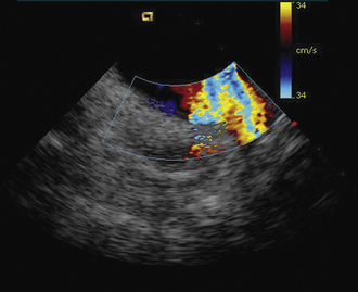
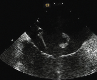
Figure 21-10 Additional clockwise rotation shows the left upper and lower pulmonary veins entering the left atrium.
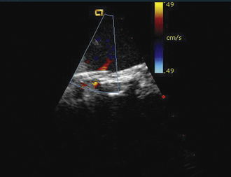
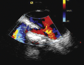
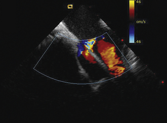
Figure 21-25 Intracardiac echocardiographic image corresponding to the lower left image shown in Figure 21-24 after implantation of three HELEX septal occluder devices. Trace residual leak is seen between the two most inferior devices.
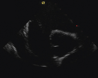
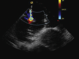
Figure 21-29 Intracardiac echocardiographic image showing a large atrial septal defect with absent aortic rim.
1. Bartel T., Konorza T., Arjumand J., et al. Intracardiac echocardiography is superior to conventional monitoring for guiding device closure of interatrial communications. Circulation. 2003;107:795-797.
2. Ren J.F., Marchlinski F.E., Callans D.J., Herrmann H.C. Clinical use of AcuNav diagnostic ultrasound catheter imaging during left heart radiofrequency ablation and transcatheter closure procedures. J Am Soc Echocardiogr. 2002;15:1301-1308.
3. Chessa M., Butera G., Carminati M. Intracardiac echocardiography during percutaneous pulmonary valve replacement. Eur Heart J. 2008;29:2908.
4. Vaina S., Ligthart J., Vijayakumar M., et al. Intracardiac echocardiography during interventional procedures. EuroIntervention. 2006;1:454-464.
5. Rigatelli G., Cardaioli P., Dell’Avvocata F., et al. The association of different right atrium anatomical-functional characteristics correlates with the risk of paradoxical stroke: an intracardiac echocardiographic study. J Interv Cardiol. 2008;21:357-362.
6. Opotowsky A.R., Landzberg M.J., Kimmel S.E., Webb G.D. Percutaneous closure of patent foramen ovale and atrial septal defect in adults: the impact of clinical variables and hospital procedure volume on in-hospital adverse events. Am Heart J. 2009;157:867-874.
7. Rigatelli G., Cardaioli P., Giordan M., et al. Transcatheter intracardiac echocardiography-assisted closure of interatrial shunts: complications and midterm follow-up. Echocardiography. 2009;26:196-202.
8. Zanchetta M., Rigatelli G., Pedon L., et al. Transcatheter atrial septal defect closure assisted by intracardiac echocardiography: 3-year follow-up. J Interv Cardiol. 2004;17:95-98.
9. Saliba W., Thomas J. Intracardiac echocardiography during catheter ablation of atrial fibrillation. Europace. 2008;10(suppl. 3):42-47. iii
10. Lakkireddy D., Rangisetty U., Prasad S., et al. Intracardiac echo-guided radiofrequency catheter ablation of atrial fibrillation in patients with atrial septal defect or patent foramen ovale repair: a feasibility, safety, and efficacy study. J Cardiovasc Electrophysiol. 2008;19:1137-1142.
11. Alaeddini J., Wood M.A., Lee B.P., Ellenbogen K.A. Incidence, time course, and characteristics of microbubble formation during radiofrequency ablation of pulmonary veins with an 8-mm ablation catheter. Pacing Clin Electrophysiol. 2006;29:979-984.
12. den Uijl D.W., Tops L.F., Tolosana J.M., et al. Real-time integration of intracardiac echocardiography and multislice computed tomography to guide radiofrequency catheter ablation for atrial fibrillation. Heart Rhythm. 2008;5:1403-1410.


