6 Intracardiac Echocardiography
Equipment and Handling Procedures
Guiding Device Closure of Interatrial Communications
Monitoring of Percutaneous Left Atrial Appendage Closure
Guiding Radiofrequency Pulmonary Vein Ablation
Monitoring Transcatheter Aortic Valve Implantation
Perioperative and Periinterventional Imaging of the Ascending Aorta
Periinterventional Imaging of the Descending Thoracic Aorta
During the past decade, intracardiac echocardiography (ICE) has become a standard guiding approach in interventional treatment of structural heart disease,1 such as in device closure of interatrial communications, percutaneous transluminal septal myocardial ablation, pulmonary vein ablation, percutaneous left atrial appendage closure, and recently in transcatheter aortic valve implantation (TAVI). With the introduction of the 8F AcuNav catheter (Acuson Siemens, Mountain View, Calif.), which is also used for ICE,2 intraaortic phased-array imaging (IPAI) became feasible. Guidance by fluoroscopy alone is limited because it cannot distinguish soft tissues and does not allow cross-sectional imaging. Consequently accurate positioning of devices can be difficult without echocardiographic guidance.2a On the other hand, distant posterior areas are difficult to depict with transthoracic echocardiography, especially when the patient is supine. Although transesophageal echocardiography (TEE) including real-time three-dimensional (3D) imaging is a well established diagnostic tool and provides exceptional high-resolution images, TEE’s usefulness for interventional procedures is not always ideal (see Chapter 5). However, evidence that ICE guidance can improve the safety of these procedures is still lacking.
Miniaturized ultrasound-tipped catheter devices were primarily introduced for intravascular use. The first attempts to percutaneously introduce intravenous probes with built-in echo transducers for in vivo intracardiac imaging were reported in the late 1960s. During the following two decades, several intracardiac echocardiographic catheters were developed. Later, intravascular ultrasound (IVUS) was employed to image coronary arteries as well as the aorta and peripheral vessels (see Chapter 7). IVUS-based intracardiac imaging was also used for guiding electrophysiologic procedures. Nevertheless, intracardiac IVUS lacks Doppler capabilities and is further limited by inadequate ultrasound penetration. For current noncoronary percutaneous interventions in structural heart disease, high-quality near-field images as well as Doppler flow analysis are a prerequisite for optimal results and also aid in avoiding and detecting complications. Thus, technical advances led from IVUS to the development of ICE and IPAI. Using these methods as a guiding tool in noncoronary percutaneous interventions is justifiable on the basis of improved procedural success and reduced complications, although costs of the catheter and reimbursement are problematic in many countries. In particular, progress in electrophysiologic ablation is clearly linked to the advances made with ICE.3 ICE and IPAI are also exciting research tools. Transfer of the methodology from the realm of research to routine clinical use is ongoing, such as in TAVI.4
Equipment and Handling Procedures
Current devices (Acuson, Mountain View, Calif.) are multimodal, phased-array transducer-tipped intracardiac echocardiographic catheters. Nowadays, the 8 F AcuNav catheter has become the tool of choice for ICE. Other devices have been introduced5 but have gained only limited acceptance (Table 6-1).
TABLE 6-1 Presently Available Intracardiac Echocardiographic Devices
| Catheters | Company | Features |
|---|---|---|
| UltraICE | Boston Scientific | Rotational, nonsteerable |
| EP Med View Flex | St. Jude Medical | Side-looking, 10 Fr, 2-8 MHz |
| ClearICE | St. Jude Medical | Side-looking, steerable, 3D localization |
| AcuNav | Siemens/Biosense-Webster | Side looking, steerable, 8 Fr and 10 Fr |
| SoundStar | Siemens/Biosense-Webster | Side-looking, steerable, 10 Fr, 3D localization |
In comparison to the 10-Fr version, the 8-Fr AcuNav catheter has facilitated ICE and increased patient comfort and probably safety as well. After its introduction in pediatric cardiology,2 the 8-Fr ICE catheter now is also used in adult interventional cardiology. The catheter possesses the unlimited echocardiographic capabilities of its predecessor but is available with more insertable length and in a shorter version. Besides two-dimensional (2D) and M-mode imaging, the ICE catheter also permits functional analysis. It possesses complete Doppler capabilities, including pulsed wave, continuous wave, color flow, and tissue Doppler modalities (Table 6-2).
TABLE 6-2 Doppler Imaging Modes and Frequencies of the Intracardiac Echocardiographic Catheter Family
| Catheter versions | 10 F | 8 F |
| Insertable length | 90 cm | 90 cm (formerly 110 cm) |
| Steering | Four-way | Four-way |
| 2D imaging frequency | 5.0-10.0 MHz | 5.0-10.0 MHz |
| Color Doppler frequency | 4.0-7.0 MHz | 4.0-7.0 MHz |
| CW Doppler | 5.0 MHz | 5.0-5.2 MHz |
| PW Doppler | 4.0-5.0 MHz | 4.0-5.0 MHz |
| Recommended access sheaths | 11 Fr | 8 or 9 Fr |
| Penetration | 15 cm | 15 cm |
PW, Pulsed wave.
Practical Tips
• Use long access sheaths to avoid injuring the pelvic veins during navigation.
• Use fluoroscopy as a precaution to safely advance the bidirectionally steerable (but guidewireless) catheter into the heart.
• Infuse 500 mL saline solution to dilate the veins and to facilitate catheter passage. Added benefit: reduced tendency for vagal responses when both the left and the right femoral veins need to be punctured.
To permit adequate imaging of the interatrial septum and its neighboring structures, two standardized views are used: (1) a transatrial longitudinal view showing the extent of the atrial septum from cranial to its distal margins—this view is seen with the catheter retroflexed inside the RA; and (2) a perpendicular transatrial short-axis view for visualizing the anterior part of the atrial septum and the transition to the aortic valve and the ascending aorta (Fig. 6-1).
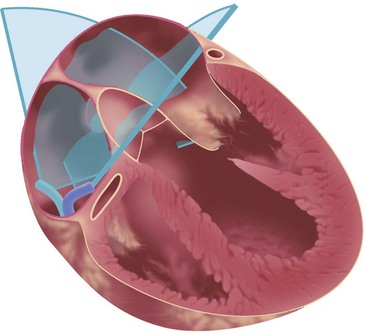
Figure 6-1 Standard transatrial views for intracardiac imaging are obtained with the catheter tip in the RA.
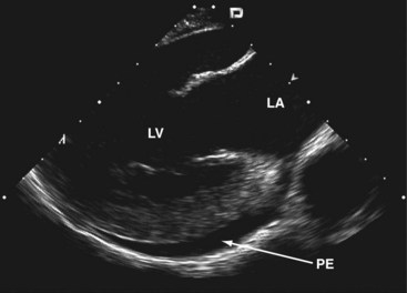
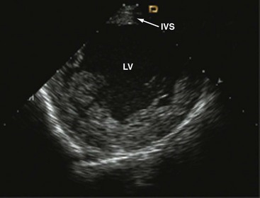
Clockwise rotation of the straightened ICE catheter permits visualization of the smallest anatomic details in the near field as well as to a depth of up to 12 cm. In order to enter the right ventricle, the tip of the probe is positioned in the mid to upper RA with the piezoelectric crystal facing the free wall of the RA, before the probe is gradually deflected anteriorly. From the right ventricle, the transventricular long-axis view of the left ventricle (LV) is obtained, which shows the interventricular septum proximally, the LV outflow tract, and the mitral valve apparatus. When the catheter tip is tilted to the right, the transventricular short-axis view of the LV comes into view (Figs. 6-2 and 6-3).
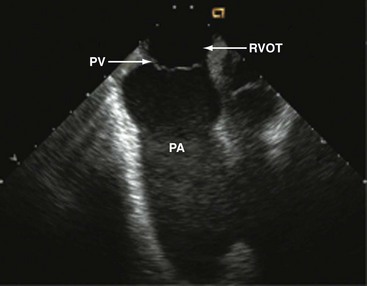
Interpretation of LV wall motion from transventricular views requires care because the catheter is moving inside the RV. By tilting the catheter tip away from the transventricular long-axis view, the RV outflow tract and pulmonary valve can be visualized as well (Fig. 6-4).
To avoid ventricular arrhythmias, the catheter has to be carefully navigated inside the RV cavity. The catheter should not be advanced beyond the pulmonary valve. When using the SVC approach, inadvertent catheter passage into the coronary sinus has to be avoided by all means. A certain expertise in intracardiac catheter manipulation is essential to safely advance the catheter into the right heart, to orient oneself inside the heart, to obtain standardized views, and to adequately visualize the cardiac anatomy6 (Table 6-3; also see Fig. 6-1).
| Window | Catheter Position | Standardized Cut Plane |
|---|---|---|
| Transatrial | RA | Longitudinal, craniocaudal view of IAS, LA, LAA |
| RA | Short-axis view of the anterior IAS, aortic valve, and ascending aorta | |
| RA | Longitudinal view of the RV, showing TV, RV | |
| Transventricular | RV | Long-axis view of the LV, IVS, LVOT, LA including LAA |
| RV | Short-axis view of the LV | |
| Transvenous | IVC | Aortic view of the abdominal aorta and its side branches |
| SVC/RA | Aortic view of the ascending aorta and aortic valve | |
| Intraaortic | Aorta | Imaging from inside the whole aorta including aortic arch |
| Aorta | Long-axis view of the aortic valve seen from the aortic arch |
IAS, Interatrial septum; IVC, inferior vena cava; IVS, interventricular septum; LAA, left atrial appendage; LVOT, left ventricular outflow tract; TV, tricuspid valve.
Guiding Device Closure of Interatrial Communications
Device closure of interatrial communications is performed for treatment of severe left-to-right shunts associated with atrial septal defects (ASDs) (see Chapter 44) and for prevention of recurrent paradoxical embolism in patients with a patent foramen ovale (see Chapter 41). Some complications with closure of interatrial communications are due to suboptimal device performance.7 Others, however, may be related to discontinuous echocardiographic monitoring, because supine patients do not tolerate continuous monitoring with TEE well unless they are sedated or under general anesthesia. More than 10 years of experience make us believe that some specific complications of transcatheter closure can potentially be avoided with improved echocardiographic monitoring. In that respect, ICE can be recommended as the method of choice for guiding percutaneous device closure, especially of ASDs.
Before passing instrumentation through the interatrial communication, the ICE catheter is advanced through the inferior vena cava into the RA. The transducer is aimed at the left atrium (LA) to obtain the transatrial longitudinal view. As a first step, adequate position of a long guidewire in the left superior pulmonary vein is demonstrated. The left superior pulmonary veins are depicted by angulating the probe from the longitudinal view inferiorly. The stretched size of ASDs can be adequately measured by ICE; however, sizing balloons must still be used—a mandatory step for estimating the size of the communication before ASD device closure.8
Practical Tips
• ICE displays release of the left-sided counteroccluder opening in the LA.
• The whole system including the long access sheath with the delivery cable inside and the opened left-sided counteroccluder is slightly pulled back until the open counteroccluder applies some traction on the atrial septum. ICE depicts the moment when the left-sided counteroccluder is closely aligned with the atrial septum.
• With the delivery cable still under traction, the long access sheath is further withdrawn to release the right-sided counteroccluder. ICE demonstrates release of the right-sided counteroccluder inside the RA and the left-sided counteroccluder remaining on the left side of the septum.
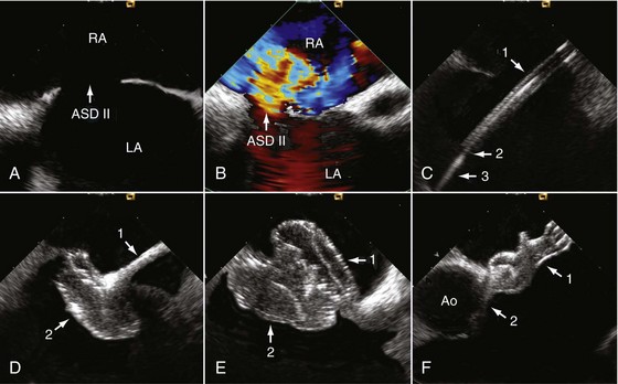
• While monitoring the opening of the right-sided counteroccluder, the delivery cable is carefully pushed forward until the counteroccluder also fits tightly into the atrial septum, but from the right side. Viewing two perpendicular cut planes (transatrial longitudinal and short-axis views) is mandatory to confirm the result and to rule out jamming of one of the counteroccluders in the interatrial communication (Fig. 6-5).
Several investigators demonstrated that ICE can safely guide interventional therapy in interatrial communications and that ICE monitoring is superior to conventional TEE.9–12 TEE requires general anesthesia with or without endotracheal intubation, whereas ICE permits unlimited echocardiographic viewing in fully conscious and compliant patients. This is of utmost importance, because malposition and migration of the device into the systemic or pulmonary circulation or perforation of the cardiac wall and rapid thrombus formation on the device are known to happen on occasion.7,13,14 ICE provides better image resolution than TEE and therefore facilitates the procedure, particularly when long continuous or repeated echocardiographic viewing is required or when complications begin to develop. ICE results in much less procedural stress to the patient, and fluoroscopic and procedural times can be shortened.9,12 Because many patients with interatrial communications are of reproductive age or younger, reduction of radiation exposure has to be considered a major advantage of ICE. In that respect, patients who undergo ASD closure benefit more from ICE than patients undergoing closure of a patent foramen ovale, because ASD closure is more complex and more time consuming. Employing ICE in the pediatric population is also recommended. Several years’ experience show that ICE is a practical and straightforward approach for guiding device closure in children and adolescents.2,11 The overall risk related to ICE appears to be low. Moreover, it is likely that ICE improves the safety of interventional device closure in interatrial communications. From an economic point of view, savings from shorter procedural time and from avoiding general anesthesia need to be weighed against the cost of the ICE catheter. After a brief learning curve, interventional cardiologists who are familiar with echocardiography can fully benefit from the advantages of ICE.
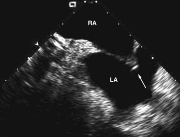
Monitoring of Percutaneous Left Atrial Appendage Closure
ICE guidance for LAA device closure has only been described in a few cases.15,16 It is an option in patients with atrial fibrillation in whom oral anticoagulation is contraindicated. Anatomical variation of the LAA, exclusion of thrombi, and the diameter of the ostium are usually assessed by TEE, which is also used for intraprocedural monitoring. As in any other percutaneous transseptal catheter interventions, one needs to establish access to the atrial appendage by septal puncture before LAA closure. This is best done under ICE guidance. Before atrial septal puncture, anatomic anomalies should be ruled out. When tenting of the fossa ovalis identifies contact with the transseptal needle, the pressure on the needle can be slightly increased until the needle perforates the atrial septum. For device closure, using novel placement of an intracardiac echo probe via a Mullins sheath in the RV outflow tract and pulmonary artery16 seems to be advantageous over viewing from the LA. This allows near-field visualization of device deployment in the LAA. This technique may increase the spectrum of patients who benefit from the procedure by decreasing procedure time, fluoroscopy, and procedure-related morbidity (Fig. 6-6).
Transseptal crossover and advancement of the dilator and sheath are adequately imaged and the ostium of the LAA is easily delineated and measured by ICE. Device positioning, release, potential periprosthetic leaks, and especially the spatial relation of the device to the surrounding structures can be continuously monitored in the transatrial longitudinal view. In some patients, the transventricular long-axis view can represent an alternative (see Table 6-3).
Guiding Radiofrequency Pulmonary Vein Ablation
The rapidly evolving field of interventional electrophysiology creates a demand for guidance by imaging. This is particularly true in view of the fact that currently available techniques, such as fluoroscopy and endocardial ECG, may be helpful but have certain limitations. In many cases, angiographic guidance of circular mapping catheters is not sufficiently accurate. After initial puncture of the interatrial septum, high-quality images provided by ICE are capable of guiding transseptal pulmonary vein ablation, a treatment option in atrial fibrillation. Delineation of the endocardium and direct visualization of the pulmonary venous ostium facilitate mapping and radiofrequency ablation by depicting the target area, ensuring electrode-tissue contact, and helping with energy titration (Fig. 6-7).
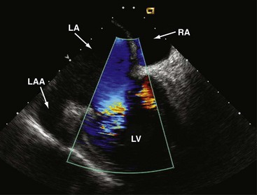
Figure 6-7 Transatrial longitudinal view.
Left atrial appendage (LAA) and transmitral flow into the LV.
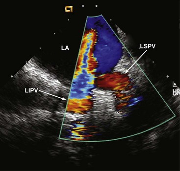
In the transatrial longitudinal view, the left pulmonary veins can be imaged by advancing the probe without tension or steering forces. Clockwise rotation of the catheter and insertion into the SVC allows the right pulmonary veins to be visualized in a cross-sectional view. Left or right steering permits longitudinal views of the right pulmonary veins. Thus, accurate anatomical positioning of the ablation catheter tip in relation to adjacent endocardial structures is supported17 (Fig. 6-8).
Doppler measurements of pulmonary vein flow velocities before and after ablation are recommended. During the procedure, the ablation zone can be directly visualized, including the evolving tissue injury. Visualization permits assessment of shape, cross-sectional area, wall thickness, and lesion formation18 and depicts lesion size and continuity.19 ICE is also useful for monitoring bubble formation during the phase of radiofrequency energy delivery, allowing radiofrequency dose titration to prevent overheating of the catheter tip. After effective ablation, transvenous flow velocities should be interrogated using continuous-wave Doppler in order to identify the potential presence of a gradient,20 which can occur as a complication. This illustrates that ICE contributes to the safety of the ablation procedure and to prevention or early detection of potential complications associated with electrophysiologic interventions, that is, thrombus formation21 and development of pulmonary vein stenosis.20 Periinterventional monitoring depicts each step of the ablation process, improves efficacy, and also reduces early and late complications.22 As demonstrated for device closure of interatrial communications, ICE can lower fluoroscopy time and shorten the ablation procedure.
Monitoring Transcatheter Aortic Valve Implantation
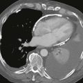
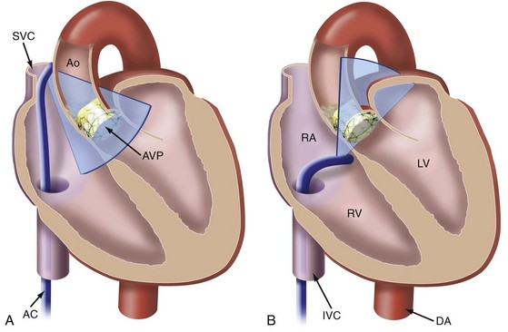
Generally, potential alternative sound windows are available for ICE-based intrainterventional assessment in TAVI. These include the transaortic window for viewing from inside the ascending aorta23 and the transventricular window for transseptal viewing from the right ventricle.24 Views from inside the aorta are inconvenient because the ICE catheter is prone to interfere with procedural catheters. In many individuals, it is also challenging to keep the ICE catheter stabilized in the RV (transventricular approach) throughout the procedure. However, longitudinal views from the lower SVC and the upper RA supplemented by RA short-axis views seem to be most suitable for continuous guidance, because the catheter position remains stable and the catheter does not interfere with the TAVI procedure24a (Figs. 6-9 and 6-10).
Even in asymptomatic patients, aortic stenosis is known to be associated with a poor prognosis.25 An increasing number of patients cannot undergo surgical aortic valve replacement owing to high perioperative risk due to comorbidities and advanced age.26 The periinterventional risk of TAVI must be weighed against these facts.27 Especially in extremely high-risk patients, each step of the procedure can cause life-threatening complications.28 Although periprocedural echocardiography is regarded as an important means of lowering the rate of complications, and although TEE monitoring is frequently used in those patients exposed to extreme risks to assist with the interventional steps and to detect complications, current guidelines for TAVI do not include any detailed methodologic suggestions for intraprocedural use of echocardiography.29
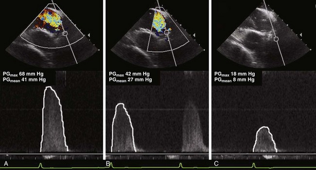
Echocardiography also qualifies as a tool for guiding TAVI with the purpose of increasing its benefit-to-risk ratio.30 Intraprocedural TEE has become an established method,29 although it is not necessarily an ideal guiding tool, one reason being the difficulty of aligning the Doppler beam with transvalvular flow in the deep transgastric view. Transgastric measurement of aortic valve blood flow cannot be considered a routine approach and is known to require a significant learning curve. It also may not depict the maximum transvalvular or transprosthetic gradient because the TEE approach results in a non-parallel Doppler angle. In contrast, the Doppler beam can be nicely aligned with transvalvular flow in the transcaval/transatrial longitudinal ICE view, and determination of transvalvular pressure gradients is therefore much easier than with TEE. The gradient not only gives an estimate of the effectiveness of predilatation, but helps to avoid unnecessary additional dilatations. This is meaningful for risk management because each balloon dilatation is associated with the risk of annulus dissection and significant aortic regurgitation.
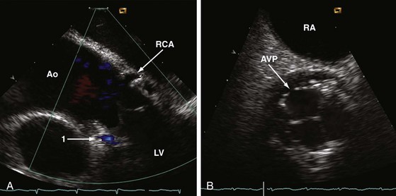
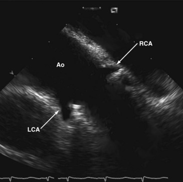
In contrast to TEE, the ICE catheter can be left in place with the probe aimed at the aortic valve during the entire TAVI procedure. Slight readjustments of the catheter may be occasionally required. Simultaneous and uninterrupted echocardiographic guidance by ICE is an ideal method for assisting predilatation, final adjustment, and deployment of the valve prosthesis; for ruling out potential complications as early as possible; for confirming proper prosthetic valve function without a need for repeated angiography; and for checking LV function immediately after implantation. Decreased use of contrast agents is meaningful, because renal failure has been reported to be the commonest short-term complication after TAVI.31 In comparison to TEE, ICE provides a more coaxial view of the ascending aorta and may therefore help to improve coaxiality between the valve-balloon system and the ascending aorta. ICE also assists wire crossing of the native valve in the majority of patients and better depicts the coronary ostia than TEE, which helps to rapidly exclude any obstruction by displaced debris from the calcified native valve (Fig. 6-11).
Both ICE and TEE approaches can be considered equivalent with respect to determining annulus size and LV function. Measuring annulus size is particularly critical and essential for selecting the correct size valve prosthesis. The ICE catheter is maneuverable by the interventional operator, who can adjust the transducer as needed and independently from a noninvasive cardiologist or anesthetist, while the ultrasound unit is operated by an ultrasonographic technician. Operated by an interventional cardiologist also experienced in echocardiography and especially in ICE application, this tool has some potential in minimizing procedural risks by avoiding and, whenever possible, detecting TAVI complications32 at the earliest possible time.
TAVI can also be completed under local anesthesia and moderate sedation,33,34 provided patients are selected accordingly. However, prolonged TEE imaging requires deeper sedation. The availability of ICE as an adjunct for TAVI lets the operator decide whether to use local anesthesia plus sedation or general anesthesia independently of the need for echocardiographic guidance.
Perioperative and Periinterventional Imaging of the Ascending Aorta
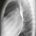
When a high transesophageal image plane—also known as “banana view”—is used, TEE depicts the caudal part of the ascending aorta anteriorly to the right pulmonary artery. Unfortunately, ascending aortic flow is not aligned with the Doppler beam in this plane. For that reason, perioperative functional assessment of the aortic valve and the ascending aorta by TEE is limited to regurgitant flow detection. Perioperative IPAI and ICE from the RA and the SVC may become alternative approaches for complete morphologic assessment of the ascending aorta and functional evaluation of the aortic valve. In order to display the proximal ascending aorta, the ICE catheter is used as described for TAVI. Alternatively, it can be inserted via a jugular venous access and advanced through the SVC into the upper RA. In contrast to transfemoral access, no fluoroscopic guidance is needed with the jugular venous approach because the access sheath guides the catheter sufficiently, making direct catheter navigation superfluous. From the superior RA, the aortic bulb and aortic valve can be displayed in the long-axis view and, after tilting the tip of the catheter, also in a short-axis view. After the catheter is pulled back into the SVC, a longitudinal cut plane of the whole ascending aorta reaching up to the innominate artery can be obtained. In contrast to TEE, systolic flow is mostly aligned with the Doppler beam of the catheter, permitting color flow and pressure gradient recordings of highest image quality. Therefore, ICE might be of clinical interest immediately after aortic valve surgery or surgery of the ascending aorta (Fig. 6-12).
Periinterventional Imaging of the Descending Thoracic Aorta
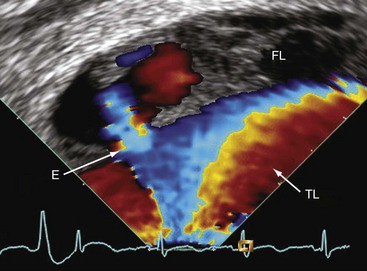
TEE adds incremental information, improving the safety of stent-graft placement in type B aortic dissection. In addition, IVUS is considered helpful in patients with complex dissection including abdominal extension.35 With respect to aortic diseases, the main limitation of IVUS is attributable to its inability to perform Doppler analysis. Flow detection by TEE is also limited if the flow is not aligned with the Doppler beam. In consequence, detecting flow from true to false lumen and vice versa by TEE depends on the alignment of the dissection flap. Therefore, TEE has a low sensitivity for detecting small entries and reentries (Fig. 6-13).
On the other hand, sonographic approaches may help lower the current complication rate of percutaneous stent-graft implantation,36 thus opening up new opportunities for monitoring interventional therapy in aortic diseases using IPAI. In that respect, IPAI not only combines advantages of TEE and IVUS, but adds capabilities.
The descending thoracic aorta cannot be viewed from any venous approach. Periinterventional sonographic diagnostic methods need to clarify which lumen supplies the side branches, a difficult feat with TEE and even with IVUS images. Thus, the need to navigate the aorta with the echocardiographic catheter turns from a disadvantage into an advantage, because the Doppler beam can be aligned with any flow between true and false lumen and with blood flow into small branches. Thus, intraaortic monitoring by IPAI has great potential to become a tool for the effective guidance of aortic stent-graft implantation, in such a manner that all entries are closed. First case reports also suggest that IPAI is capable of safely guiding other diagnostic intraaortic procedures in aortic diseases.37
Since the approval of the 8-Fr ICE catheter, its intraaortic use has added to the diagnostic spectrum in aortic disease.37 For intraaortic employment of the echocardiographic catheter, a very long access sheath is definitely recommended so that only the tip of the catheter with the transducer sticks out of the sheath. Sheath and indwelling catheter are then jointly pulled back while imaging is performed. The catheter can be rotated intermittently and aimed at the region of interest by tilting its tip.
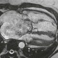
IPAI can also be used to safely guide percutaneous biopsies of intraaortic masses suspected to be tumors. To accomplish that, the transducer is aimed at the mass and the radial-jaw biopsy forceps (Fig. 6-14).
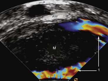
Figure 6-14 Intraluminal phased-array imaging of an intraaortic mass (M). 1, Flow around the mass; AW, aortic wall.
Under continuous ultrasonographic imaging, targeted biopsies are taken from the depth of the mass. Opening, pushing, and closure of the biopsy forceps can be precisely guided and documented.37 With careful handling, interference between the echocardiographic catheter and the lesion can be avoided. Nevertheless, there is some risk of peripheral embolization during the procedure.
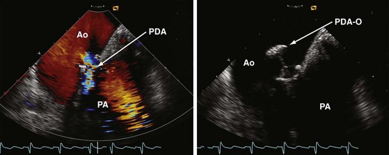
Percutaneous device closure of patent ductus arteriosus is another interventional approach nicely guidable by use of IPAI. It may help to reduce procedural time, limit radiation exposure, and lower the amount of contrast agent administered. It is conceivable that IPAI can contribute to the safety and success of this nonroutine procedure38 (Fig. 6-15).
Periinterventional Imaging of the Mitral Valve
Percutaneous transseptal balloon mitral valvotomy (BMV) (see Chapter 21) can be performed in concentric stenosis when the commissures are fused because of rheumatic heart disease without significant calcification and mitral regurgitation. Suitability of mitral stenosis for BMV can be assessed using the Wilkins score and a commissural score. As described for interventional left atrial appendage closure, atrial septal puncture is guided by the ICE transatrial longitudinal view. In that view, tool positioning in the LA can also be monitored. After introduction of a special guidewire into the LA, the transventricular long-axis view of the LV is obtained. Mitral ring diameter and intercommissural distance are measured, and the fused commissures are visualized. A balloon of appropriate size is selected. The same view is also useful for guiding a balloon through the stenotic mitral valve into the LV. Adhering to the double balloon technique, the distal balloon is inflated. Inflation should be monitored with ICE and fluoroscopy simultaneously. The next steps must be completed quickly to avoid prolonged LV inflow occlusion. Simultaneous echocardiographic and fluoroscopic viewing and documentation are recommended to accomplish this goal. The distal balloon is first inflated, and then pulled back toward the stenotic valve. Not until this step is completed is the proximal balloon inflated and valvotomy performed. At this time, ICE demonstrates that the balloon fits tightly into the stenotic valve orifice. The newer single-balloon technique39 may require even closer echocardiographic guidance to precisely position the cylindrical balloon into the stenosis.
After balloon deflation and withdrawal, immediate two-dimensional and Doppler analyses are recommended to show the split commissures and to exclude any injury of the commissures or the mitral valve apparatus. In addition, the degree of mitral regurgitation is reassessed. Intraprocedural ICE viewing may be considered an optional imaging modality, especially if the transthoracic acoustic window is very poor. It allows analysis of the valvular anatomy and is ideal when enhanced views are required.40 ICE is capable of providing excellent imaging and guidance, which results in low radiation exposure and minimizes the need for contrast angiography.15
Limitations
Finally, the relation between advantages and disadvantages of using ICE and IPAI depends mainly on the expenditure and the risk of the specific interventional procedures. Increasing familiarity of interventional cardiologists with this technique may also affect its use in clinical practice (Table 6-4).
TABLE 6-4 Usefulness and Effectiveness of Intracardiac and Intravascular Imaging
| Procedure | Clinical Benefit |
|---|---|
| Device closure of atrial septal defect | Very high |
| Device closure of patent foramen ovale | Moderate |
| Left atrial appendage closure | Moderate |
| Radiofrequency pulmonary vein ablation | Very high |
| PTSMA | Moderate |
| Transcatheter aortic valve implantation | High |
| Surgery of the ascending aorta | Undetermined |
| Interventional therapy of the descending aorta | Potentially high |
| Balloon mitral valvotomy | High |
| Surgical/interventional mitral valve repair | Undetermined |
PTSMA, Percutaneous transluminal septal myocardial ablation.
Key Points
| Interventional Procedure | Guidance by ICE |
|---|---|
| 1. Device closure of interatrial communications | View from the RA |
| 2. LAA occlusion | View from the RA (and RV) |
| 3. Radiofrequency pulmonary vein ablation | View from the RA |
| 4. Percutaneous transluminal septal myocardial ablation in hypertrophic cardiomyopathy | View from the RV |
| 5. Imaging of the ascending aorta and aortic valve | View from the SVC and RA |
| 6. Imaging of the descending thoracic aorta | Intraaortic view |
| 7. Imaging of the abdominal aorta | View from the IVC |
| 8. Mitral valve angioplasty and repair | View from the RA and RV |
1 Silvestry FE, Kerber RE, Brook MM, et al. Echocardiography-guided interventions. J Am Soc Echocardiogr. 2009;22:213-231.
2 Luxenberg DM, Silvestry FE, Herrmann HC, et al. Use of a new 8 French intracardiac echocardiographic catheter to guide device closure of atrial septal defects and patent foramen ovale in small children and adults: initial clinical experience. J Invasive Cardiol. 2005;17:540-545.
2a Zamorano JL, Badano LP, Bruce C, et al. EAE/ASE recommendations for the use of echocardiography in new transcatheter interventions for valvular heart disease. Eur Heart J. 2011;32:2189-2214.
3 Olgin JE, Kalman JM, Chin M, et al. Electrophysiological effects of long, linear atrial lesions placed under intracardiac ultrasound guidance. Circulation. 1997;96:2715-2721.
4 Bartel T, Müller L, Müller S. Intra-aortic phased-array imaging: new guiding tool for transcatheter aortic valve implantation. Eur Heart J. 2009;30:2368.
5 Hijazi ZM, Shivkumar K, Sahn DJ. Intracardiac echocardiography during interventional and electrophysiological cardiac catheterization. Circulation. 2009;119:587-596.
6 Bartel T, Müller S, Caspari G, Erbel R. Intracardiac and intraluminal echocardiography: indications and standard approaches. Ultrasound Med Biol. 2002;28:997-1003.
7 Chessa M, Carminati M, Butera G, et al. Early and late complications associated with transcatheter occlusion of secundum atrial septal defect. J Am Coll Cardiol. 2002;39:1061-1065.
8 Bartel T, Konorza T, Barbieri V, et al. Single-plane balloon sizing of atrial septal defects with intracardiac echocardiography: an advantageous alternative to fluoroscopy. J Am Soc Echocardiogr. 2008;21:737-740.
9 Bartel T, Konorza T, Arjumand J, et al. Intracardiac echocardiography is superior to conventional monitoring for guiding closure of interatrial communications. Circulation. 2003;107:795-797.
10 Mullen MJ, Dias BF, Walker F, et al. Intracardiac echocardiography guided device closure of atrial septal defects. J Am Coll Cardiol. 2003;41:285-292.
11 Koenig P, Cao QL, Heitschmidt M, et al. Role of intracardiac echocardiographic guidance in transcatheter closure of atrial septal defects and patent foramen ovale using the Amplatzer device. J Interv Cardiol. 2003;16:51-62.
12 Bartel T, Konorza T, Neudorf U, et al. Intracardiac echocardiography: an ideal guiding tool for device closure of interatrial communications. Eur J Echocardiogr. 2005;6:92-96.
13 Nkomo VT, Theuma P, Maniu VC, et al. Patent foramen ovale transcatheter closure device thrombosis. Mayo Clin Proc. 2001;76:1057-1061.
14 Martin F, Sánchez PL, Doherty E, et al. Percutaneous transcatheter closure of patent foramen ovale in patients with paradoxical embolism. Circulation. 2002;106:1121-1126.
15 Vaina S, Ligthart J, Vijayakumar M, et al. Intracardiac echocardiography during interventional procedures. Eurointervention. 2006;1:454-464.
16 Macdonald ST, Newton JD, Ormerod OJ. Intracardiac echocardiography off piste? Closure of the left atrial appendage using ICE and local anesthesia. Catheter Cardiovasc Interv. 2011;77:124-127.
17 Epstein LM, Mitchell MA, Smith TW, Haines DE. Comparative study of fluoroscopy and intracardiac echocardiographic guidance for the creation of linear atrial lesions. Circulation. 1998;98:1796-1801.
18 Tardif JC, Groeneveld PW, Wang PJ, et al. Intracardiac echocardiographic guidance during microwave catheter ablation. J Am Soc Echocardiogr. 1999;12:41-47.
19 Roithinger FX, Steiner PR, Goseki Y, et al. Low-power radiofrequency application and intracardiac echocardiography for creation of continuous left atrial linear lesions. J Cardiovasc Electrophysiol. 1999;10:680-691.
20 Callans DJ, Ren JF, Schwartzman D, et al. Narrowing of the superior vena cava-right atrium junction during radiofrequency catheter ablation for inappropriate sinus tachycardia: analysis with intracardiac echocardiography. J Am Coll Cardiol. 1999;33:1667-1670.
21 Ren JF, Marchlinski FE, Callans DJ. Left atrial thrombus associated with ablation for atrial fibrillation: identification with intracardiac echocardiography. J Am Coll Cardiol. 2004;43:1861-1867.
22 Marrouche NF, Martin DO, Wazni O, et al. Phased-array intracardiac echocardiography monitoring during pulmonary vein isolation in patients with atrial fibrillation: impact on outcome and complications. Circulation. 2003;107:2710-2716.
23 Bartel T, Müller L, Müller S. Intra-aortic phased-array imaging: new guiding tool for transcatheter aortic valve implantation. Eur Heart J. 2009;30:2368.
24 Vaina S, Ligthart J, Vijayakumar M, et al. Intracardiac echocardiography during interventional procedures. Eurointervention. 2006;1:454-464.
24a Bartel T, Bonaros N, Müller L, et al. Intracardiac echocardiography: a new guiding tool for transcathter aortic valve replacement. J Am Soc Echocardiogr. 24, 2011. 966–957
25 Rosenhek R, Zilberszac R, Schemper M, et al. Natural history of severe aortic stenosis. Circulation. 2010;121:151-156.
26 Iung B, Baron G, Butchart EG, et al. A prospective survey of patients with valvular heart disease in Europe: the Euro Heart Survey on Valvular Heart Disease. Eur Heart J. 2003;24:1231-1243.
27 Vahanian A, Otto CM. Risk stratification of patients with aortic stenosis. Eur Heart J. 2010;31:416-423.
28 Tuzcu EM, Kapadia SR, Svensson LG. “SOURCE” of enthusiasm for transcatheter aortic valve implantation. Circulation. 2010;122:8-10.
29 Vahanian A, Alfieri O, Al-Attar N, et al. Transcatheter valve implantation for patients with aortic stenosis: a position statement from the European Association of Cardio-thoracic Surgery (EACTS) and the European Society of Cardiology (ESC), in collaboration with the European Association of Percutaneous Cardiovascular Interventions (EAPCI). Eur Heart J. 2008;29:1462-1470.
30 Moss RR, Ivens E, Pasupati S, et al. Role of echocardiography in percutaneous aortic valve implantation. JACC Cardiovasc Imaging. 2008;1:25-28.
31 Dworakowski R, MacCarthy PA, Monaghan M, et al. Transcatheter aortic valve implantation for severe aortic stenosis—a new paradigm for multidisciplinary intervention: a prospective cohort study. Am Heart J. 2010;160:237-243.
32 Masson JB, Kovac J, Schuler G, Ye J, Cheung A, Kapadia S, et al. Transcatheter aortic valve implantation: review of the nature, management, and avoidance of procedural complications. JACC Cardiovasc Intervention. 2009;2:811-820.
33 Behan M, Haworth P, Hutchinson N, Trivedi U, Laborde JC, Hildick-Smith D. Percutaneous aortic valve implants under sedation: Our initial experience. Catheter Cardiovasc Interv. 2008;72:1012-1015.
34 Covello RD, Ruggeri L, Landoni G, Guarracino F, Bignami E, Gonfalini M, et al. Transcatheter implantation of an aortic valve: anesthesiological management. Minerva Anesthesiol. 2010;76:100-108.
35 Koschyk DH, Nienaber CA, Knap M, et al. How to guide stent-graft implantation in type B aortic dissection? Circulation. 2005;122(suppl I):I-260-I-264.
36 Eggebrecht H, Nienaber CA, Neuhäuser M, et al. Endovascular stent-graft placement in aortic dissection: a meta-analysis. Eur Heart J. 2006;27:489-498.
37 Bartel T, Eggebrecht H, Erbel R. Safe biopsy of aortic masses guided by intraluminal two-dimensional ultrasonography. Heart. 2004;90:974.
38 Bartel T, Gliech V, Müller S. Device closure of patent ductus arteriosus: optimal guidance by transaortic phased-array imaging. Eur J Echocardiogr. 2011;12:E9.
39 Joseph G, Chandy S, George P, et al. Evaluation of a simplified transseptal mitral valvuloplasty technique using over-the-wire single balloons and complementary femoral and jugular venous approaches in 1,407 consecutive patients. J Invasive Cardiol. 2005;17:132-138.
40 Salem MI, Makaryus AN, Kort S, et al. Intracardiac echocardiography using the AcuNav ultrasound catheter during percutaneous balloon mitral valvuloplasty. J Am Soc Echocardiogr. 2002;15:1533-1537.