23 Interventional Techniques for Device Implantation
Initially, device implantation was the province of surgeons, and thus implant problems were solved with surgical techniques, such as tunneling of a new lead for a patient with an occluded subclavian vein. As devices became smaller and almost exclusively transvenous, implantation moved to the province of the cardiologist and then subsequently to the electrophysiologist (EP). Until recently, the mechanics of transvenous device implantation were generally straightforward, adopting surgical solutions and applying an electrophysiology skill set and tools. Over the last several years, however, with the marked increase in device upgrades and cardiac resynchronization therapy (CRT), the complexity of device implantation has increased greatly, becoming similar to an interventional procedure rather than the traditional device implant. Lacking interventional training, EP physicians have struggled to solve difficult implant problems with their electrophysiology skill set and tools. As a result, even now, the CRT implant failure rate remains at least 7.5% in experienced hands.1
 Interventional versus Electrophysiologic Approach
Consider the occluded subclavian vein. With expanded indications for implantable cardioverter-defibrillators (ICDs),2 CRT,3,4 and increased survival of patients with cardiovascular disease,5 the implanting physician encounters a higher percentage of patients who have preexisting leads in whom subclavian vein obstruction or occlusion can be as high as 45%.6 Application of an interventional approach to the occluded vessel offers the implanting physician less invasive solutions, such as venoplasty versus lead extraction or tunneling.7–10
Left ventricular (LV) lead placement for CRT requires the successful completion of multiple steps, many originating in the interventional arena. Learning to implant an LV lead by application of an existing electrophysiology (EP) skill set and tools can be a long, painful, and humiliating process. Once learned, the EP approach has limited success, even in experienced hands. Because an interventional approach is better suited to the procedure, learning to implant an LV lead is usually faster, less painful, and more satisfying despite the requirement to first learn a new skill set and tools. Subsequently, application of the interventional approach can increase implant success from 88% to 92% with the EP approach to 98% with the interventional approach.11 This chapter takes the position that it is better to learn a new, unfamiliar skill set than to continue with the familiar that may not be best suited to the procedure (Box 23-1).
Box 23-1
Interventional Mind-Set Approach to Problems Encountered During Device Implantation
Morbidity and Mortality
Does the application of an interventional skill set specific to device implantation really reduce morbidity and mortality? Many examples show this may be the case, but the best example is sending a patient for an epicardial lead because the implanting physician does not use guide support or perform venoplasty. Even in the most experienced hands, mortality is doubled (4.8% surgical vs. 2.5% transvenous; P = 0.46), and acute renal injury and infection are quintupled (26.2% vs. 4.9%: P = .0004; and11.9% vs. 2.4%; P = .03, respectively).12 In practice, results may be worse. Surgical LV lead mortality from the REPLACE registry13 was greater than 8%. There were four deaths from among the 48 patients (11% of 434 attempted LV lead placements) who went for an epicardial lead following a failed transvenous approach. The 8% mortality assumes all 48 patients went to surgery, although it is not unusual for patients either to decline a surgical lead or to be rejected as too risky; thus the mortality may be even higher. Interventional techniques safely increase implant success, reducing the need for surgical epicardial leads.
Device Implantation–Specific Interventional Skill Set
We define a skill set as the combination of knowledge base and technical skills. Part of the interventional device implantation skill set involves basic interventional knowledge and technical skills unique to device implantation. A physician with formal interventional training in interventional cardiology or radiology may help provide the knowledge and technical skills necessary for device implantation. Because the terms, tools, and techniques used in the interventional approach to device implantation may be unfamiliar, a glossary box is provided for reference. See also the Interventional Implant Equipment List and manufacturers at the end of Chapter 22 and online.
Glossary and Definition of Terms
Training
Aggarwal and Darzi14 discuss how traditional EP and implanting physicians can become trained in the device implantation–specific interventional skill set. Their editorial “Technical skills training in the 21st century” addresses this issue as it relates to such areas as laparoscopic surgery, bronchoscopy, and colonoscopy. They describe proficiency-based training in which the environment can be modeled to simulate the experiences encountered and to generate feedback about both technical skills and knowledge base. Together, physicians who have adopted the interventional approach, device manufacturers, and professional societies can create a program to help the traditional EP physician develop the knowledge base and skill set specific to device implantation.
 Prevention of Contrast Nephropathy
Use of Contrast Material
The interventional mind-set approaches implant problems with the following attitude about contrast:
When considering the use of contrast for LV lead placement, keep in mind that a successful implant not only improves symptoms, but also reduces morbidity and mortality.15 Although uncommon in most situations,16,17 contrast nephropathy can be an important complication of CRT associated with increased morbidity and mortality and extended hospital stay.18 Patients with congestive heart failure and preexisting renal insufficiency are at increased risk for contrast nephropathy,19 but ultimately, CRT improves renal function by improving cardiac function.20 In fact, patients with moderate renal insufficiency may derive the greatest benefit from successful CRT.21
Recognizing the importance of contrast to a successful procedure, the interventional mind is proactive, always looking for ways to reduce risk,22 whereas the EP mind-set focuses on reducing the use of contrast. Despite every effort to limit its use, the volume of contrast frequently exceeds expectation. Further, the nephrotoxicity of even a small volume of contrast (10-30 mL) in the unprepared patient can be significant, whereas nephropathy can be reduced or eliminated if preventive steps are taken before the implant. Thus, it is important for implanting physicians to adopt the interventional mind-set and take a proactive approach to contrast nephropathy rather than simply trying to limit its use.
After exposure to contrast, the kidneys concentrate contrast in the urinary space within the renal tubules, releasing nitric oxide from endothelial cells, triggering a transient vasodilation, followed by more prolonged vasoconstriction, and causing tubular cell damage, extravasation into the peritubular space, and constriction of the lattice-like peritubular blood vessels in the outer medulla. Sustained vasoconstriction can last for hours to days, resulting in ischemic injury to the outer medulla, particularly in those with chronic kidney disease and diabetes mellitus23 (Box 23-2).
A bedside risk score stratifies patients into low (0-7 points), medium (8-14), and high-risk (≥15). The score is calculated as follows: age 80 or older (2 points), female (1.5), diabetes (3), urgent (PCI) (2.5), emergent PCI (3.5), congestive heart failure (4.5), serum creatinine of 1.3 to 1.9 mg/dL (5) or 2 mg/dL or greater (10), and pre-PCI use of intra-aortic balloon pump (13). Based on the score, high-risk patients can be identified for early administration of more aggressive and intensive prophylaxis.24,25
Periprocedural Hydration
Hydration Fluids
Hypotonic Saline
A 0.45 normal saline (NS) solution (in 5% glucose) should not be used; it is less effective than isotonic saline. In a study of 1383 patients, CIN was 2.0% with 0.45 NS versus 0.7% with isotonic saline.26
Isotonic Saline
Multiple clinical trials confirm that NS definitively reduces CIN. For example, Solomon et al.27 reported that with saline hydration, “There is little risk of clinically important nephrotoxicity attributable to contrast material (122 ± 90 mL) for patients (220) with diabetes and normal renal function or for nondiabetic patients with preexisting renal insufficiency. The risk for those with both diabetes and preexisting renal insufficiency is about 9%, which is lower than previously reported.” None of their patients required dialysis.
Sodium Bicarbonate
A 2004 study suggested that sodium bicarbonate was superior to saline hydration,28 although the hydration protocols were not the same. Subsequently, five published randomized clinical trials and three meta-analyses have provided conflicting results.29–31 Interpreting the data requires recognizing that in three of the six published studies (and several abstracts), the hydration protocol for saline and bicarbonate were not the same; thus the difference seen may reflect the effect of the infusion protocol rather than the infused solution. Only three published studies used the same infusion protocol.32–34 The smaller studies found bicarbonate superior to saline,33,34 whereas the larger study found no difference.32
Hydration Protocol
There is no direct comparison of overnight versus bolus infusion. However, analysis of the bicarbonate versus saline trials suggests bolus hydration is superior to overnight hydration, particularly in patients with congestive heart failure (CHF). When overnight saline was compared to bolus bicarbonate, saline was reduced for CHF patients in two studies35,36 (not defined by Merten et al.28). In the bicarbonate arm, the loading dose (3 mL/kg/hr for 1 hour) was not adjusted, but the infusion (1 mL/kg/hr during and 6 hours after procedure) was reduced to 0.5 mL/kg in one trial.32 Bicarbonate was superior to saline in the two studies where bicarbonate was not reduced, but equal to saline when the bicarbonate infusion was reduced for CHF.
Choice of Contrast Agent
Comparison of Contrast Agent Nephrotoxicity
Ionic vs. Nonionic
One randomized prospective evaluation of ionic diatrizoate (measured osmolality = 1500) vs. nonionic iopamidol (osmolality 796) found no difference in the incidence of nephrotoxicity.37 However the subsequent RECOVER study compared ionic, “low-osmolar” ioxaglate (osmolality 580) to nonionic, iso-osmolar iodixanol (osmolality 290) in patients with renal insufficiency undergoing coronary angiography with or without PCI.38 In addition to ionic versus nonionic, a second variable was “low osmolar” (580) versus iso-osmolar (291). The incidence of nephropathy was significantly lower with iso-osmolar nonionic iodixanol (7.9%) than with “low osmolar” ionic ioxaglate (17.0%) (P = .021). Unfortunately, some patients received hydration with 0.45 NS (ineffective; see earlier), and thus the difference may be caused by inadequate hydration. Further, the findings may also reflect the difference in osmolality.
Low-Osmolar Nonionic vs. Iso-Osmolar Nonionic
The NEPHRIC Study compared low-osmolar iohexol (osmolality = 884) with an iso-osmolar iodixanol (osmolality 290) and found nephropathy less likely to develop in high-risk patients with iso-osmolar iodixanol.39 Because NEPHRIC was small and hydration not uniform, and because several subsequent studies were flawed and produced conflicting results, the CARE trial was conducted to settle the issue. The Cardiac Angiography in Renally Impaired Patients study was a prospective, multicenter, randomized, double-blind comparison of the “low osmolar” nonionic iopamidol (osmolality 796) to the iso-osmolar nonionic iodixanol (osmolality 290) in high-risk patients.40 CIN, defined by multiple endpoints, was not statistically different in high-risk patients, with or without diabetes mellitus. All patients received prophylactic volume expansion with isotonic sodium bicarbonate solution, administered at 3 mL/kg/hr for 1 hour before angiography, and at 1 mL/kg/hr during and for 6 hours after angiography. Prophylactic N-acetylcysteine regimen of 1200 mg twice daily administered on the day before and on the day of the study procedure was used in some centers. The authors concluded that any true difference between the agents was small and unlikely to be clinically significant. Thus, if bolus hydration is used, either nonionic iso-osmolar iodixanol or nonionic low-osmolar iopamidol can be used. The conflicting results of NEPHRIC and CARE may reflect the approach to hydration.
Gadolinium
Although they may be less nephrotoxic than iodinated contrast agents, gadolinium-based contrast agents should never be used because of their association with nephrogenic systemic fibrosis, a relatively recently recognized,41 rapidly progressive fibrosing disorder of skin and internal organs. Nephrogenic systemic fibrosis is seen in patients with kidney disease (estimated glomerular filtration rate <30) who receive gadolinium-containing contrast agents.42
Carbon Dioxide
For more than five decades, gaseous CO2 has been recognized by interventionalists as an alternative to iodinated contrast for diagnostic as well as interventional procedures.43,44 Winters et al.45 recently described their favorable experience with gaseous CO2 venography rather than iodinated dye in patients undergoing pacemaker or ICD lead revisions.
Drugs to Prevent Renal Failure
N-Acetylcysteine
A potent antioxidant with vasodilator properties, N-acetylcysteine may prevent acute renal dysfunction by scavenging a variety of oxygen-derived free radicals and improving endothelium-dependent vasodilation. Several well-performed randomized clinical trials have demonstrated that the administration of acetylcysteine (Mucomyst) along with either saline or bicarbonate hydration prevented CIN in patients with chronic renal insufficiency.19,46,47 However, some still questioned the value of N-acetylcysteine, and two recent trials using high dose (1.2 grams twice a day for 48 hours) found no advantage over saline hydration alone in randomized trials of 250 STEMI patients48 and 2308 high-risk patients.48a Acetylcysteine should never be used as a substitute for hydration in CHF patients.
Ascorbic Acid
In a double-blind, randomized, placebo-controlled trial, the antioxidant ascorbic acid—administered as 3 g 2 or more hours before, 2 g the night after, and 2 g the morning after angiography or intervention—was demonstrated to reduce the risk of contrast-mediated renal dysfunction.49 However, a subsequent well-performed randomized study found no benefit.31
Iloprost
A prostacyclin analogue, iloprost works “presumably as a renal vasodilator and cellular protective agent downstream in the prostaglandin cascade to prevent contrast-induced acute kidney injury.”50 In a randomized, double-blind, placebo-controlled study of 208 patients with a serum creatinine of 1.4 mg/dL or greater, Spargias et al.51 reported CIN in 22% of controls and 8% of the iloprost group (1 ng/kg/min). All patients were hydrated with saline. Although dose-dependent hypotension and platelet inhibition are the principal side effects of iloprost, the incidence of hypotension and bleeding was not significantly different between groups.
Hemofiltration and Hemodialysis
In patients with a creatinine greater than 2 mg/dL, hemofiltration (4 hours before and continued for 24 hours after the procedure) compared to isotonic saline prevented the deterioration of renal function, decreased the need for renal replacement therapy, and improved in-hospital and long-term outcomes.52 Similarly, in patients with a creatinine more than 3.5 mg/dL, hemodialysis (a single, 4-hour treatment initiated immediately after procedure) reduced length of stay and the need for renal replacement therapy at hospital discharge.53
Treatments to Avoid
Fenoldopam (systemic IV administration), dopamine, calcium channel blockers, atrial natriuretic peptide, and l-arginine are not effective, whereas furosemide, mannitol, and endothelin receptor antagonists are potentially detrimental.54
Conclusion
Implanting physicians who are not accustomed to preimplant hydration are extremely concerned that CRT patients will suffer CHF decompensation. Thus they avoid hydration, increasing the risk of nephrotoxicity that can occur even when small volumes of contrast are used. Our experience with routine hydration for device implantation does not support the level of concern frequently expressed. Further, many CRT patients are hydrated for their interventional procedures (e.g., cardiac catheterization and PCI) without acute decompensation. Finally, there is the risk/benefit ratio of hydration to prevent CIN versus the possibility of exacerbating CHF. Contrast nephropathy results in an increased length of stay, higher morbidity, and both short-term and long-term mortality. Contrast nephrotoxicity is reduced if not eliminated by hydration. With the new, acute bolus approach to hydration, the total volume of IV hydration is lower, and the patient is under observation during the daytime hours. CHF may or may not develop as a result of hydration and can be treated if it does; thus hydration should be employed (Box 23-3).
 Preparations for Implantation
Room Setup and Table Position
The equipment required for the procedure needs to be on hand in the room, including the appropriate implant table (Fig. 23-1). The table and the assistant need to be in the appropriate position (Fig. 23-2). If the monitor is not in a comfortable position, mount a flat-screen monitor on an IV setup pole.
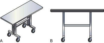
Figure 23-1 Implant table designed for cardiac resynchronization therapy.
(Courtesy Oscor, Palm Harbor, Fla.)
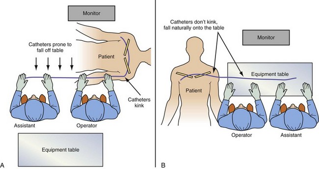
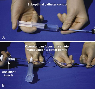
Catheter Manipulation and Contrast Injection
Electrophysiology physicians are used to working with electrode catheters that have almost infinite torque control and do not kink or twist as do open-lumen catheters. As a result, keeping the catheter straight before it enters the body and applying torque with both hands to distribute the force are not as essential as with open-lumen catheters. In addition, we become accustomed to working alone with our EP catheter, so when contrast needs to be injected, it is not the EP mind-set to do it alone. To work effectively with open-lumen catheters and inject contrast, the approach needs to change from an EP to interventional simply because the interventional approach to catheter manipulation and contrast injection is the way the tools were designed to be used (Fig. 23-3)
Balloon Basics
Type of Catheter for Balloon Mounting
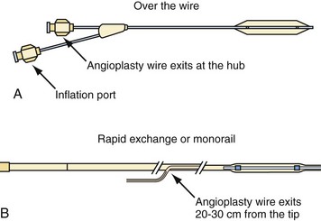
Balloon catheters are either “over the wire” (OTW) or rapid exchange (Fig. 23-4). The terms rapid exchange and monorail are synonymous. OTW coronary balloons are about 150 cm and thus require a 300-cm wire, which is very difficult to handle. We always use a rapid-exchange coronary balloon that requires a standard-length wire. Peripheral balloons are 40 to 60 cm; thus an OTW peripheral balloon uses a standard-length wire, which makes rapid-exchange models unnecessary. When balloons are made specifically for coronary venoplasty, they will be short enough to be OTW and still use standard-length wires.
Choice of Angioplasty Balloon and Inflation Pressure for Venoplasty
Compliance of Balloon
The term compliance refers to how a material deforms, or stretches, under pressure. This is an important consideration when selecting a balloon angioplasty catheter. Balloons of the same dimension will produce considerably greater force at the same pressure if the balloon material does not stretch. When a material stretches or deforms under pressure, it prevents the concentration of force from being focused at the stenosis. The balloon material stretches around the lesion rather than exerting force on it (Fig. 23-5, A) The more noncompliant the balloon material, the more dilating force it transmits, the more uniformly it expands, and the less risk it may pose of dilating healthy tissue (Fig. 23-5, B)
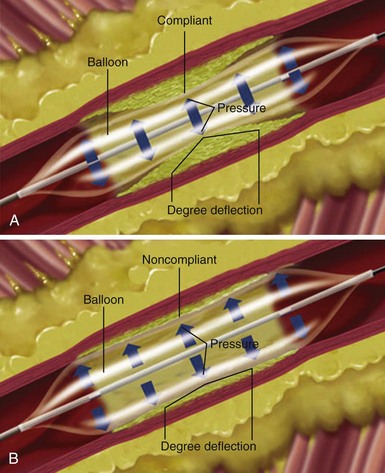
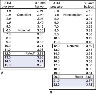
A more compliant balloon material exerts less dilation force at the lesion and increases the risk of “dog boning” and potential vessel dissections. Balloon dilation force is potentially applied outside the point of resistance or lesion. A less compliant balloon provides more dilation force within a vessel or metal stent, potentially reducing the risk of trauma outside the edges of the lesion. Figure 23-6 illustrates the impact of compliance on nominal pressure, rated burst pressure, and balloon size between nominal and rated burst pressure.
Profile of Balloon
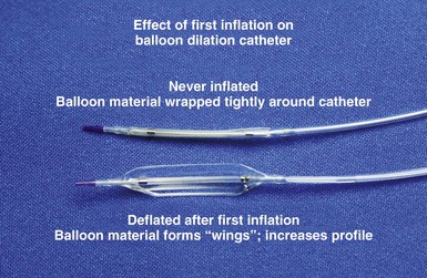
The outer diameter (OD) of the balloon in its wrapped, never-inflated state is referred to as the profile; the lower the profile, the easier it is to pass the balloon through the obstruction. Noncompliant balloons are made of thicker material; thus the OD of a 3-mm compliant balloon is less than OD of a noncompliant 3-mm balloon. Once a balloon is inflated, the profile is greater because of “winging” (Fig. 23-7). The balloon material is wrapped around the shaft, and once deflated, it remains unwrapped, increasing its profile.
Inflation Pressure
Box 23-4 summarizes major considerations in the preparation of a venoplasty balloon.
 Crossing Obstructed or Occluded Vein in Patients with Preexisting Leads
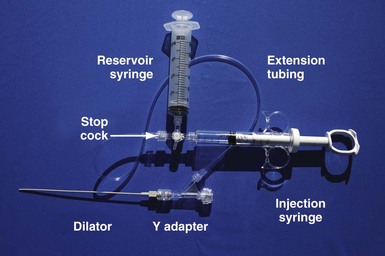
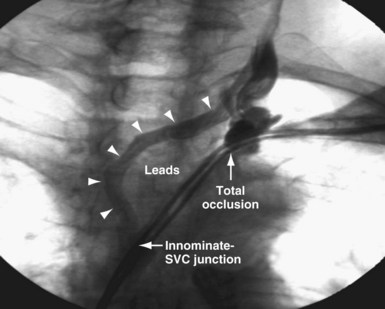
It is important to remember that “subclavian” is commonly used shorthand for the axillary/subclavian/innominate vein. Some degree of subclavian vein occlusion is common in patients with existing leads. The severity of the obstruction is often defined based on a venogram performed by contrast injection through an arm vein (peripheral venogram). When the peripheral venogram reveals an occlusion, it is best to enter the vein as far peripheral to the occlusion as possible to provide a stable access for approaching the occlusion (Fig. 23-8). A standard short J wire is then advanced to the occlusion and the needle exchanged for the dilator from a 5F sheath. The dilator is then connected to the Y adapter of the injection system (Fig. 23-9), and contrast is injected at the site of occlusion.
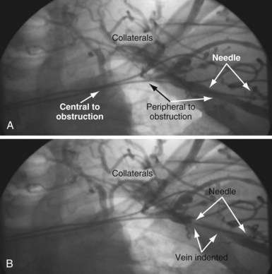
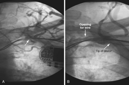
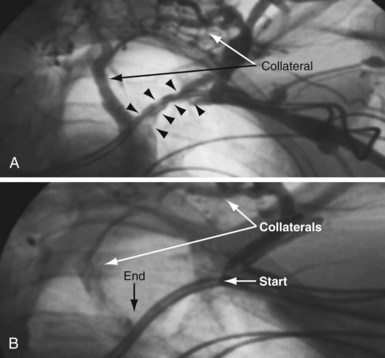
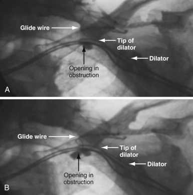
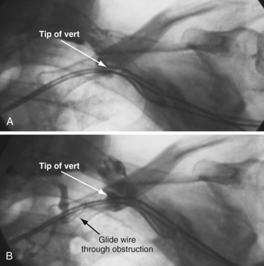
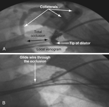
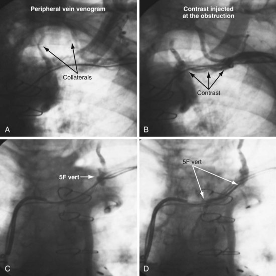
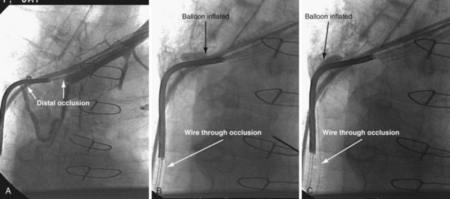
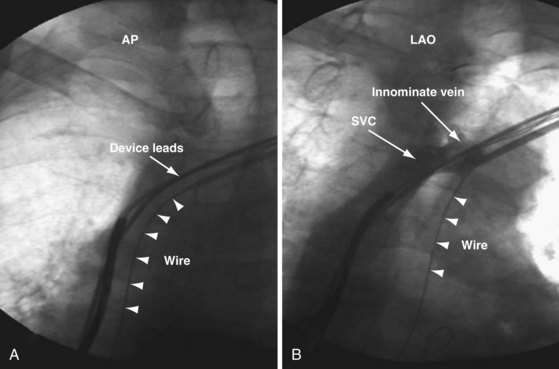
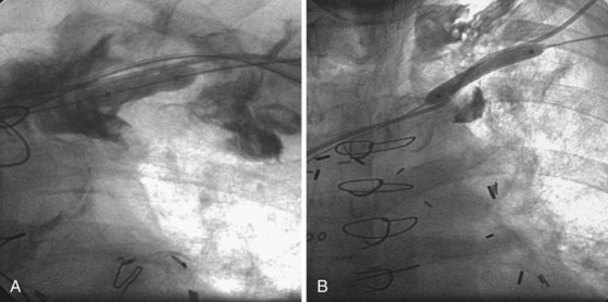
The length and severity of the occlusion may be either overestimated or underestimated by the peripheral venogram. In Figure 23-10 the peripheral venogram reveals extensive collaterals, and the occlusion appears complete in A, whereas in B, contrast injected at the site of occlusion demonstrates an opening that was easily crossed with an angled glide wire and torque device. In Figure 23-11, despite collaterals, the peripheral venogram in A suggests an opening that will be easy to cross, whereas in B, with injection of contrast at the occlusion, there is a total occlusion over 2 cm. Although it is important to perform contrast injection at the site of obstruction, the true, clinically relevant severity of obstruction is ultimately determined by whether a wire will cross the obstruction. For example, the venogram may demonstrate a hopelessly long, total occlusion, but the wire may cross easily (Fig. 23-12). Conversely, the stenosis may be short but impossible to cross with a wire. Accordingly, we define the obstruction based on how difficult it is to deliver a wire across the occlusion, as follows:
Crossing an Occluded “Subclavian” vein
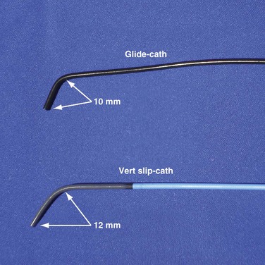
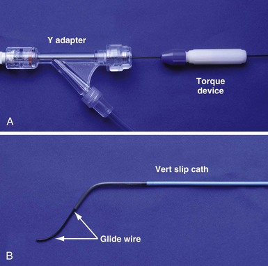
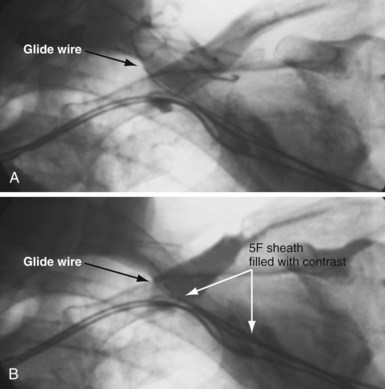
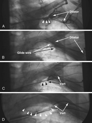
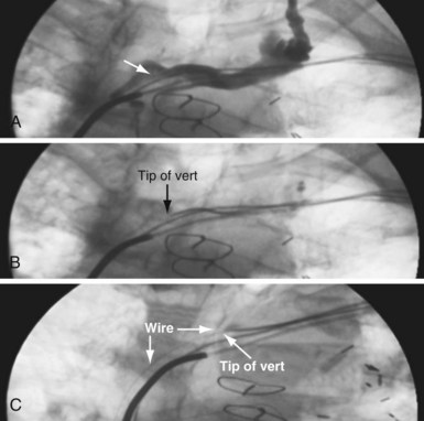
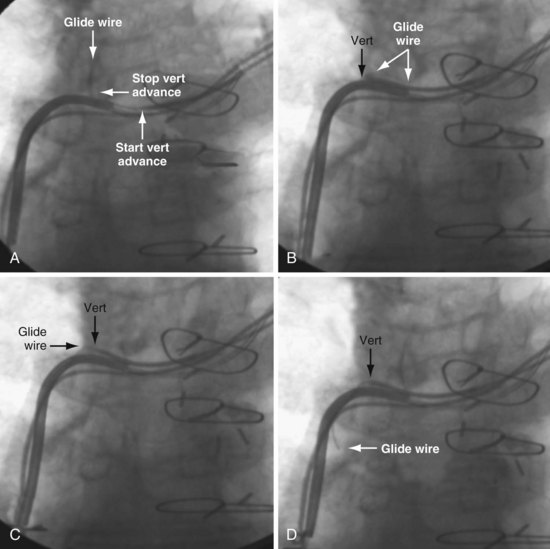
In some cases the axis of the dilator directs the wire away from the opening (Fig. 23-13; see also Fig. 23-18, A and B). Faced with this situation, we have evaluated a variety of catheters and catheter shapes and found a hydrophilic, left vertebral diagnostic catheter (vert slip-cath, vert) (Fig. 23-14), in conjunction with a torque device and angled glide wire (Fig. 23-15), to be most useful. The short tip of the “vert” can be turned in the vein peripheral to the occlusion, directing the glide wire toward the opening (Fig. 23-16). The hydrophilic coating on the catheter is important to ensure the catheter will advance as the glide wire is advanced; however, it can slip through the operator’s fingers and out of the vein. To avoid loss of venous access while using the vert, it is useful to exchange the dilator of the 5F sheath for the 5F sheath (Fig. 23-17). The sheath is more secure in the vein than the vert, even if only a few millimeters are in the vein. Once in place, the vert is connected to Y adapter of the injection system and advanced to the occlusion with puffs of contrast. Once at the occlusion, the vert is turned in the direction of the opening and the glide wire advanced; the vert is useful for peripheral occlusions (Fig. 23-18) as well as central occlusions (Fig. 23-19). The support and direction of the vert can also be used to direct the wire through what appears to be a total occlusion (Fig. 23-20). In addition, the vert can be advanced without a guidewire using contrast and orthogonal views to confirm position (Fig 23-21). Figure 23-22 illustrates the synergism of the glide wire and the left vertebral catheter.
Total Occlusion: Unable to Manipulate Wire
In most cases, a wire can be manipulated across the obstruction and venoplasty safely performed.3 However, some are wire refractory. Most of the approaches to a wire-refractory total occlusion have limitations. A very proximal subclavian stick increases the risk of hemothorax, pneumothorax, and, if successful, the risk of clavicular crush. The supraclavicular approach carries the risk of insulation damage or lead fracture from contact with the clavicle.55 Tunneling requires a second incision (with associated risk of infection) and sacrifice of the other subclavian vein.56 In addition, the tunneled lead is prone to erosion and fracture. When a wire cannot be advanced across the occlusion, there are two options: sacrificing one of the leads or using specialized crossing tools (microdissection, laser wire, radiofrequency guidewire).
Establishing Venous Access By Sacrificing an Existing Lead
Prepectoral Sheath Extraction (Powered or Mechanical)
Gula et al.57 report that “central venous occlusion is not an obstacle to device upgrade with the assistance of laser extraction.” Although extraction of a functional lead can be performed safely in some centers by experienced operators, it still carries a small risk of serious complications (including death), loss of the functional lead, and dislodgement of adjacent lead(s) tethered to the lead being extracted. In addition, the lead may be extracted without regaining venous access. When the lead dislodges prematurely during prepectoral sheath extraction, the lead can be snared and held in the circulation while the sheath is forced through the fibrous tissue over the lead. However, it might be easier and safer to cut off the connector, insert a wire in the lumen, and extract the lead using the femoral approach, followed by venoplasty (see later). If the lead is not functional, extraction is a more appealing option, but careful assessment of the risk/benefit of the extraction procedure and the experience of the operator must be considered.58 Before the development of the techniques described later, extraction was the only option for implantation of a new lead (see Chapter 26).
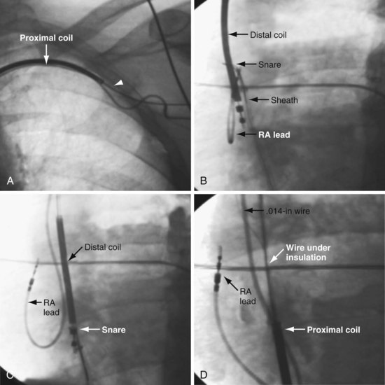
Prepectoral Wire under Insulation Technique Followed by Venoplasty
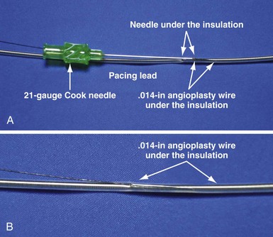
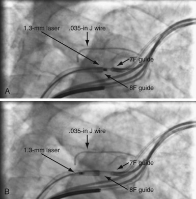
The lead to be sacrificed is partially extracted and a wire inserted under the insulation (Figs. 23-23 and 23-24). Using a stiff stylet, the lead is advanced back into the circulation, carrying along the wire. The wire and lead are separated by advancing the lead and fixing the wire. The lead is then extracted, retaining the wire. The ability to readvance the lead into the circulation with a stiff stylet depends on (1) implant duration, which determines the extent of fibrous tissue encasing the lead; (2) size of the wire under the insulation; and (3) lubricity of the wire under the insulation. This method is usually reserved for leads in place less than 1 month but can be successful up to 2 years if a hydrophilic .014-inch angioplasty wire is placed under the insulation. Once the .014-inch angioplasty wire is free in the circulation, it is exchanged for a .035-inch extra-stiff J wire using a 4F to 5F hydrophilic catheter. When used for leads implanted for more than 1 month, venoplasty is usually required because of the fibrous sheath that develops around the lead. When the lead cannot be advanced back into the circulation, femoral extraction can be used.
Establishing Venous Access with Specialized Tools Using Leads for Direction
Various mechanical devices have been utilized to cross wire-refractory total occlusions, including a flexible hollow tube with screwlike surface contour (Tornus), microdissection, and laser. We evaluated the Tornus, but after our first case, had very limited success.59
Microdissection
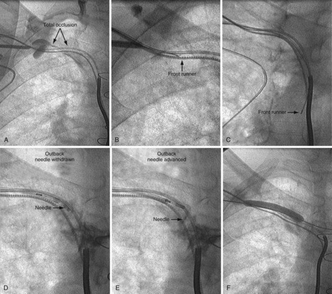
The Frontrunner XP CTO Catheter (Cordis Endovascular, Miami) is a device designed for microdissection through total occlusions in interventional radiology (Fig. 23-25). For short, total venous occlusions, the Frontrunner is often very successful60,61 (Fig. 23-26), but in some cases the jaws will not engage the occlusion. Microdissection is a slow process; thus, although it is possible to open long, total occlusions, it requires a long procedure (Fig. 23-27). In addition to being a slow process, microdissection can result in the jaws of the device stuck in the fibrous tissue surrounding the lead beyond the total occlusion, unable to reenter the true lumen (Fig. 23-28). This is addressed with a directed needle reentry catheter62 (OutBack LTD Re-Entry Catheter, Cordis), a companion device of the Frontrunner (Fig. 23-29). The OutBack is an open-lumen catheter with a curved, extendable, retractable 21-gauge needle on the distal end. The OutBack with needle retracted is advanced through the channel created by the Frontrunner catheter, until the tip is in the fibrous tissue outside the distal true lumen. The needle is advanced with the tip angled toward the true lumen. A .014-inch guidewire is then advanced into the distal true lumen, the OutBack catheter is withdrawn over the wire, and venoplasty is performed.
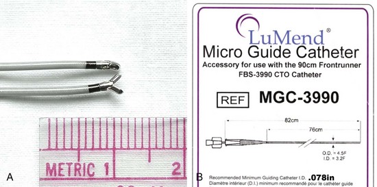
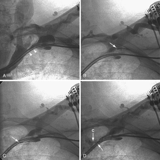
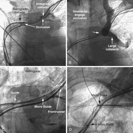
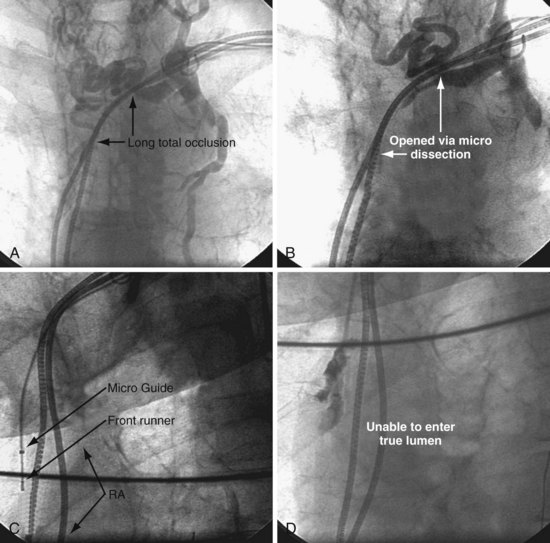
Figure 23-28 Failure of microdissection catheter to enter true lumen despite successful microdissection beyond the occlusion.
Radiofrequency Guidewire
Several groups report successful recanalization of a long-standing, complete left subclavian vein occlusion by radiofrequency (RF) perforation with use of an RF guidewire in dialysis patients, some of whom have had a pacemaker on the same side.62,63 Radiofrequency is also used as an alternative to needle puncture in cases of complete superior vena cava (SVC) occlusion after Mustard repair.64 Based on this experience, radiofrequency could be used to regain central venous access by adding a lead to an existing device. Although possible, it seems unlikely that the RF energy would be sufficient to damage the adjacent leads. As with microdissection, however, the RF wire does not have a central lumen; thus, to determine if it has reached the true lumen, a guide catheter must be advanced and RF wire removed. It is more comforting to have a device with a central lumen, where a wire can be advanced to confirm arrival in the central lumen.
Direct Needle Puncture
Honnef et al.65 report using a transjugular intrahepatic portosystemic shunt set (TIPS needle) followed by venoplasty and stent to recanalize the chronically occluded left brachiocephalic of a hemodialysis patient. Sadarmin et al.66 implanted an ICD despite chronic total occlusion of the SVC by directing a 21F Colapinto needle (Cook Medical) from the right internal jugular vein through the occlusion, followed by venoplasty and stent. The report was followed by an editor’s warning that insertion of a needle into a total occlusion is fraught with failure or complication, even with fluoroscopy. Concerns include perforating the vessel, then possibly reentering the true lumen distal to the occlusion.
Laser Crossing of Total Occlusions
The open-lumen excimer laser can be used to cross total occlusions in the arterial system.67 The laser directs high-energy photons to cause molecular bond disruption at the cellular level (photoablation) without thermal damage to the surrounding tissue. The excimer laser transmits ultraviolet energy from the source (CVX-300TM Excimer Laser System, Spectranetics, Colorado Springs) to photoablate fibrous, calcific, and atheromatous material. Laser photons cause vaporization of contrast; thus residual contrast must be flushed from all catheters, the lasing site, and vascular structures adjacent to the lasing site prior to lasing. Laser catheters are indicated for treatment of both lower-extremity and coronary arteries when a total obstruction cannot be crossed with standard guidewires.16 The risk of perforation is greatest when the diameter of the laser catheter is close to the diameter of the vessel. In the subclavian, the 0.9-mm diameter laser is far smaller than the vessel. The laser must be advanced at less than 1 mm per second to allow time for the high-energy photons to disrupt the molecular bonds at the cellular level without thermal damage to the surrounding tissue.
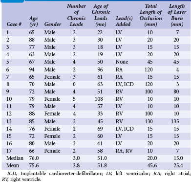
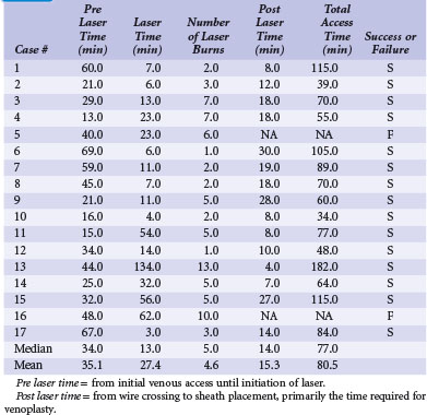
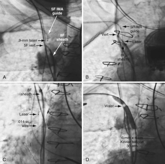
Our experience with the laser began when microdissection failed,68 but the laser was successful in crossing the total occlusion (Fig. 23-30). Subsequently, we have used the laser successfully,69 now in 15 of 17 consecutive cases; 16 on the left and one right. The acute angle where the right innominate enters the SVC could make it more difficult; however, we used a 5F internal mammary artery (IMA) guide to successfully direct the laser. The clinical characteristics for our patients are shown in Tables 23-1. Sixteen of the 17 had existing leads; one patient presented with an infected system on the right and an occlusion on the left related to leads extracted 27 months previously for an infected system. Most of the upgrades were for an LV lead. Fifteen of the 17 cases were successful. The two unsuccessful laser-crossing cases both had long total occlusion where the lumen distal to the occlusion was stenotic, making it difficult to define as a target for the laser. There were no clinical complications, although contrast stains were observed in 11 of 17 patients. In six patients the stains were mild (<1 cm in diameter), in four moderate (1-2 cm), and one extensive (3.5 cm). Tables 23-1 and 23-2 present clinical and procedural details of the laser-crossing cases.
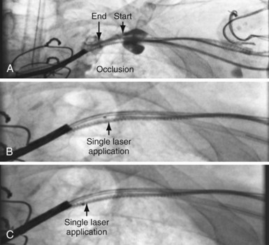
Figure 23-30 Peripheral and central extent of 10-mm occlusion well defined, and single application of laser energy successful.
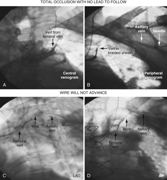
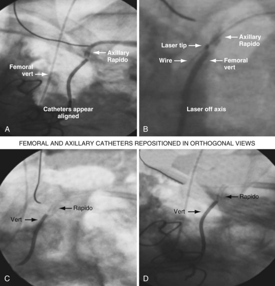
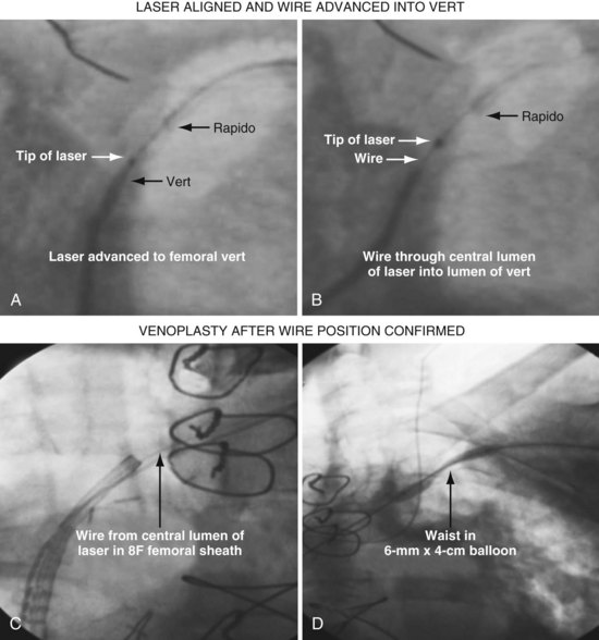
As illustrated in Figure 23-30, when the peripheral and central extent of the occlusion is well defined by antegrade contrast injection and the occlusion is less than 10 mm, crossing the occlusion may require only a few applications of laser energy. However, peripheral contrast injection even at the site of occlusion may not define the central extent of the occlusion as well as it first appears (Fig. 23-31, A). When the laser did not reach the lumen central to the occlusion after four applications of energy, a femoral catheter was advanced to define this lumen (Fig. 23-31, B). In cases with known long total occlusions we start with both femoral and pectoral access (Fig. 23-32). The precise direction of the laser may not be apparent from the anteroposterior (AP) projection (Fig. 23-33). Thus, the tip position is always confirmed in orthogonal views before lasing. Depending on the length of the occlusion and position of the laser tip, forward lasing may be continued, or the laser withdrawn and redirected with the guide. Long total occlusions can be time-consuming and require multiple applications of laser energy. Before each subsequent application of laser energy, the tip is positioned firmly against the occlusion and its position confirmed in orthogonal views. When the lumen central to the occlusion is not well defined, it may be necessary to place a guide from the femoral in the central lumen and direct the laser into the lumen of the femoral guide (Fig. 23-34). When resistance decreases or the tip appears to be in the vein or guide central to the occlusion, the preloaded 300-cm, .014-inch angioplasty wire is advanced into the pulmonary artery (PA) or inferior vena cava (IVC) and venoplasty performed.7 If the wire does not advance freely to the PA, it must be assumed that the laser is not in the lumen; it is withdrawn and redirected with the guide.
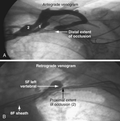
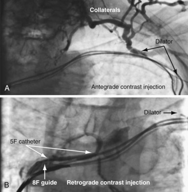
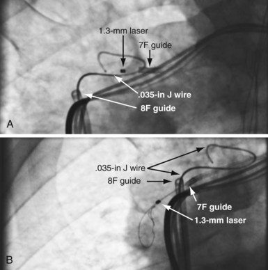
Figure 23-33 Demonstration of importance of orthogonal views for laser crossing of total occlusions.
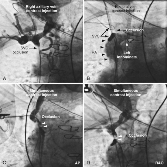
Figures 23-35 and 23-36 illustrate a right-sided implant with total occlusion of the SVC above the left innominate vein. The patient has an arteriovenous fistula for dialysis in the left arm. The existing leads were implanted 5 years previously via the internal jugular and tunneled to the left side after extraction of an infected system on the right. Although the failed right ventricular lead could have been extracted for access, the lead would need to be tunneled from the right internal jugular to the left side over the clavicle and across the sternum, resulting in the same stress factors that caused the lead to fail initially. One patient with a chronic total occlusion without leads to follow required a laser to cross the obstruction (see Figs. 23-39 to 23-41). This case is discussed in detail in the section on total occlusions without implanted leads to follow or extract.
Limitations of Current Equipment and Procedure for Laser Crossing of Wire-Refractory Total Occlusions
Total Occlusions in Patients Without Implanted Leads
Access to the central vasculature can be regained using interventional techniques. However, most EP physicians send patients with bilaterally occluded subclavian/innominate vein for an epicardial or a femoral system. A variety of occlusions can be successfully opened, although the success rate is lower than in patients with retained pacing or defibrillation leads. The occlusion may be short (Fig. 23-37) or long (Fig. 23-38). There may be flush occlusion at the innominate-SVC junction (see Fig. 23-38), or the innominate may be patent and well reconstituted central to the occlusion (see Fig. 23-37). It may be possible to cross the obstruction with a wire, or it may require a laser (Figs. 23-39 to 23-41).
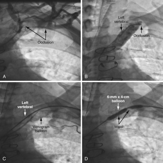
Figure 23-37 Venous access despite total subclavian occlusion without pacing leads to provide direction.
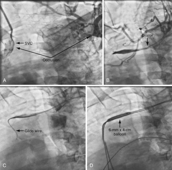
Figure 23-38 Venous access despite long total subclavian occlusion without pacing leads to provide direction.
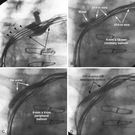
When approaching a case with known occlusion and no leads to follow we start by evaluating the central extent of the occlusion. First, a long, 8F braided sheath (Preface Guiding Sheath, Cordis) is advanced to provide a stable supportive platform in the SVC. A 5F left vertebral diagnostic catheter is then advanced into the SVC and puffs of contrast used to locate the innominate (Fig. 23-37, B). To make the central extent of the occlusion easier to visualize for the prepectoral approach to the occlusion, a venogram balloon is inflated (see Fig. 23-37, C). Moving from the femoral to the prepectoral area, venous access is obtained in the axillary vein peripheral to the occlusion, and a 5F sheath inserted. Using the venogram as a target, the obstruction is crossed with a glide wire and a 5F left vertebral catheter (see Fig. 23-37, C). Venoplasty is performed once the wire is across the occlusion and position is confirmed in orthogonal views (Fig. 23-37, D). Figure 23-38 is an example of a long total occlusion without wires to follow where there is flush occlusion of the innominate as it enters the SVC. When it is not possible to cross into the innominate vein central to the occlusion with a wire, a laser can be used to bridge the gap. See Figures 23-39 to 23-41 for details of the procedure. Box 23-4 lists venoplasty equipment. Box 23-5 lists the equipment required for crossing an obstructed axillary/subclavian vein and performing venoplasty. Subclavian venoplasty is covered in the next section.
Box 23-5
Equipment for Crossing and Dilating Stenotic/Occluded Subclavian Veins
See Interventional Equipment List at the end of Chapter 22 and online for details and ordering information.
John Gurley and the group from the Gill Heart Institute at the University of Kentucky described inside-out central venous access (IOCVA) in eight patients.69a IOCVA is an important, well-reasoned new approach for central venous access that can be applied to patients with chronic total SVC and subclavian vein occlusions that cannot be recanalized with currently available technology. IOCVA is a new concept that reverses the approach by directing a needle outward from within the body. The authors reasoned that IOCVA can be performed safely because there are consistent anatomic relationships adjacent to the thoracic central veins. The central veins are bounded anteriorly by the clavicle, soft tissues, and skin. A needle directed anteriorly will not encounter arteries, nerves, or pleura, which lie posterior and lateral to the central veins. IOCVA allows the placement of conventional leads and devices in optimum locations.
 Subclavian Venoplasty: Response to Stenosis between Axillary Vein and Right Atrium
Venoplasty vs. Progressively Larger Dilators
Drawbacks to Progressively Larger Dilators
Increased Risk of Complications with dilators
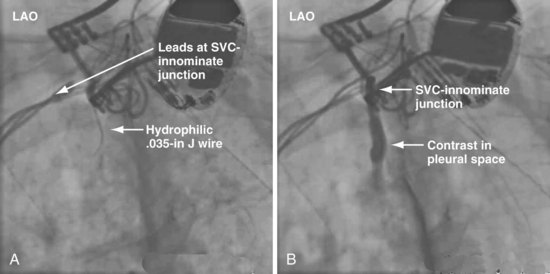
Figures 23-42 and 23-43 illustrate a catastrophic vascular event during the use of progressively larger dilators. It is important to note the glide wire did not perforate the dilator but simply exited through a branch feeding the innominate vein. The branch vein is a thin-walled structure not encased in fibrous tissue; thus, advancing the dilator lacerated the vein. Wire position in the AP projection can be deceptive. To be certain the wire has not exited the vein, progressively larger dilators (and balloons) should never be advanced until the wire is in the PA or IVC and confirmed to be adjacent to the leads in orthogonal views.
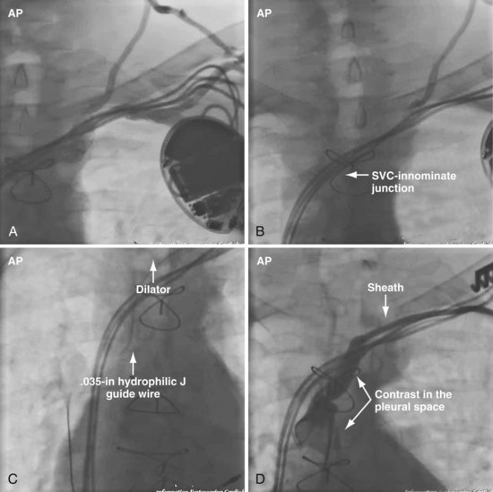
Figure 23-42 Hemodynamic collapse during use of progressively larger dilators to open subclavian occlusion.
Performing Subclavian/Innominate Venoplasty
As previously discussed, it is important to define clearly the situation with contrast injection at the site of occlusion (Fig. 23-44). Before starting venoplasty, the implanting physician must consider which wire is across the occlusion and what level of support is required to advance the balloon beyond the obstruction. The .035-inch glide wire that is most frequently used does not provide optimal support. Thus, upsizing to a .035-inch extra-stiff wire using a 4F to 5F hydrophilic catheter is a worthwhile first step rather than first trying to advance the balloon.
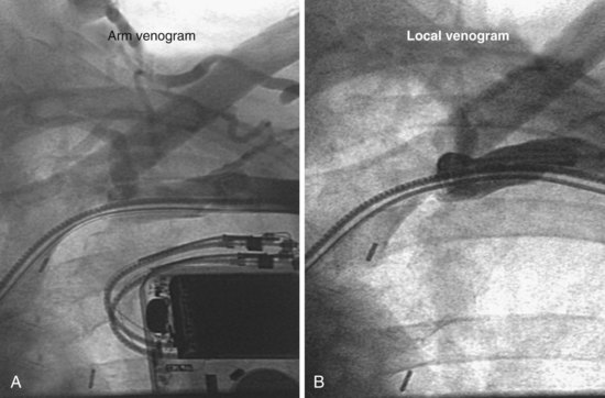
Figure 23-44 Arm and local venograms of a typical high-grade stenosis at axillary-subclavian junction.
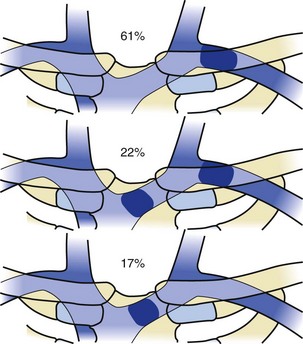
In patients with previously implanted leads, venoplasty may be required anywhere between the right atrium and the axillary vein (Fig. 23-45). The most common site of obstruction is in the area of the clavicle (Fig. 23-46). A central occlusion is encountered in approximately 30% of patients with a peripheral occlusion. An isolated central occlusion accounts for approximately 10% of venoplasties. The lumen of the balloon must be large enough to accommodate the wire across the stenotic area, usually a .035-inch angled glide wire (Terumo Medical, Somerset, NJ). In addition, the inflated diameter of the balloon must be large enough for the 9F sheath (9F ID/11F OD) to pass freely after dilation (6 mm). Lastly, the balloon must be long enough to dilate from the right atrium to the axillary vein with three to five inflations (4 cm).
Initially, the balloon is inflated to the “nominal pressure” (listed on the package). At the nominal pressure, the balloon reaches the labeled diameter. The pressure is then increased until the “waist” opens or the balloon bursts. A balloon typically used by interventional radiologists is the PowerFlex P3, which is 6 mm × 4 cm with a .038-inch lumen (Cordis, Miami). If the stenosis does not submit to the initial balloon, an ultra-noncompliant (aramid fiber [Kevlar]), high-pressure balloon may be used (Conquest PTA Dilatation Catheter [Bard Peripheral Vascular, Tempe, Ariz.] or equivalent). Once the proximal stenosis is dilated, the balloon is advanced to the RA-SVC junction and inflated to nominal pressures from the right atrium back to the axillary vein in an overlapping manner. In this way, any occult distal stenotic areas are revealed and opened (Fig. 23-47).
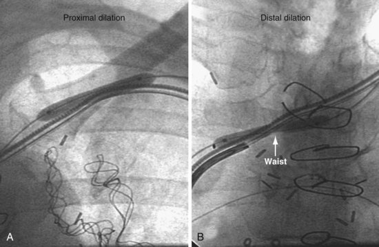
Figure 23-47 Dilation of both proximal (peripheral) and distal (central) subtotal venous occlusions encountered in same patient.
Balloons for Subclavian Vein Venoplasty
Why not use coronary balloons for subclavian venoplasty? We switched from coronary balloons to peripheral balloons for several reasons, including the diameter of the wire across the stenosis. When dealing with stenotic subclavian veins, we usually start with a .035-inch angled-tip glide wire. Coronary balloons track over wires .014 inch or less; thus, to use a coronary balloon, the wire must be downsized to .014 inch, where many peripheral balloons are designed to track over wires .038 inch or less. In addition, coronary balloons are less than 21 mm in length. The number of head-to-tail inflations required for the 21-mm balloon (Fig. 23-48, A) to cover the vein from the SVC-innominate junction to the pocket is prohibitive compared to the 40-mm peripheral balloon (Fig. 23-48, B). Finally the diameter of most coronary balloons is less than 4 mm, which is too small for passing a 9F sheath. Although we do not know the optimal size of balloon, we started with a peripheral balloon 6 mm × 4 cm in diameter and have not found the need to change after experience with more than 300 cases.
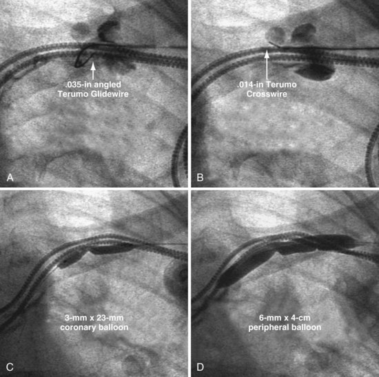
A coronary balloon may be necessary to predilate the lesion when the only wire to cross the occlusion is .014-inch or .018-inch angioplasty wire (Fig. 23-49). The Hi-Torque Cross-It 300XT (Guidant, Boston Scientific, Natick, Mass.) and the .014-inch Crosswire (Terumo Medical), among others, are specifically designed to cross total coronary occlusions. They may be used to cross a subclavian occlusion when the .035-inch wire will not advance. When the only wire that will cross the lesion is a .014-inch, we start with a 2- to 3-mm coronary balloon. Once the stenosis is dilated with the coronary balloon, our usual .038-inch lumen peripheral balloon may track over the .014- or .018-inch wire.
In summary, coronary balloons are too short, their diameters too small, and their lumens too narrow for the typical .035-inch access wire. Coronary balloons are used when a .014-inch wire is all that will cross the occlusion. As soon as the stenosis is partially dilated, the .014 wire is usually replaced with a .035 wire (see Fig. 23-49). Recent availability of .018-inch lumen peripheral balloons provides more options.
Short Balloons for Central Stenosis (Superior Vena Cava–Innominate Vein Junction)
As previously noted and shown in Figure 23-47, many patients with a peripheral stenosis also have a central stenosis. In these cases, progressive dilation of the proximal occlusion leaves the distal stenosis untouched, further restricting lead manipulation. In some patients, only a distal occlusion is encountered. Initially, we used short balloons (<20 mm) for the SVC-innominate junction occlusion (Fig. 23-50), thinking there was too sharp an angle to accommodate a longer balloon. However, on further reflection we realized that the wire is not constrained with the lead but enters the SVC; thus the central end of the balloon is free and is not forced to follow the bend of the leads. Figure 23-50 shows a distal-only occlusion that appears to be on a sharp bend, dilated with a short balloon at multiple sites.
Kevlar Balloons and Focused-Force Venoplasty
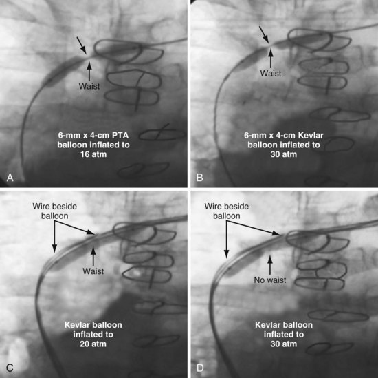
In some patients, the stenosis is particularly resistant to dilation, requiring special balloons. In Figure 23-51, an angled .035-inch angled glide wire was manipulated across the stenosis, but the sheath would not advance. The stenosis was dilated with a 6 mm × 4 cm balloon delivered over the glide wire. Figure 23-51, A, demonstrates the balloon dilated at 16 atmospheres (atm); at 20 atm, the balloon ruptured without eliminating the stenosis. A Kevlar balloon (Conquest) was then advanced across the occlusion (Fig. 23-51, B). Once the second balloon was inflated to 22 atm, the stenosis was relieved, and the 9F sheath (9F ID/11F OD) passed easily. When the Kevlar balloon is not effective, a stiff wire is placed beside the balloon. This is a useful technique for a focal stenosis that does not respond, as seen in Figure 23-52. Focused-force venoplasty is also useful for an elastic obstruction,70 where the balloon inflates completely but rebounds as soon as the balloon is deflated (Fig. 23-53).
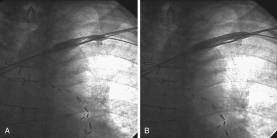
Figure 23-51 Venoplasty of a stenotic subclavian vein that required an aramid fiber (Kevlar) balloon to eliminate the waist.
“Complications” of Subclavian/Innominate Venoplasty
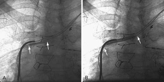
Despite our initial concerns, we find balloon dilation of venous structures remarkably safe as long as the balloon is never used until the wire is advanced successfully to the PA. Figure 23-54 illustrates the potentially catastrophic consequences of not heeding this axiom; in A the wire position appeared satisfactory, but it would not advance to the PA, the tip apparently stuck in the RA; the LAO view in B illustrates how deceptive wire position can be in the AP projection. Figures 23-42 and 23-43 illustrate the consequence of not abiding by the rule when using progressively larger dilators (not venoplasty).
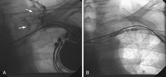
In the case of dilating at the site of stenosis associated with existing leads, concern with safety is understandable. Because the stenosis and leads are surrounded by fibrous tissue, it is fibrous tissue, not a vein, that is being dilated. In addition, it is helpful to consider the relative trauma inflicted by extraction of a lead with a 14F to 16F laser sheath that vaporizes the tissue surrounding the lead. By comparison, balloon venoplasty in the same area is much less traumatic. We have seen contrast staining related to our attempts to manipulate a wire through the stenosis, but our patients have experienced no clinically significant complications (Fig. 23-55). When contrast staining occurs, we continue the procedure and perform venoplasty as long as we can move the wire across the stenosis.
Training Required to Perform Venoplasty
Box 23-6 lists key elements in crossing and dilating stenotic/occluded subclavian veins.
Box 23-6
Key Elements in crossing and dilating stenotic/occluded subclavian veins