CHAPTER 15 Individualized Unicompartmental Knee Arthroplasty


Femoral Components
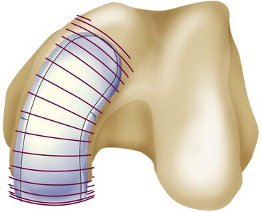
The overall goal of selecting a femoral component is optimal fit. The femoral component should not overhang, but it should be wide enough and match the geometry without impingement of the medial spine or the posterior cruciate ligament. The transition to the femoropatellar joint should be smooth, not prominent, and the femoral component should not be too long, specifically on the lateral side to avoid patellofemoral (PF) impingement. Hernigou and Deschamps1 reported on 99 unicompartmental arthroplasties (UKAs) with a mean follow-up of 14 years. Of these, 29% were symptomatic due to patellar impingement through the femoral component. In this group, lower Knee Society scores were related to problems climbing stairs. They proposed two failure mechanisms; one may be related to an over-resection off the posterior condyle, which consequently moves the femoral component more anteriorly. They also hypothesized that poor intraoperative judgment of the linea terminalis, which describes the trochleocondylar junction, could lead to oversizing the femoral component. Figure 15–1 shows the transition between the medial and lateral condyles to the trochlea. The linea terminalis is the result of the medial and lateral meniscal impression on the femur and can be seen on lateral radiographs. In Herningou and Deschamps’s series, the trochleocondylar junction was an average of 3 mm anterior on the medial and 4 mm posterior on the lateral side relative to a line representing the slope of the intercondylar roof.1 Berger et al.2 reported the results of 59 UKAs with a follow-up of 11–15 years. The main failure mode was symptomatic patellofemoral osteoarthritis in 10%; this was observed despite a pristine PF joint preoperatively. In a group of 48 living patients who had an average radiographic follow-up of 17 years, Squire et al. reported evidence of PF osteoarthritis in 35 patients (87%).3 A total of 14 knees were revised. Six patients were revised for disease progression, but it was not defined whether this was related to PF osteoarthritis.
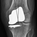
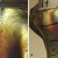
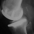
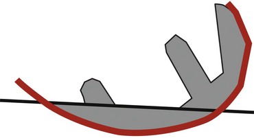
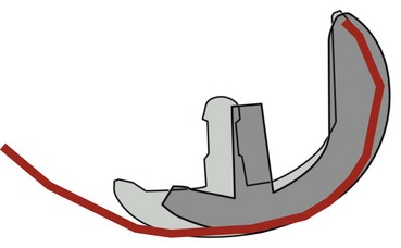
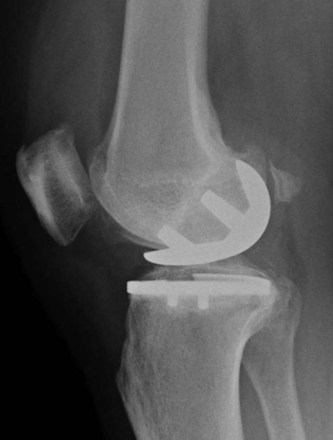
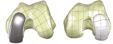
The linea terminalis has to be respected to avoid PF impingement. Both surgical technique and femoral implant design play a role. The distal femoral cut in most systems is not based on an intramedullary rod, but solely on the tibial cut. It is difficult for the surgeon to judge the correct amount of flexion of the distal femoral cut. This step determines the amount of flexion in which femoral component is implanted. If the knee is hyperextended, the distal femoral cutting block cuts in more extension. If the knee is held in more flexion, the component results in a more flexed position. However, the tibial cut can vary depending on whether there is more or less slope, which additionally contributes to more or less flexion or extension. Individualized femoral jigs may help to resolve this source of surgical error. Figure 15–2 shows a femoral component in too much flexion, resulting in PF impingement. All three studies cited above reported increasing PF osteoarthritis in the second decade. All studies used an only-femoral component (Fig. 15–3), which means that the anterior edge is not curved below the subchondral bone. This is in contrast to a recessed femoral component where the edge of the implant extends below the subchondral bone as shown in Figure 15–4. Using a recessed single-radius femoral component, progression of PF osteoarthritis was not seen in a series with a follow-up between 10 and 20 years.4 It remains unclear, since there is no reported 10- to 20-year follow-up series of a tapered J-curve design, whether this is related to the recesses design itself or to the single-radius design. The single-radius femoral implant restores the posterior condylar offset by balancing the flexion gap prior to the extension gap, so the surgical technique is very focused on restoring the posterior condyle. Additionally, its shorter design, replacing only the posterior condyle, may increase femoropatellar offset, which may result in decreasing PF stresses and thereby reducing the likelihood of PF osteoarthritis. However, since PF peak stresses are lowest in extension and increase during flexion,5,6 J-curve femoral components reconstructing the posterior condyle should achieve the same offset compared to a single-radius design (see Fig. 15–4). Restoring the cylindrical posterior condyle,7 therefore, should not result in significantly different PF stresses.
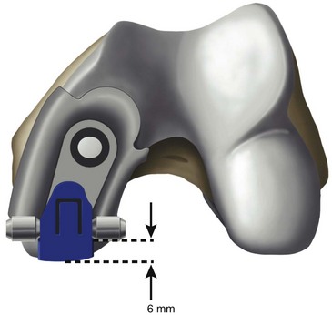
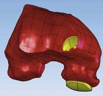
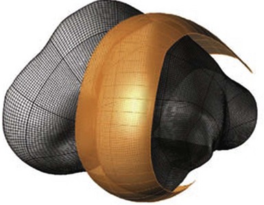
Only-femoral designs may be more susceptible to PF osteoarthritis as a failure mode in the second decade due to impingement between the patella and the edge of the femoral implant. This may be additionally enhanced with the decreasing of cartilage thicknesses as we get older. Individualized UKAs have several advantages compared to off-the-shelf implants: computed tomography (CT) data are utilized to identify the linea terminalis and the implant is designed with respect to the transition to the PF joint with short lateral and longer medial components. The length of the components is related to the restoration of the posterior condyle. A surgical plan provides detailed information on how much bone needs to be resected off the posterior condyle. An example of 6 mm of posterior condylar resection is shown in Figure 15–5. Therefore, an incidental too-anterior placement of the femoral component is addressed by preoperative planning, individualized femoral cutting blocks, and cross-checking through the correct amount of resected bone. In order to address the problem of PF impingement, the anterior edge is recessed below the subchondral bone. Figure 15–6 shows a three-dimensional model demonstrating this design feature.
Width
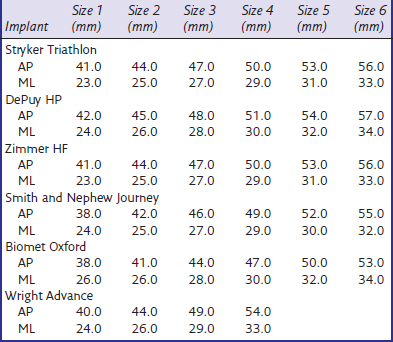
The medial condyle appears narrower and the lateral condyle wider. Some authors, such as Yoshioka et al.,8 could not find a difference. Others described a wider lateral condyle: Mensch and Amstutz9 described an average width of 26.6 mm for the medial condyle and 26.9 mm for the lateral condyle in 30 cadaver knees. Erkman and Walker10 studied 50 radiographed knees and found similar measurements, but values were 10% larger, suggesting magnification differences. We found an average medial condylar width of 26.1 mm (range, 21–32 mm) and an average lateral condylar width of 28.5 mm (range, 22–36 mm) on 48 CT scans.11 Our data are very similar to published data. Looking at off-the-shelf femoral components (Table 15–1), the width is narrower compared to the femoral condyles’ dimensions. This is necessary to allow the surgeon to find the best implant placement and fit, since the bone is cut to fit the implant. The advantage of individualized femoral components are wider femoral components. However, whether this will be an advantage resulting in better long-term results with less femoral loosening still has to be proven. There may, however, be an advantage in heavier patients in that a wider femoral component reduces the overall stresses on implant and fixation.
Table 15–1 Minimum and Maximum Widths of Currently Available U.S. Femoral Components
| Implant | Minimum Width (mm) | Maximum Width (mm) |
|---|---|---|
| Stryker Triathlon | 19.0 | 24.0 |
| DePuy HP | 18.0 | 25.0 |
| Zimmer HF | 21.0 | 26.0 |
| Smith and Nephew Journey | 18.0 | 25.0 |
| Biomet Oxford | 19.0 | 23.0 |
| Wright Advance | 19.0 | 22.0 |
Geometry
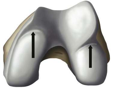
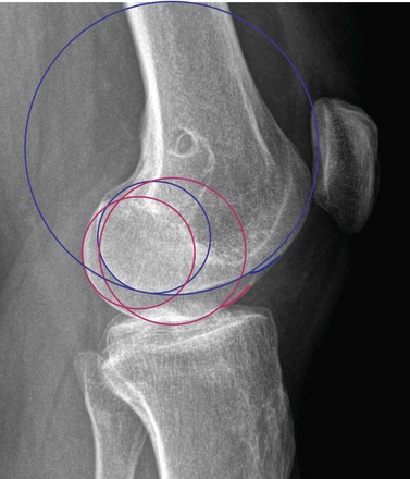
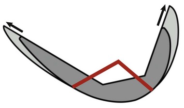
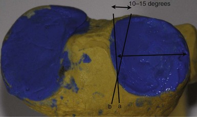
Medial and lateral condyles differ in form and appearance; the anterior edges of both menisci result in an indentation of the inferior surface of both condyles, which is more prominent on the lateral side and represents the anterior part of the J-curve.12 In all implant designs, this anterior part of the J-curve is changed, removing the indentation to reflect the absence of the menisci. The posterior two parts represent two different radii with a constant ratio of 2 : 1.12 Mensch and Amstutz9 found similar values of 1.9 : 1. The first radius, which is larger laterally than medially, represents the weight-bearing surface between extension and 45° and the posterior radius between 45° and 120°. The anterior of the two radii of the lateral condyle averaged 5.9 mm more than the medial condyle (Fig. 15–7). The posterior radii are very similar.9 Prosthetic replacement with equal radii diminishes the lateral and increases the medial condylar anterior radii and may affect knee kinematics.9 Howell et al. compared the posterior radii of medial to those of lateral condyles, and found no significant difference between medial and lateral radii,13 confirming the findings of Shinno and of Mensch and Amstutz for the posterior condyles of the two radii.9,12 Eckhoff et al. observed the cylindrical geometry of the posterior condylar radius and found slightly larger medial condyles.7 While both make arguments for a single-radius designed femoral component, the work of Shinno and of Mensch and Amstutz clearly underlines the importance of describing all parts of the femoral J-curve. The posterior two arcs have different radii, and Eckhoff et al. and Howell et al. described only the very posterior part, which is important between 45° and 120°. A single-radius design does not match the J-curve, but only the posterior radius which is the smallest radius.9,12 Since the ratio between the two radii is constant, there may be an argument for the off-the-shelf implant (Fig. 15–8). However, there is a difference between the more anterior two radii of the medial and lateral femoral condyles that warrants different medial and lateral femoral condylar designs. The lateral anterior radius is twice as large as the medial.
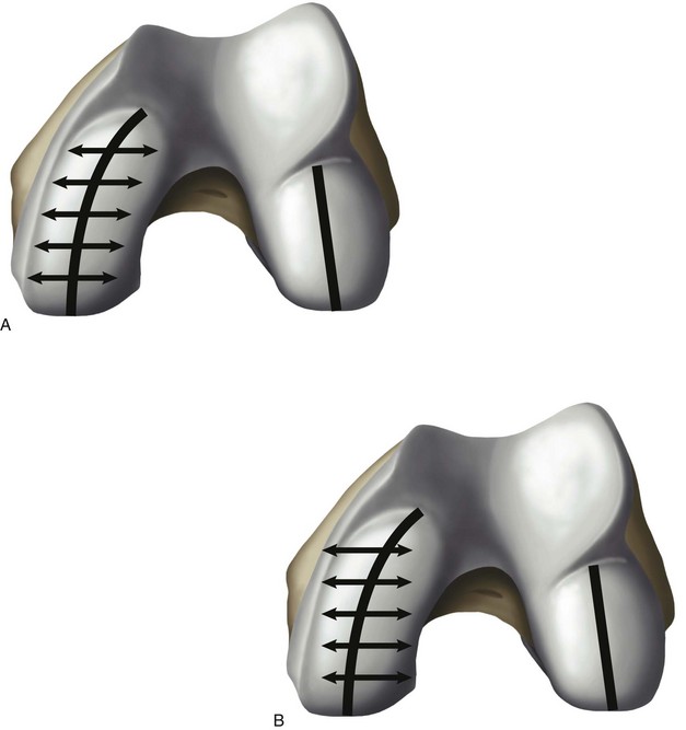
Individualized femoral components offer a solution to address these different condylar geometries, and therefore have the potential to improve knee kinematics and to restore a close-to-normal ligament tensioning. Just by looking at the medial and lateral condyle, there are two additional variations of the shape and geometry of both condyles to be observed. First, the medial condyle extends from the posterior condyle to the transition to the femoropatellar joint appearing not straight, but rather curved with the proximal part pointing more toward the notch. However, the lateral condyle appears less curved. Most available implants are asymmetric, and one could argue it would be preferable to use a more curved asymmetric femoral component to replace the medial condyle, while using a less curved or almost straight component for the lateral side (Fig. 15–9). The only two remaining symmetric implants on the U.S. market are the Biomet Oxford and the Wright Advance. Biomet’s Oxford is contraindicated for the lateral side, but could be used in combination with a fixed-bearing tibial tray. However, no manufacturer offers this option, and it is solely at the surgeon’s discretion to choose implants for best fit between medial and lateral condyles. Individualized implants solve the different shape and geometry of the medial and lateral condyles. Another problem of off-the-shelf femoral components is the way femoral component sizes grow. We know the J-curve has three different elements with a defined ratio of the posterior two radii.9,12 Most implant sizes are not a true magnification of the J-curve. Figure 15–10 shows one example of how larger and smaller sizes are generated. The central third of the J-curve, which is specific to each manufacturer, does not change, and the posterior and anterior thirds are elongated evenly with larger sizes. This concept does not really respect the anatomic principle of the three parts of the J-curve and can result in incomplete coverage of the posterior condyle (see Fig. 15–10).
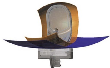
Individualized femoral components are based on the individual J-curve 3.5 mm above the subchondral bone (Fig. 15–11). This represents the necessary thickness for the femoral component for mechanical strength, but on the other side it restores the individual joint surface. Each individual J-curve receives an engineered coronal radius (Fig. 15–12) to optimize the tibial contact area (Fig. 15–13). The mean contact area and the mean contact stress showed comparable values to off-the-shelf fixed-bearing implants during heel strike, toeoff, and midstance positions, with small standard deviations.14 Steklov et al. concluded that a constant coronal curvature can be applied to individualized J-curves to combine unique benefits of individualized implants with proven concept for minimizing polyethylene wear.14
Tibial Plateau
Medial and lateral tibial joint surfaces are not similar in their geometry. This prompts the question whether the use of the same implant is justified. We presented CT data on 48 patients (24 females and 24 males) showing that the medial tibial plateau measured 5 mm below the lowest point is different, with an ML/AP ratio of around 0.6 while that of the lateral tibial plateau is 0.7.11 This means the medial tibial plateau is more oval and the lateral side is rounder. Servien et al.15 found similar AP/ML ratios of 0.56 for the medial side and 0.63 for the lateral side. Their measurements are smaller compared to our data, but their series had five times more females than males, resulting in smaller values. Surendran et al.16 studied CT scans of 100 (50 males and 50 females) cadavers and described the dimensions 6 mm below the lowest point of the medial tibia with a slope of 7°. They found reasonable coverage with off-the-shelf implants for the Korean population. There was only one male with an AP length of more than 58 mm. No Korean male had a tibial cut wider than 33 mm, which is different from our series, where 8 of 25 males had a medial tibia of more than 33 mm. They did not study the lateral tibial side at all. Comparing our measurements with the actual dimensions of tibial plateaus in commercial implants available in the United States (Table 15–2), we found for the medial tibial plateau that 13% of males have not enough AP coverage, and 25% of males and 4% of females have too much ML coverage. On the lateral side, 4% have not enough AP and 27% not enough ML coverage. Servien et al.15 did not compare the actual tibial plateau measurements with implant dimension, but they concluded that optimal AP coverage may lead to medial overhang.
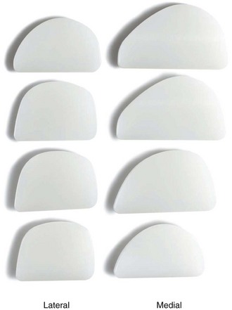
Besides looking at the actual dimensions, the shape of the tibial plateau varies too. We know the lateral tibial plateau is not as D-shaped as the medial—it is instead rounder. Fitzpatrick et al. observed the shape of the tibial cuts 5 mm below the joint surface in 34 CT scans, and calculated how much cortical rim would be covered by a D– and/or a teardrop-shaped implant.17 The D-shaped implant was better than the teardrop-shaped implant, with a maximum of 74% cortical coverage on the medial side and 60.5% on the lateral side. They used a theoretical model to calculate how much cortical coverage could be obtained with an optimized implant design and concluded that 76% could achieve cortical rim coverage and felt there was room for improvement in implant design. Individualized implants have the advantage of being able to reproduce each patient’s geometry. Figure 15–14 shows different geometries observed in my recent patients. Specifically, the rounder geometry of the lateral tibial plateau is quite obvious and explains the findings of poor cortical coverage more so on the lateral tibial plateau that Fitzpatrick et al. described. Shortcomings of off-the-shelf implants are reflected in variations of surgical techniques published in the past. There are two recommendations: one is to place the lateral tibial plateau more mesial (moving it closer to the lateral tibial spine) and leaving the very lateral aspect of the tibial condyle uncovered.18 The second recommendation is to internally rotate the tibial component for better coverage.19 Figure 15–15 shows the effect on a sawbones of internally rotating the lateral tibial tray to improve lateral cortical coverage. However, this may lead to decreased coverage toward the posterior cruciate ligament (PCL) and may cause the lateral femoral condyle to roll backward with flexion toward the PCL. Individualized tibial trays solve this problem.
Ligament Balancing
The reconstruction of the geometry of femoral and tibial articulating surfaces may play a more important role in total knee arthroplasty and more so in UKA to restore more physiologic kinematics and ligament tensioning. Unicompartmental arthroplasties restore close-to-normal knee kinematics, whether they are mobile bearing20 or fixed bearing.21 The Oxford experience taught surgeons that the balancing of the medial collateral ligament has to be obtained within 1 mm to avoid meniscal bearing dislocation and to restore normal joint kinematics. This is a little less than the recommended 1–3 mm.22 Exact numbers of how much play or laxity should be obtained after knee arthroplasty remain unclear. Recently, one implant introduced a tensiometer and early results demonstrated that women had 10–15N less tension compared to men.23 However, this device resulted in 4.9% dislocation rate in mobile-bearing UKA within 2 years. One magnetic resonance imaging study showed that, in normal living knees, a lateral joint gap opened under the stress of 6.7 mm versus 2.1 mm medially. There was a tendency that female gaps had more laxity, but it did not reach statistical significance. The lateral side is 4.6 mm laxer in flexion, and authors questioned the concept of rectangular flexion gaps in total knee replacement.24 However, this confirms that the balancing of medial and lateral UKAs in flexion should be different and looser laterally. In extension, the balancing under stress should be around 1–2 mm medially and 2–3 mm laterally.
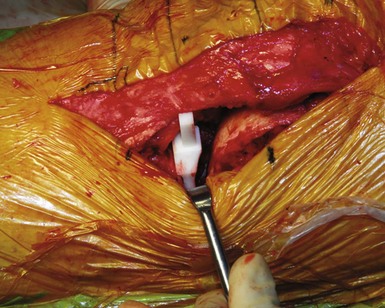
After removing all osteophytes, it is important during the balancing step to avoid tightness. This would result in overcorrection and potentially lead to progressive osteoarthritis of the contralateral side. Most off-the-shelf implants use some type of spacer blocks to allow precise balancing. Individualized UKAs introduce an individualized spacer-block concept. After the removal of osteophytes and residual articular cartilage, individual chips in various thicknesses designed to match the surface topography of the tibia are inserted. Figure 15–16 shows an inserted navigation chip with a gap opening of about 2–3 mm. The chip can be exchanged to be thinner or thicker, depending on the surgeon’s liking. The thicker the chip, the less bone is resected off the tibia, and vice versa.25 The gap opening after the components are cemented equals the gap opening during the balancing step.
Alignment
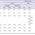
Restoration of coronal alignment within 2.4–7.2° of valgus results in the lowest failure rate of 0.5% in total knee replacement.26 Choong et al.27 demonstrated, in a randomized prospective study comparing computer-assisted navigation to hand navigation in total knee replacement, that International Knee Society and Short Form-12 scores were significantly better at 6 weeks and 3, 6, and 12 months if coronal alignment within 3° of neutral was achieved. Better alignment correlates with better knee function and improved quality of life.27 Improvement of coronal alignment using non–image-based navigation was demonstrated in a randomized prospective study of UKAs, resulting in 95% with an alignment with a range between 0° and 4°. However, no study has yet shown better alignment to improve clinical outcome in UKA. Individualized instruments, using the mechanical alignment of femur and tibia published recently, resulted in correction of the varus coronal alignment from 7° to 1° in 32 individualized UKAs. Also the medial proximal tibial angle was corrected from 87° to 89°, demonstrating the high accuracy of single-use, individualized, and prenavigated surgical instrumentation.28
 ). A surgical plan provides detailed information to the surgeon for each patient to optimize implant position. Width and geometry and the differences of the medial and lateral condyles are respected in individualized femoral implants. Deficiencies of tibial implant sizes for large males on the medial side as well as on the lateral side are addressed. Long-term results for lateral UKA are needed to demonstrate the superiority of this novel technology.
1 Hernigou P, Deschamps G. Patellar impingement following unicompartmental arthroplasty. J Bone Joint Surg [Am]. 2002;84:1132-1137.
2 Berger RA, Meneghini RM, Sheinkop MB, et al. The progression of patellofemoral arthrosis after medial unicompartmental replacement: results at 11 to 15 years. Clin Orthop Relat Res. 2004;428:92-99.
3 Squire MW, Callaghan JJ, Goetz DD, et al. Unicompartmental knee replacement: a minimum 15 year followup study. Clin Orthop Relat Res. 1999;367:61-72.
4 Svard UC, Price AJ. Oxford medial unicompartmental knee arthroplasty: a survival analysis of an independent series. J Bone Joint Surg [Br]. 2001;83:191-194.
5 Huberti HH, Hayes WC. Patellofemoral contact pressures: the influence of q-angle and tendofemoral contact. J Bone Joint Surg [Am]. 1984;66:715-724.
6 Marder RA, Swanson TV, Sharkey NA, Duwelius PJ. Effects of partial patellectomy and reattachment of the patellar tendon on patellofemoral contact areas and pressures. J Bone Joint Surg [Am]. 1993;75:35-45.
7 Eckhoff DG, Bach JM, Spitzer VM, et al. Three-dimensional mechanics, kinematics, and morphology of the knee viewed in virtual reality. J Bone Joint Surg [Am]. 2005;87(Suppl 2):71-80.
8 Yoshioka Y, Siu D, Cooke TD. The anatomy and functional axes of the femur. J Bone Joint Surg [Am]. 1987;69:873-880.
9 Mensch JS, Amstutz HC. Knee morphology as a guide to knee replacement. Clin Orthop Relat Res. 1975;112:231-241.
10 Erkman MJ, Walker PS. A study of knee geometry applied to the design of condylar prostheses. Biomed Eng. 1974;9:14-17.
11 Fitz W, Losina E. Why we need individualized partial knee replacements. Vienna, Austria: Presented at the 9th EFORT meeting; 2009.
12 Shinno N. Statico-dynamic analysis of movement of the knee. I. Modus of movement of the knee. Tokushima J Exp Med. 1961;8:101-110.
13 Howell SM, Howell SJ, Hull ML. Assessment of the radii of the medial and lateral femoral condyles in varus and valgus knees with osteoarthritis. J Bone Joint Surg [Am]. 2010;92:98-104.
14 Steklov N, Slamin J, Srivastav S, D’Lima D. Unicompartmental knee resurfacing: enlarged tibio-femoral contact area and reduced contact stress using novel patient-derived geometries. Open Biomed Eng J. 2010;4:85-92.
15 Servien E, Saffarini M, Lustig S, et al. Lateral versus medial tibial plateau: morphometric analysis and adaptability with current tibial component design. Knee Surg Sports Traumatol Arthrosc. 2008;16:1141-1145.
16 Surendran S, Kwak DS, Lee UY, et al. Anthropometry of the medial tibial condyle to design the tibial component for unicondylar knee arthroplasty for the Korean population. Knee Surg Sports Traumatol Arthrosc. 2007;15:436-442.
17 Fitzpatrick C, FitzPatrick D, Lee J, Auger D. Statistical design of unicompartmental tibial implants and comparison with current devices. Knee. 2007;14:138-144.
18 Scott R. Total Knee Arthroplasty. Philadelphia: WB Saunders; 2005.
19 Pennington DW, Swienckowski JJ, Lutes WB, Drake GN. Lateral unicompartmental knee arthroplasty: survivorship and technical considerations at an average follow-up of 12.4 years. J Arthroplasty. 2006;21:13-17.
20 Price AJ, Rees JL, Beard DJ, et al. Sagittal plane kinematics of a mobile-bearing unicompartmental knee arthroplasty at 10 years: a comparative in vivo fluoroscopic analysis. J Arthroplasty. 2004;19:590-597.
21 Patil S, Colwell CWJr, Ezzet KA, D’Lima DD. Can normal knee kinematics be restored with unicompartmental knee replacement? J Bone Joint Surg [Am]. 2005;87:332-338.
22 Whiteside LA. Making your next unicompartmental knee arthroplasty last: three keys to success. J Arthroplasty. 2005;20(4 Suppl 2):2-3.
23 Hoffmann F, Campbell D, et al. Ligament balancing in unicondylar knee prothesis: early clinical results of a multicentre study on 175 cases. Vienna, Austria: Presented at the 9th EFORT meeting; 2009.
24 Tokuhara Y, Kadoya Y, Nakagawa S, et al. The flexion gap in normal knees: an MRI study. J Bone Joint Surg [Br]. 2004;86:1133-1136.
25 Fitz W. Unicompartmental knee arthroplasty with use of novel patient-specific resurfacing implants and personalized jigs. J Bone Joint Surg [Am]. 2009;91(Suppl 1):69-76.
26 Fang DM, Ritter MA, Davis KE. Coronal alignment in total knee arthroplasty: just how important is it? J Arthroplasty. 2009;24(6 Suppl):39-43.
27 Choong PF, Dowsey MM, Stoney JD. Does accurate anatomical alignment result in better function and quality of life? Comparing conventional and computer-assisted total knee arthroplasty. J Arthroplasty. 2009;24:560-569.
28 Koeck FX, Beckmann J, Luring C, et al. Evaluation of implant position and knee alignment after patient-specific unicompartmental knee arthroplasty. Knee. 2010;August 3. [Epub ahead of print]