[level-membership-for-emergency-medicine-category]Chapter 80
Implantable Cardiac Devices
Perspective
Electrical cardiac pacing for the management of bradyarrhythmias was first described in 1952, and permanent transvenous pacing devices were introduced into clinical practice in the early 1960s.1 The first devices for endocardial defibrillation were implanted in surviving victims of sudden cardiac death in 1980.2 Implanted electrical devices for the management of cardiac dysrhythmias have changed rapidly over the years, with both increasing complexity and miniaturization. Survey data from 2002 indicated that approximately 612 new pacemakers per million population were implanted in the United States.3 Indications for the use of permanent pacemakers in the management of congenital and acquired heart disease include cardiac resynchronization therapy for heart failure.4–6
A number of large clinical trials comparing implantable cardioverter-defibrillators (ICDs) with antiarrhythmic drugs for the prevention of sudden cardiac death resulting from ventricular dysrhythmias have indicated that ICDs significantly improve survival.7,8 Such studies have led to a dramatic increase in ICD implantations, and it is estimated that there are more than 125,000 new ICD implants annually in the United States.9 The widespread use of these devices ensures that the emergency physician frequently encounters such patients, often with symptoms that may be related to malfunction of the pacemaker or ICD.
Indications for Permanent Pacemakers and Antiarrhythmia Devices
Guidelines for the implantation of these devices have been developed by a joint task force of the American Heart Association (AHA) and the American College of Cardiology (ACC) and are periodically updated.10 With use of an evidence-based approach, recommendations are categorized as class I, II, or III. Class I includes conditions for which there is general agreement that a device should be implanted. A class II recommendation includes conditions for which these devices are frequently used but for which there is disagreement about their need or benefit. Class III is reserved for conditions for which there is general agreement that a device is not needed.
In the case of pacemaker therapy, additional factors are considered when selecting the mode of pacing and include, but are not limited to, overall health, lifestyle, and occupation of the patient. Class I indications for a permanent pacemaker or ICD are listed in Boxes 80-1 and 80-2. In general, pacing is recommended for patients with symptomatic heart block, symptomatic sinus bradycardia, and atrial fibrillation with a symptomatic bradycardia (low ventricular response rate) in the absence of medications that affect atrioventricular (AV) conduction. Controversial indications include pacing in patients with syncope, heart block, or fatigue in the presence of some conduction disease or bradycardia. The likelihood of a patient’s improvement after pacing can be assumed only if the symptoms can be closely correlated with inadequate rate.
Pacemaker Terminology
A letter code, initially established in 1974 and revised as technology advances, standardizes nomenclature for pacemakers.11 Table 80-1 includes an explanation of the five-letter code scheme and the standard abbreviations in each category. The first three code letters are used most commonly. Using this table, one should be able to understand the features of any pacing mode. For example, a VDD pacemaker is capable of pacing only the ventricle, sensing both atrial and ventricular intrinsic depolarization, and responding by dual inhibition of both atrial and ventricular pacing if intrinsic ventricular depolarization occurs; a paced ventricular beat is triggered in response to a sensed intrinsic atrial depolarization. The codes of a permanent pacemaker that are used most frequently and the indications, advantages, and disadvantages of each are listed in Table 80-2. Detailed algorithms for matching a patient with a pacemaker exist.10 The majority of permanent pacemakers are dual chamber and often rate adaptive.12
Table 80-1
*In the triggered response mode, the pacemaker discharges or fires when it recognizes an intrinsic depolarization. As a result, pacemaker spikes occur during inscription of the QRS complex. Because this mode results in high energy consumption and a shortened battery life and because the sensing response can be misinterpreted as pacemaker malfunction, this sensing mode is not used with modern pacemakers.
Pacemaker Components
Permanent pacemakers have endocardial leads that are positioned in contact with the endocardium of the right ventricle and, in the case of a dual-chamber device, the right atrium, with a subclavian or cephalic vein approach used for insertion. Occasionally, an epicardial lead may be implanted during open-heart surgery performed for another indication, such as prosthetic valve insertion or correction of a congenital cardiac defect. Pacemaker leads, like power sources, continue to undergo major technical improvements.1 Innovations include resilient plastic insulation surrounding the electrodes that reduces the chance of complete lead disruption or breakage (resulting in failure to pace or sense) and the chance of partial fracture (resulting in a “make or break” contact with intermittent failure to sense or pace). Despite these advances, problems with the electrical circuitry remain the most common cause of pacemaker malfunction.13 A lead capable of active fixation is more commonly used in patients with cardiomyopathies and right ventricular dilation complicated by tricuspid regurgitation.
Pacemaker leads may be either bipolar or unipolar in configuration. A bipolar endocardial lead has both the negative (distal) and the positive (proximal) electrodes, separated by approximately 1 cm, within the heart. A unipolar lead has the negative electrode in contact with the endocardial surface, and the positive pole is the metallic casing of the pulse generator. Each lead system has potential advantages and disadvantages.1 The unipolar configuration is not compatible with ICD systems and is prone to oversensing of myopotentials and electromagnetic interference but is of smaller diameter and less susceptible to fracture. The bipolar configuration is compatible with ICD systems but is larger and more prone to lead fractures. Oversensing, however, is rarely a problem. The selection of lead configuration usually depends on the experience and preference of the operator.
The Standard Electrocardiogram during Normal Cardiac Pacing
The modern pacemaker has two basic functions: to stimulate the heart electrically and to sense intrinsic cardiac electrical activity. Additional functions are available and are noted in the pacemaker code system (see Table 80-1, letters 4 and 5). The pacemaker delivers an electrical stimulus to either the atrium or the ventricle if it does not recognize (sense) any intrinsic electrical activity from that chamber after a selected time interval. This interval is usually programmed at the time of implantation and can be changed noninvasively at a later time, if necessary, with use of a programming and “interrogating” device provided by the pacemaker manufacturer. If the pacemaker recognizes or senses an intrinsic atrial depolarization (P wave) or ventricular depolarization (QRS complex), it inhibits or resets its output to prevent competition with the underlying intrinsic rhythm. The stimulus intensity and sensing threshold (amplitude of electrical activity that is detected as being intrinsic) are typically set at the time of implantation but can also be reprogrammed later.
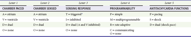
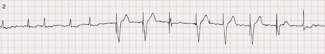
The two basic functions of a pacemaker can be easily recognized and confirmed on a standard 12-lead electrocardiogram (ECG) or rhythm strip. The normal function of a single-chamber VVI pacemaker is most easily recognized (Fig. 80-1). After a programmed interval is surpassed during which intrinsic ventricular activity does not occur, a pacer “spike” or stimulus artifact appears. The pacer spike is a narrow deflection that is usually less than 5 mm in amplitude with a bipolar lead configuration and usually 20 mm or more in amplitude with a unipolar lead. A wide QRS complex appears immediately after the stimulus artifact. Depolarization begins in the right ventricular apex, and the spread of excitation does not follow normal conduction pathways. Characteristically, a left bundle branch block conduction pattern is seen. A right bundle branch pattern is abnormal and suggests lead displacement. In VVI pacing the paced QRS complexes are independent of intrinsic atrial depolarization if present (AV dissociation).
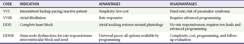
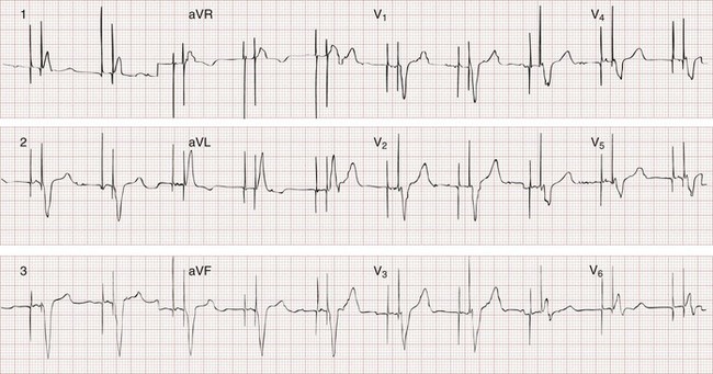
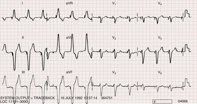
The recognition of normal dual-chamber pacing is more complex owing to the interactive sensing and pacing of the right atrium and ventricle (Fig. 80-2).14 Pacing intervals are preprogrammed, may be changed noninvasively at a later time, and are generally specific to the patient’s needs. Pacing rates and delay intervals typically vary from patient to patient. Dual-chamber devices are typically used in patients with nonfibrillating atria coupled with intact AV conduction. A normal-appearing QRS complex may follow an intrinsic “P” wave as a result of normal sinoatrial node discharge if the intrinsic atrial depolarization is conducted to the ventricles. The intrinsic p wave and QRS complex inhibit the atrial and ventricular circuitry. A normal QRS complex follows a paced p wave if the paced atrial beat is conducted through the AV node and the programmed AV delay period is not exceeded. If it is not conducted to the ventricles (AV delay period exceeded), the pacemaker stimulates the ventricle, resulting in a paced p wave and a wide, paced QRS complex with left bundle branch block configuration.
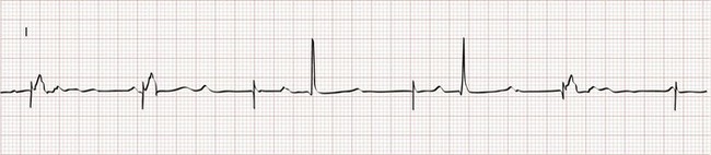
Recognition of the interactivity of the paced chambers is important. A paced p wave may be mistaken for failure to sense or pace, and malfunction may be diagnosed when it is not present (pseudomalfunction). In addition, if the programmed rate of the pacemaker approximates the patient’s intrinsic heart rate, fusion of paced and native beats may occur and represents another common type of pseudomalfunction (Fig. 80-3).
Complications of Implantation
Pacemaker implantation is a surgical procedure and, like all surgery, carries a risk of infection; the presence of a foreign body enhances this risk. The incidence of infection is small—approximately 2% for wound and subcutaneous pacemaker “pocket” infection and approximately 1% for bacteremia with sepsis. The presence of a foreign body complicates management, and few cases of bacteremia that develop after implantation can be managed with antibiotics alone. In most instances, reimplantation and replacement of the lead system are necessary.15
When a local infection or bacteremia is suspected, blood cultures should be obtained and intravenous antibiotic therapy initiated. Staphylococcus aureus and Staphylococcus epidermidis are isolated in approximately 60 to 70% of cases. Empirical antibiotic therapy should include vancomycin pending culture and sensitivity data. If blood cultures are positive, the pulse generator and pacemaker lead are usually removed, temporary transvenous pacing is performed, and intravenous antibiotic therapy is continued for 4 to 6 weeks. The permanent pacemaker and lead are subsequently reimplanted.15
Thrombophlebitis
The incidence of venous obstruction associated with permanent transvenous pacemakers ranges from 30 to 50%, with approximately one third of patients having complete venous occlusion.16 Thrombosis of varying degrees can involve the axillary, subclavian, and innominate veins or the superior vena cava (SVC). The site of insertion does not appear to affect the incidence of this complication. Chronic thrombosis of the veins of the upper arm is common and usually asymptomatic owing to extensive venous collateral circulation.
The “Pacemaker Syndrome”
These symptoms are termed the pacemaker syndrome.17 The cause of this syndrome is the loss of AV synchrony and the presence of ventriculoatrial conduction, and it is most commonly encountered in the setting of VVI pacing. It is also described with the DDI mode. With VVI pacing, the ventricle is electrically stimulated and depolarized, resulting in ventricular systole. If sinus node function is intact, the atria can be depolarized by a sinus impulse and contract when the tricuspid and mitral valves are closed. This contractile asynchrony results in an increase in jugular and pulmonary venous pressures and may produce symptoms of congestive heart failure.
Approximately 20% of patients report symptoms suggesting the pacemaker syndrome after pacemaker insertion. In most instances, symptoms are mild and patients adapt to them. In approximately one third of these patients, symptoms are severe. Treatment usually requires replacing a VVI pacemaker with a dual-chamber pacemaker or lowering the pacing rate of the VVI unit. If symptoms occur in a patient paced in the DDI mode, optimizing the timing of atrial and ventricular pacing is usually required. Patients appear to prefer dual-chamber pacing to the VVI modality.18 Persistence or worsening of symptoms of congestive heart failure may also be caused by the altered ventricular activation sequence inherent with stimulation of the right ventricle.19 Biventricular pacing may be required in selected patients.
Pacemaker Malfunction
The term pacemaker malfunction refers specifically to problems with the circuitry or power source of the pulse generator, the pacemaker lead (most commonly displacement or fracture), or the interface between the pacing electrode and the myocardium (pacing or sensing threshold). In addition, environmental factors, such as extracardiac or extracorporeal electrical signals, may interfere with normal pacemaker function.20,21 With use of the standard ECG, pacemaker malfunction can be separated into three broad categories: (1) failure to capture (no pacemaker spikes or spikes not followed by an atrial or ventricular complex), (2) inappropriate sensing (oversensing or undersensing spikes occur prematurely or do not occur even though the programmed interval is exceeded), or (3) inappropriate pacemaker rate. Symptomatic pacemaker malfunction after implantation occurs in less than 5% of patients and is rarely immediately life-threatening. Malfunction is most commonly a result of inappropriate sensing, followed by failure to capture.17 Typical presentations and causes of pacemaker malfunction are listed in Box 80-3.
In the context of suspected pacemaker malfunction, knowledge of the pacing modalities (see Table 80-1) and what is normal for a given pacing modality are critical when the ECG is reviewed. Fortunately, patients are provided with important identifying information, usually in the form of a wallet card, after pacemaker implantation. The most important information is provided in the five-letter code. If this information is not available, a standard posteroanterior and a lateral chest radiograph can provide critical information. A single lead in the apex of the right ventricle indicates a VVI pacemaker. With VVI pacing, only one stimulus artifact or spike is seen with each stimulated ventricular depolarization (see Fig. 80-1). If sinus node activity is present, the paced QRS complex is dissociated from the intrinsic P waves. If separate leads are identified in the right atrium and right ventricle, the pacing modality is most often DDD or DVI, and paced p waves and QRS complexes (two spikes for each QRS complex) are seen (see Fig. 80-2). Although DDD and DVI units are capable of pacing both the right atrium and the right ventricle, only one spike may be seen (Fig. 80-4). Failure to identify two spikes with a DDD or DVI unit can represent normal pacemaker function.
Failure to Capture
Failure to capture may range from the complete absence of pacemaker spikes to spikes not followed by a stimulus-induced complex (Fig. 80-5). A complete absence of pacemaker spikes may result from battery depletion, fracture of the pacemaker lead, or disconnection of the lead from the pulse generator unit.
Current lithium-iodine batteries are not subject to sudden power failure, and they display typical end-of-life functional changes over a period of months to a year before complete depletion.1 Usually the first sign of voltage depletion is a decrease in the programmed pacing rate. This change is gradual and should be detected during the regular follow-up evaluations that pacemaker patients receive. When voltage output falls to a critical level, stimulus strength falls below the required threshold, and failure to capture or intermittent failure to capture may be observed late in battery life. As a result, urgent or emergent battery replacement is rare.
Lead fracture, which is uncommon with the current polyurethane lead coating,1 produces an insulation break, resulting in failure to capture as a result of current leakage. It can be detected as a change in pacing threshold during pacemaker interrogation. Lead fractures occur at predictable locations, usually at the site of attachment to the pulse generator or at abrupt angulations that serve as stress points. Inadequate contact of the lead with the pulse generator can mimic a lead fracture. Occasionally, when a lead fracture is complete or nearly complete, a break in the catheter or its insulation can be detected on an overpenetrated posteroanterior chest radiograph. Loss of lead-pulse generator contact can be detected on the chest radiograph with close inspection of the pulse generator.
Exit block (the failure of an adequate stimulus to depolarize the paced chamber) can also result in failure to pace. Exit block should be considered when the preprogrammed pacing stimulus output fails to result in capture in the presence of a normally functioning pulse generator and an intact lead system. This problem is most commonly a result of changes in the endocardium in contact with the pacing system. Causes include ischemia or infarction of the endocardium in contact with the electrodes; systemic hyperkalemia; and the use of class III antiarrhythmic drugs, such as amiodarone, which affect ventricular depolarization. Although other drugs alter pacemaker threshold, the effect is small and is rarely clinically important.20 At the time of pacemaker insertion, stimulus strength, defined as the amplitude and duration of the electrical output, is always set above the minimum required to result in an artificial electrical depolarization.
Inappropriate Sensing
For a pacemaker to function in a noncompetitive mode, it must be capable of sensing the intrinsic or “native” electrical activity of the heart. The electrical activity that is sensed is determined by the pacing modality (see Table 80-1). Sensing parameters are determined at the time of pacemaker insertion on the basis of the signal size of the intracardiac ECG and can be changed or fine-tuned externally at a later time if needed.
Undersensing
Undersensing is typically recognized electrocardiographically as the appearance of pacemaker spikes occurring earlier than the programmed rate. The spike may or may not be followed by a paced complex, depending on when it occurs during the cardiac refractory period (Fig. 80-6). Failure of a stimulus spike to produce a complex when it occurs during the atrial or ventricular refractory period should not be interpreted as failure to pace.
Oversensing
In rare instances the pacemaker may detect electrical activity that is not of cardiac origin. The result may be intermittent, irregular pacing or an apparent complete absence of pacemaker function. Myopotentials produced by the pectoralis muscle (Fig. 80-7) and extracorporeal electrical signals are frequently oversensed when a unipolar lead system is used. T waves that follow an intrinsic ventricular depolarization are the most common oversensed cardiac signals. Common medical sources of electrical interference include electrocautery, which can cause temporary pacemaker inhibition, and magnetic resonance imaging, which can alter pacemaker circuitry and result in fixed-rate or asynchronous pacing. Electromagnetic interference resulting from close proximity to a microwave oven should not cause pacemaker problems with currently implanted pacemaker units. Interference can be caused by the use of a digital cellular phone.20,21 These devices may cause pacemaker inhibition, inappropriate ventricular tracking, or asynchronous pacing. Malfunction is most commonly seen when the phone is within 10 cm of the pulse generator and often occurs when the phone is applied to the ear ipsilateral to the site of the pacemaker pocket.
Inappropriate Pacemaker Rate
A pacing rate below the programmed rate is a typical finding in pulse generator depletion and does not occur abruptly with lithium-iodine batteries. An extreme increase in pacing rate, the so-called “runaway pacemaker,” is rarely, if ever, encountered with current pacemaker technology and circuitry in which upper rate limits are set (typically 140 beats/min). An “endless loop” tachycardia may develop during dual-chamber pacing when ventriculoatrial conduction occurs, and the resulting retrograde atrial depolarization results in a stimulated or paced ventricular depolarization.22 If atrial flutter develops during dual-chamber pacing, flutter waves may be sensed and tracked, resulting in a rapid, paced ventricular rate. In both instances, the ventricular rate does not exceed its set upper limit. Patients with such rhythms may complain only of palpitations or symptoms of hemodynamic compromise. When such rhythms are detected, magnet application usually converts the pacemaker to a fixed rate in a competitive mode and terminates the tachyarrhythmia.
Management
12-Lead Electrocardiogram
A standard ECG and a long rhythm strip should be obtained in all patients. With bipolar pacing systems, the stimulus artifact may be extremely small and difficult to recognize in some leads (see Fig. 80-4). Inspection of the rhythm strip may reveal failure to sense or pace, a low pacing rate, or an abnormally rapid rhythm, suggesting a pacemaker-mediated tachycardia.
Advanced Cardiac Life Support Interventions
Electrical defibrillation at recommended shock strengths (200, 300, and 360 J) can be safely performed in the patient with a pacemaker.17 If the sternal paddle is placed adjacent to the sternum, it is at a safe distance (>10 cm) from the pulse generator. Alternatively, defibrillation electrodes can be placed in an anteroposterior configuration. A cardiologist or technician should ensure that the pacing parameters of the unit are not altered if the resuscitation is successful. A chest radiograph should also be obtained after resuscitation to ensure that the pacing catheter was not displaced during chest compression, although this is an extremely uncommon occurrence.
Implantable Cardioverter-Defibrillators
The ICD was first used clinically in 1980. Technical refinements in this modality for treating ventricular dysrhythmias have progressed even more rapidly than refinements in the less complex standard pacemaker. A surge in the use of ICDs reflects improved survival with ICDs versus antiarrhythmic therapy in patients at risk for sudden death resulting from ventricular dysrhythmias. Generally accepted indications for ICD implantation are noted in Box 80-2. Many patients still require drug therapy after ICD implantation to suppress ventricular dysrhythmias, minimize the frequency of ICD shocks, improve patients’ tolerance, and decrease energy use, which prolongs ICD life.
Terminology and Components
The typical modern ICD consists of components similar to those in the standard permanent pacemaker namely, a power source, electronic circuitry, and lead system. In addition, the standard ICD has a high-voltage capacitor and complex microprocessor memory.23 The power source is lithium chemistry based with a battery life of 5 to 10 years. The longevity is largely determined by the frequency of shocks. All ICDs are also ventricular pacemakers, providing pacing for bradyarrhythmias.
Malfunction
Patients with ICD malfunction usually come to the ED with a limited number of specific symptoms (Box 80-4).
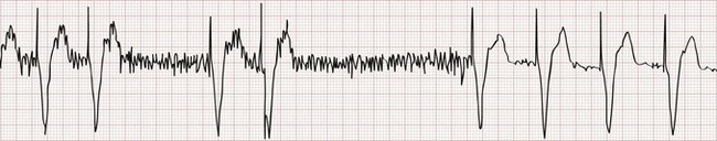
In contrast to patients with a permanent pacemaker, ICD patients are aware of when the ICD discharges to terminate VT or VF. The most common complaint of ICD patients is the occurrence of frequent shocks (i.e., occurring at a rate greater than they are accustomed to).24 An increasing shock rate may be appropriate and not indicative of ICD malfunction if the patient is experiencing an increase in the frequency of VT or VF episodes. An increase in the frequency of episodes may occur in the setting of hypokalemia, hypomagnesemia, ischemia (with or without infarction) related to underlying coronary artery disease, or the proarrhythmic effect of drugs administered to decrease the frequency of ventricular tachyarrhythmias. Many ICD patients, particularly those to whom the technology is new, report that their device discharged, but subsequent device interrogation reveals that no discharge occurred.
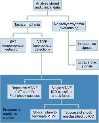
An increase in the shock frequency is a manifestation of ICD sensing malfunction if (1) a supraventricular tachyarrhythmia is inappropriately sensed as VT, (2) shocks are delivered for nonsustained VT, or (3) intracardiac T waves detected by the ICD system are sensed as QRS complexes and the ICD interprets this as an increased heart rate. Temporary ICD deactivation with magnet application may be necessary if oversensing is the problem. Syncope, near-syncope, dizziness, or lightheadedness in the patient with an ICD may indicate undersensing of sustained VT or inappropriately low shock strength to terminate the rhythm. An approach to the evaluation of ICD malfunction is shown in Figure 80-8.
Disposition of the Emergency Department Patient with an Implantable Cardioverter-Defibrillator
As a result of the difficulty in documenting or excluding ICD function or malfunction in the patient with transient symptoms, the device should be interrogated to guide further evaluation and therapy. In cases in which the patient reports a single ICD shock, an assessment for acute cardiac ischemia, worsening of chronic congestive heart failure, symptoms of new-onset heart failure, and electrolyte abnormalities should be performed. In the absence of a change in clinical status, such patients can be discharged in consultation with the managing or consulting cardiologist after timely follow-up is ensured. For patients reporting multiple shocks, interrogation is essential, because in many of these cases the defibrillator has not discharged and the patient is experiencing hiccoughs, diaphragmatic twitching, or other nonelectrical phenomena. In such cases, discharge home is the rule. When multiple defibrillator discharges are confirmed by interrogation, immediate consultation is required along with admission to a monitored setting for extended telemetric observation. If frequent ventricular ectopy is noted, intravenous amiodarone should be given.24 ICD interrogation allows assessment of ICD function and preceding dysrhythmia episodes.25 Reprogramming may be necessary. If a lead problem is detected, reimplantation is required. A magnet can be placed over the ICD to inactivate the defibrillator. This should be done only if the emergency physician is confident that the ICD is delivering inappropriate shocks, such as a supraventricular tachycardia.
Biventricular Pacing
Biventricular pacing, also known as cardiac resynchronization therapy, is a therapy for patients with left-sided heart failure and ventricular dyssynchrony. It is beneficial for patients with New York Heart Association (NYHA) class III or IV heart failure despite optimal medical therapy, a left ventricular ejection fraction of 35% or less, and sinus rhythm with QRS duration of 120 msec or greater.26,27 Left bundle branch block causes an altered sequence of depolarization of the left ventricle such that the interventricular septum contracts before the left ventricular free wall, leading to inefficient mechanical pumping. Biventricular pacing “resynchronizes” the ventricles by simultaneously pacing the left and right ventricles, eliminating the delay in left ventricular free wall contraction and improving systolic function. Right atrial and right ventricular leads are positioned as for conventional atrial and univentricular pacing. The left ventricular lead is positioned in a left ventricular epicardial location via the coronary sinus and veins, preferably in a posterolateral or lateral location. The QRS duration of paced ventricular complexes is often but not always less than the QRS duration measured before resynchronization therapy.28
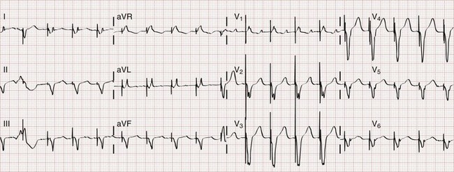
Biventricular pacing can usually be recognized on the standard ECG (Fig. 80-9). Two stimulus artifacts or “spikes” may be seen preceding a paced QRS complex. With biventricular pacing, a predominantly negative QRS complex is seen in lead I, in contrast to the typical upright complex seen with right ventricular pacing (see Fig. 80-2). A predominantly positive QRS complex is seen in lead V1 with biventricular pacing.28
Left Ventricular Assist Devices
Mechanical ventricular assistance devices have been used as a “bridge” to transplantation since the 1960s.29 These implanted devices replace or support the pump function of the left ventricle and were originally bulky and mechanically complex owing to the pulsatile nature of the pump mechanisms. This usually resulted in extended in-hospital care while the patient awaited cardiac transplantation. Newer devices, such as the Jarvik 2000 and HeartMate II, are continuous flow pumps that are portable and powered with a comparatively smaller battery pack. Implantation is associated with fewer infectious complications and lower immediate postoperative mortality, and survival for more than 1 year is increasingly common. The greatest mortality is noted within the first 30 days after implantation and during hospitalization. Left ventricular assistance devices (LVADs) are commonly used as “destination” therapy in patients who do not qualify for cardiac transplantation.29,30
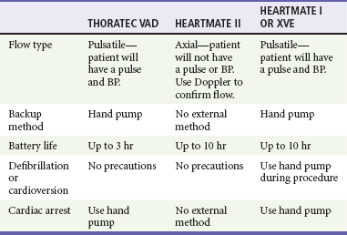
Patients with an LVAD typically require care at cardiac transplant centers. As technology progresses, emergency physicians not based at a transplant center may encounter a patient with an LVAD. In such cases, telephone consultation with an expert at a transplant center may help avoid missteps. The more common complications with this device include infection and embolic stroke. Device failure usually results in severe heart failure. If necessary, dopamine, dobutamine, or a combination of these drugs may be given to treat congestive heart failure symptoms while the patient awaits transfer. If cardiac arrest occurs, chest compressions may dislodge the device. The hand pump should be used to provide circulation if this backup method is available and early transition to cardiopulmonary bypass should be considered (Table 80-3).
Key Concepts
 Pacemaker malfunction soon after implantation (within 6-8 weeks) is usually a result of a lead problem, such as a lead displacement, or a pacemaker programming failure, such as a pacing rate too slow for the patient’s needs.

 With lithium-iodine batteries, abrupt failure is an unlikely cause of pacemaker malfunction.


References
1. Beck, H, et al. 50th anniversary of the first successful permanent pacemaker implantation in the United States: Historical review and future directions. Am J Cardiol. 2010;106:810.
2. Passman, R, Kadish, A. Sudden death prevention with implantable devices. Circulation. 2007;116:561.
3. Birnie, D, et al. Reasons for escalating pacemaker implants. Am J Cardiol. 2006;98:93–97.
4. Ramani, GV, Uber, PA, Mehra, MR. Chronic heart failure: Contemporary diagnosis and treatment. Mayo Clin Proc. 2010;85:180.
5. Tang, AS, et al. Cardiac-resynchronization therapy for mild-to-moderate heart failure. N Engl J Med. 2010;363:2385.
6. Al-Majed, NS, McAlister, FA, Bakal, JA, Ezekowitz, JA. Meta-analysis: Cardiac resynchronization therapy for patients with less symptomatic heart failure. Ann Intern Med. 2011;154:401.
7. Zipes, DP, et al. ACC/AHA/ESC 2006 guidelines for management of patients with ventricular arrhythmias and the prevention of sudden cardiac death: A report of the American College of Cardiology/American Heart Association Task Force and the European Society of Cardiology Committee for Practice Guidelines (writing committee to develop Guidelines for Management of Patients with Ventricular Arrhythmias and the Prevention of Sudden Cardiac Death): Developed in collaboration with the European Heart Rhythm Association and the Heart Rhythm Society. Circulation. 2006;114:e385.
8. Packer, DL, et al. ICDs: Evidence, guidelines, and glitches. Heart Rhythm. 2011;8:800.
9. Maisel, WH. Safety issues involving medical devices: Implications of recent implantable cardioverter-defibrillator malfunctions. JAMA. 2005;294:955.
10. Epstein, AE, et al. ACC/AHA/HRS 2008 Guidelines for Device-Based Therapy of Cardiac Rhythm Abnormalities: A report of the American College of Cardiology/American Heart Association Task Force on Practice Guidelines (Writing Committee to Revise the ACC/AHA/NASPE 2002 Guideline Update for Implantation of Cardiac Pacemakers and Antiarrhythmia Devices) developed in collaboration with the American Association for Thoracic Surgery and Society of Thoracic Surgeons. J Am Coll Cardiol. 2008;51:e1.
11. Bernstein, AD, et al. The revised NASPE/BPEG generic code for antibradycardia, adaptive-rate, and multisite pacing. Pacing Clin Electrophysiol. 2002;25:260.
12. Kaszala, K, Huizar, JF, Ellenbogen, KA. Contemporary pacemakers: What the primary care physician needs to know. Mayo Clin Proc. 2008;83:1170.
13. Maisel, WH, et al. Pacemaker and ICD generator malfunction: Analysis of Food and Drug Administration annual reports. JAMA. 2006;295:1901.
14. Kusumoto, FM, Goldschlager, N. Device therapy for cardiac arrhythmias. JAMA. 2002;287:1848.
15. Baddour, LM, et al. Update on cardiovascular implantable electronic device infections and their management. A scientific statement from the American Heart Association. Circulation. 2010;121:458.
16. Kucher, N. Deep-vein thrombosis of the upper extremities. N Engl J Med. 2011;364:861.
17. McMullan, J, et al. Care of the pacemaker/implantable cardioverter defibrillator patient in the ED. Am J Emerg Med. 2007;25:812.
18. Dretzke, J, et al. Dual chamber versus single chamber ventricular pacemakers for sick sinus syndrome and atrioventricular block. Cochrane Database Syst Rev. (2):2004.
19. Tops, LF, Schalij, MJ, Bax, JJ. The effects of right ventricular apical pacing on ventricular function and dyssynchrony. J Am Coll Cardiol. 2009;54:764.
20. Goldschlager, N, et al. Environmental and drug effects on patients with pacemakers and implantable cardioverter/defibrillators: A practical guide to patient treatment. Arch Intern Med. 2001;161:649.
21. Shah, PM, Ellenbogen, KA. Life after pacemaker implantation: Management of common problems and environmental interactions. Cardiol Rev. 2001;9:193.
22. Barold, SS, Leonelli, F, Khan, N, Cutro, R, Herweg, B. Pacemaker tachycardia: Is it pacemaker-mediated tachycardia or sinus tachycardia? Pacing Clin Electrophysiol. 2007;30:256.
23. Stevenson, WG, et al. Clinical assessment and management of patients with implanted cardioverter-defibrillators presenting to nonelectrophysiologists. Circulation. 2004;110:3866.
24. Gehi, AK, Mehta, D, Gomes, JA. Evaluation and management of patients after implantable cardioverter-defibrillator shock. JAMA. 2006;296:2839.
25. Swerdlow, CD, Friedman, PA. Advanced ICD troubleshooting. Part II. Pacing Clin Electrophysiol. 2006;29:70.
26. Jarcho, JA. Biventricular pacing. N Engl J Med. 2006;355:288.
27. Cubbon, RM, Witte, KKA. Cardiac resynchronization therapy for chronic heart failure. BMJ. 2009;338:1064.
28. Burkhardt, JD, Wilkoff, BL. Interventional electrophysiology and cardiac resynchronization therapy. Delivering electrical therapies for heart failure. Circulation. 2007;115:2208.
29. Boilson, BA, Raichlin, E, Park, SJ, Kushwaha, SS. Device therapy and cardiac transplantation for end-stage heart failure. Curr Probl Cardiol. 2010;35:8.
30. Starling, RC, et al. Results of the post–U.S. Food and Drug Administration–approval study with a continuous flow left ventricular assist device as a bridge to heart transplantation: A prospective study using the INTERMACS (Interagency Registry for Mechanically Assisted Circulatory Support). J Am Coll Cardiol. 2011;57:1890.
[/level-membership-for-emergency-medicine-category][not-level-membership-for-emergency-medicine-category]Chapter 80
Implantable Cardiac Devices
Perspective
Electrical cardiac pacing for the management of bradyarrhythmias was first described in 1952, and permanent transvenous pacing devices were introduced into clinical practice in the early 1960s.1 The first devices for endocardial defibrillation were implanted in surviving victims of sudden cardiac death in 1980.2 Implanted electrical devices for the management of cardiac dysrhythmias have changed rapidly over the years, with both increasing complexity and miniaturization. Survey data from 2002 indicated that approximately 612 new pacemakers per million population were implanted in the United States.3 Indications for the use of permanent pacemakers in the management of congenital and acquired heart disease include cardiac resynchronization therapy for heart failure.4–6
A number of large clinical trials comparing implantable cardioverter-defibrillators (ICDs) with antiarrhythmic drugs for the prevention of sudden cardiac death resulting from ventricular dysrhythmias have indicated that ICDs significantly improve survival.7,8 Such studies have led to a dramatic increase in ICD implantations, and it is estimated that there are more than 125,000 new ICD implants annually in the United States.9 The widespread use of these devices ensures that the emergency physician frequently encounters such patients, often with symptoms that may be related to malfunction of the pacemaker or ICD.
Indications for Permanent Pacemakers and Antiarrhythmia Devices
Guidelines for the implantation of these devices have been developed by a joint task force of the American Heart Association (AHA) and the American College of Cardiology (ACC) and are periodically updated.10 With use of an evidence-based approach, recommendations are categorized as class I, II, or III. Class I includes conditions for which there is general agreement that a device should be implanted. A class II recommendation includes conditions for which these devices are frequently used but for which there is disagreement about their need or benefit. Class III is reserved for conditions for which there is general agreement that a device is not needed.
In the case of pacemaker therapy, additional factors are considered when selecting the mode of pacing and include, but are not limited to, overall health, lifestyle, and occupation of the patient. Class I indications for a permanent pacemaker or ICD are listed in Boxes 80-1 and 80-2. In general, pacing is recommended for patients with symptomatic heart block, symptomatic sinus bradycardia, and atrial fibrillation with a symptomatic bradycardia (low ventricular response rate) in the absence of medications that affect atrioventricular (AV) conduction. Controversial indications include pacing in patients with syncope, heart block, or fatigue in the presence of some conduction disease or bradycardia. The likelihood of a patient’s improvement after pacing can be assumed only if the symptoms can be closely correlated with inadequate rate.
Pacemaker Terminology
A letter code, initially established in 1974 and revised as technology advances, standardizes nomenclature for pacemakers.11 Table 80-1 includes an explanation of the five-letter code scheme and the standard abbreviations in each category. The first three code letters are used most commonly. Using this table, one should be able to understand the features of any pacing mode. For example, a VDD pacemaker is capable of pacing only the ventricle, sensing both atrial and ventricular intrinsic depolarization, and responding by dual inhibition of both atrial and ventricular pacing if intrinsic ventricular depolarization occurs; a paced ventricular beat is triggered in response to a sensed intrinsic atrial depolarization. The codes of a permanent pacemaker that are used most frequently and the indications, advantages, and disadvantages of each are listed in Table 80-2. Detailed algorithms for matching a patient with a pacemaker exist.10 The majority of permanent pacemakers are dual chamber and often rate adaptive.12
Table 80-1
*In the triggered response mode, the pacemaker discharges or fires when it recognizes an intrinsic depolarization. As a result, pacemaker spikes occur during inscription of the QRS complex. Because this mode results in high energy consumption and a shortened battery life and because the sensing response can be misinterpreted as pacemaker malfunction, this sensing mode is not used with modern pacemakers.
Pacemaker Components
Permanent pacemakers have endocardial leads that are positioned in contact with the endocardium of the right ventricle and, in the case of a dual-chamber device, the right atrium, with a subclavian or cephalic vein approach used for insertion. Occasionally, an epicardial lead may be implanted during open-heart surgery performed for another indication, such as prosthetic valve insertion or correction of a congenital cardiac defect. Pacemaker leads, like power sources, continue to undergo major technical improvements.1 Innovations include resilient plastic insulation surrounding the electrodes that reduces the chance of complete lead disruption or breakage (resulting in failure to pace or sense) and the chance of partial fracture (resulting in a “make or break” contact with intermittent failure to sense or pace). Despite these advances, problems with the electrical circuitry remain the most common cause of pacemaker malfunction.13 A lead capable of active fixation is more commonly used in patients with cardiomyopathies and right ventricular dilation complicated by tricuspid regurgitation.
Pacemaker leads may be either bipolar or unipolar in configuration. A bipolar endocardial lead has both the negative (distal) and the positive (proximal) electrodes, separated by approximately 1 cm, within the heart. A unipolar lead has the negative electrode in contact with the endocardial surface, and the positive pole is the metallic casing of the pulse generator. Each lead system has potential advantages and disadvantages.1 The unipolar configuration is not compatible with ICD systems and is prone to oversensing of myopotentials and electromagnetic interference but is of smaller diameter and less susceptible to fracture. The bipolar configuration is compatible with ICD systems but is larger and more prone to lead fractures. Oversensing, however, is rarely a problem. The selection of lead configuration usually depends on the experience and preference of the operator.
The Standard Electrocardiogram during Normal Cardiac Pacing
The modern pacemaker has two basic functions: to stimulate the heart electrically and to sense intrinsic cardiac electrical activity. Additional functions are available and are noted in the pacemaker code system (see Table 80-1, letters 4 and 5). The pacemaker delivers an electrical stimulus to either the atrium or the ventricle if it does not recognize (sense) any intrinsic electrical activity from that chamber after a selected time interval. This interval is usually programmed at the time of implantation and can be changed noninvasively at a later time, if necessary, with use of a programming and “interrogating” device provided by the pacemaker manufacturer. If the pacemaker recognizes or senses an intrinsic atrial depolarization (P wave) or ventricular depolarization (QRS complex), it inhibits or resets its output to prevent competition with the underlying intrinsic rhythm. The stimulus intensity and sensing threshold (amplitude of electrical activity that is detected as being intrinsic) are typically set at the time of implantation but can also be reprogrammed later.
The two basic functions of a pacemaker can be easily recognized and confirmed on a standard 12-lead electrocardiogram (ECG) or rhythm strip. The normal function of a single-chamber VVI pacemaker is most easily recognized (Fig. 80-1). After a programmed interval is surpassed during which intrinsic ventricular activity does not occur, a pacer “spike” or stimulus artifact appears. The pacer spike is a narrow deflection that is usually less than 5 mm in amplitude with a bipolar lead configuration and usually 20 mm or more in amplitude with a unipolar lead. A wide QRS complex appears immediately after the stimulus artifact. Depolarization begins in the right ventricular apex, and the spread of excitation does not follow normal conduction pathways. Characteristically, a left bundle branch block conduction pattern is seen. A right bundle branch pattern is abnormal and suggests lead displacement. In VVI pacing the paced QRS complexes are independent of intrinsic atrial depolarization if present (AV dissociation).
The recognition of normal dual-chamber pacing is more complex owing to the interactive sensing and pacing of the right atrium and ventricle (Fig. 80-2).14 Pacing intervals are preprogrammed, may be changed noninvasively at a later time, and are generally specific to the patient’s needs. Pacing rates and delay intervals typically vary from patient to patient. Dual-chamber devices are typically used in patients with nonfibrillating atria coupled with intact AV conduction. A normal-appearing QRS complex may follow an intrinsic “P” wave as a result of normal sinoatrial node discharge if the intrinsic atrial depolarization is conducted to the ventricles. The intrinsic p wave and QRS complex inhibit the atrial and ventricular circuitry. A normal QRS complex follows a paced p wave if the paced atrial beat is conducted through the AV node and the programmed AV delay period is not exceeded. If it is not conducted to the ventricles (AV delay period exceeded), the pacemaker stimulates the ventricle, resulting in a paced p wave and a wide, paced QRS complex with left bundle branch block configuration.
Recognition of the interactivity of the paced chambers is important. A paced p wave may be mistaken for failure to sense or pace, and malfunction may be diagnosed when it is not present (pseudomalfunction). In addition, if the programmed rate of the pacemaker approximates the patient’s intrinsic heart rate, fusion of paced and native beats may occur and represents another common type of pseudomalfunction (Fig. 80-3).
Complications of Implantation
Pacemaker implantation is a surgical procedure and, like all surgery, carries a risk of infection; the presence of a foreign body enhances this risk. The incidence of infection is small—approximately 2% for wound and subcutaneous pacemaker “pocket” infection and approximately 1% for bacteremia with sepsis. The presence of a foreign body complicates management, and few cases of bacteremia that develop after implantation can be managed with antibiotics alone. In most instances, reimplantation and replacement of the lead system are necessary.15
When a local infection or bacteremia is suspected, blood cultures should be obtained and intravenous antibiotic therapy initiated. Staphylococcus aureus and Staphylococcus epidermidis are isolated in approximately 60 to 70% of cases. Empirical antibiotic therapy should include vancomycin pending culture and sensitivity data. If blood cultures are positive, the pulse generator and pacemaker lead are usually removed, temporary transvenous pacing is performed, and intravenous antibiotic therapy is continued for 4 to 6 weeks. The permanent pacemaker and lead are subsequently reimplanted.15
Thrombophlebitis
The incidence of venous obstruction associated with permanent transvenous pacemakers ranges from 30 to 50%, with approximately one third of patients having complete venous occlusion.16 Thrombosis of varying degrees can involve the axillary, subclavian, and innominate veins or the superior vena cava (SVC). The site of insertion does not appear to affect the incidence of this complication. Chronic thrombosis of the veins of the upper arm is common and usually asymptomatic owing to extensive venous collateral circulation.
The “Pacemaker Syndrome”
These symptoms are termed the pacemaker syndrome.17 The cause of this syndrome is the loss of AV synchrony and the presence of ventriculoatrial conduction, and it is most commonly encountered in the setting of VVI pacing. It is also described with the DDI mode. With VVI pacing, the ventricle is electrically stimulated and depolarized, resulting in ventricular systole. If sinus node function is intact, the atria can be depolarized by a sinus impulse and contract when the tricuspid and mitral valves are closed. This contractile asynchrony results in an increase in jugular and pulmonary venous pressures and may produce symptoms of congestive heart failure.
Approximately 20% of patients report symptoms suggesting the pacemaker syndrome after pacemaker insertion. In most instances, symptoms are mild and patients adapt to them. In approximately one third of these patients, symptoms are severe. Treatment usually requires replacing a VVI pacemaker with a dual-chamber pacemaker or lowering the pacing rate of the VVI unit. If symptoms occur in a patient paced in the DDI mode, optimizing the timing of atrial and ventricular pacing is usually required. Patients appear to prefer dual-chamber pacing to the VVI modality.18 Persistence or worsening of symptoms of congestive heart failure may also be caused by the altered ventricular activation sequence inherent with stimulation of the right ventricle.19 Biventricular pacing may be required in selected patients.
[/not-level-membership-for-emergency-medicine-category]
