[level-membership-for-radiology-category]
Implant assessment
Introduction
• Endosteal – placed in the bone. These are manufactured in a variety of shapes – screw, smooth-sided or plate-form, and essentially replace the roots of one or more teeth
• Subperiosteal – placed on the bone, under the periosteum and secured in place with screws.
This chapter concentrates on endosteal dental implants which are more commonly used, particularly since P. I. Brånemark’s clinical research on the concept of osseointegration which he defined as a direct connection between living bone and a load carrying endosseous implant at the light microscopic level. There are many different endosteal implant systems available, and it is beyond the scope of this book to discuss all the systems and their various advantages and disadvantages. The Brånemark system, described here, is probably the best known and has been researched over the longest period demonstrating acceptable 20-year success rates. Most currently used implant systems can be viewed as design modifications to this basic concept.
The Brånemark system
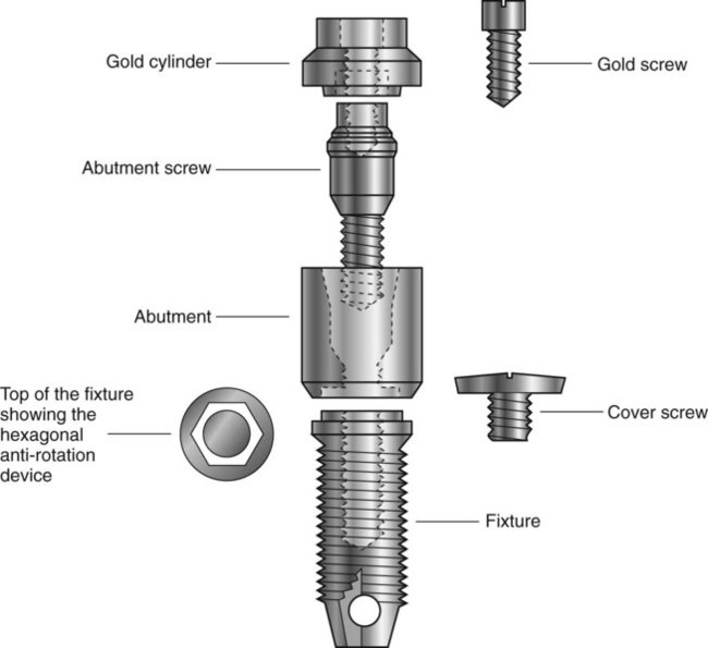
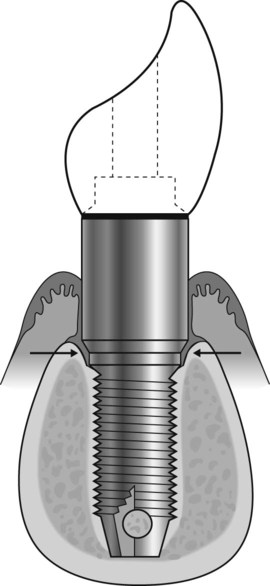
Treatment usually involves either a two-stage or a one-stage (non-submerged) surgical procedure followed by the restorative phase. Initially, in the two-stage technique the fixture is placed in vital bone ensuring a precision fit. The cover screw is screwed into the top of the fixture to prevent downgrowth of soft and hard tissue into the internal threaded area. The fixture is then left buried beneath the mucosa for 3–6 months. (It is important during this initial healing period to avoid loading the fixture although early loading protocols are being used in certain clinical circumstances.) The fixture is then surgically uncovered, the cover screw removed and the abutment (the transmucosal component) connected to the fixture by the abutment screw. An hexagonal anti-rotation device is incorporated into the top of the fixture. The gold cylinder, an integral part of the final restorative prosthesis, is finally connected to the abutment by the gold screw. A standard Brånemark implant is illustrated in Fig. 23.1.
Main indications
Replacement of missing teeth in patients with:
• Healthy dentitions which have suffered tooth loss because of trauma
• Developmentally missing teeth
• Remaining teeth not suitable as bridge abutments
• Severe ridge resorption making the wearing of dentures difficult
• Cleft palate and insufficient remaining teeth to support a denture/obturator
Treatment planning considerations
Clinical examination
• The patient’s age, general health and motivation
• The condition and position of the remaining teeth (if present), including their occlusion
• The status of the periodontal tissues and the level of oral hygiene
• The condition – quality and quantity – of the edentulous mandibular or maxillary alveolar bone
Radiographic examination
• The experience of the operator
• The thoroughness of the clinical examination, including the use of ridge-mapping techniques
• Panoramic radiography (see Fig. 23.2A)
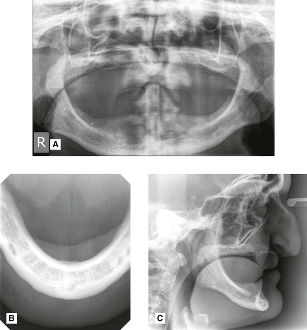
• Lower 90° occlusal radiography (see Fig. 23.2B)
• Lateral cephalometric radiography (see Fig. 23.2C)
• Cross-sectional linear tomography programmes available with some modern panoramic machines
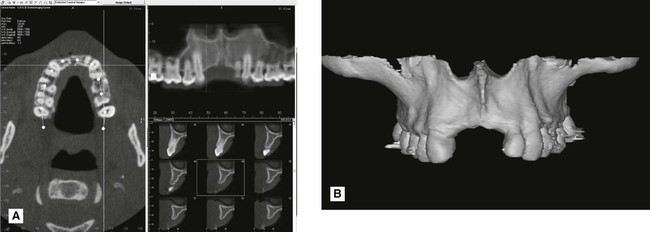
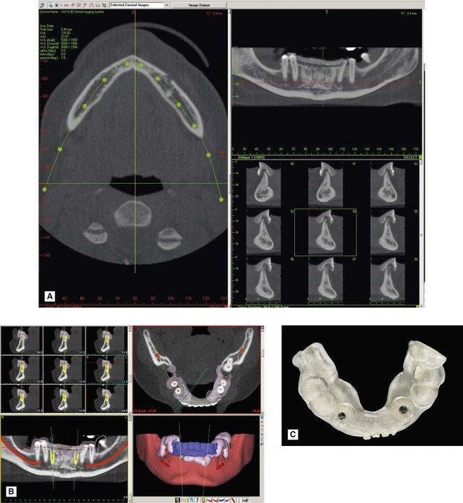
• Cone beam CT. This is ideal for implant assessment and is likely to become the imaging modality of choice when cross-sectional imaging is required (see Figs 23.3 and 23.4). Computer manipulation enables the production of panoramic and cross-sectional (transaxial) images. CBCT data can be imported into specially designed implant planning software programs, such as SimPlant® or NobelGuide®, to create 3-D reconstructions of the jaws and to plan the placement of implants in three dimensions. The software can also be used to design a drill guide so that the implant fixtures can be placed accurately at the proposed sites (see Fig. 23.4).
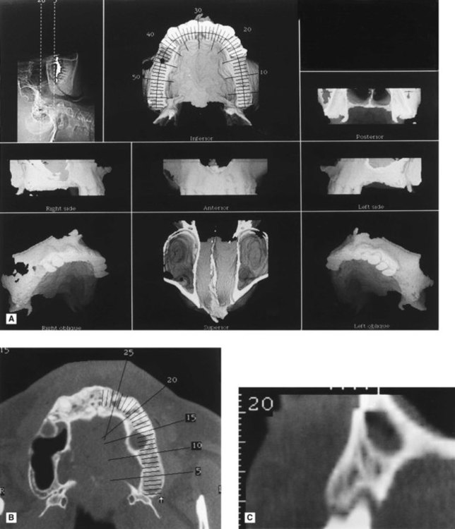
• Computed tomography (CT). Specific dental computer programs, designed for implant planning, have been written that are compatible with medical CT. This usually involves about 30 axial scans per jaw, each 1.5 mm thick. This information can then undergo computer manipulation to produce reformatted cross-sectional, panoramic and three-dimensional reconstructed images as shown in Fig. 23.5. The CT data can also be imported into implant planning software.
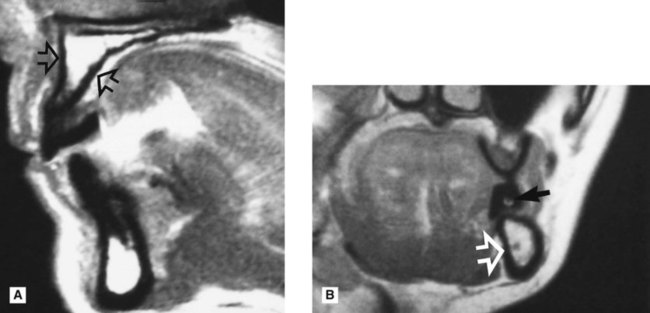
• Magnetic resonance (MR). This offers the advantages of not using ionizing radiation and producing sections in any desired plane without reformatting, as shown in Fig. 23.6.
Radiographic information provided
These various radiographic investigations are used to show:
• The position and size of relevant normal anatomical structures, including the:
• The shape and size of the antra, including the position of the antral floor and its relationship to adjacent teeth
• The presence of any underlying disease
• The presence of any retained roots or buried teeth
• The quantity of alveolar crest/basal bone, allowing direct measurements of the height, width and shape
Important points to note
• Cross-sectional imaging is important to provide information on the width and quality of the alveolar bone and the location of anatomical structures. The choice of imaging modality will obviously depend on the availability of facilities. The more complex the clinical case, the more comprehensive the radiographic assessment needs to be.
• Plastic stents containing radiopaque markers are often required for accurate localization of cross-sectional images. Gadolinium markers are used with MR (see Fig. 23.6).
• Radiation dose from medical CT imaging is typically higher than from cone beam CT.
• CT and cone beam CT data can be imported into specially designed implant planning software as described earlier.
Postoperative evaluation and follow-up
Criteria for success
1. That an individual, unattached implant is immobile when tested clinically.
2. That a radiograph does not demonstrate any evidence of peri-implant radiolucency.
3. That vertical bone loss be less than 0.2 mm annually following the implant’s first year of service.
4. That individual implant performance be characterized by an absence of signs and symptoms such as pain, infection, neuropathies, paraesthesia or violation of the inferior dental canal.
5. That, in the context of the above, a success rate of 85% at the end of a 10-year period be the minimum criteria for success.
Radiographic evaluation (see Figs 23.7–23.9)
Radiographs allow evaluation of criteria 2 and 3, but also are used to assess:
 region immediately after surgery showing the buccopalatal position and angulation of the implant.
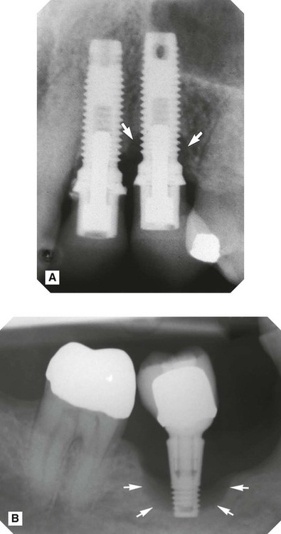 />
/>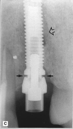
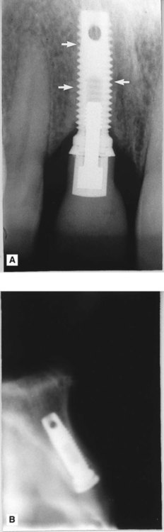
 , but virtually no bone loss around the implant replacing
  . B Periapical showing unsuccessful osseointegration. Note the radiolucency surrounding the implant (arrowed). C Periapical showing incorrect seating of the abutment on the fixture (solid arrows) and residual radiolucency from previous periapical area (open arrow).
 • The position of the fixture in the bone and its relation to nearby anatomical structures
• Healing and integration of the fixture in the bone
• The peri-implant bone level and any subsequent vertical bone loss – threaded fixtures allow easy measurement if radiographs are geometrically accurate
• Development of any associated disease, e.g. perimplantitis
• The fit of the abutment to the fixture
[/level-membership-for-radiology-category][not-level-membership-for-radiology-category]
Implant assessment
Introduction
• Endosteal – placed in the bone. These are manufactured in a variety of shapes – screw, smooth-sided or plate-form, and essentially replace the roots of one or more teeth
• Subperiosteal – placed on the bone, under the periosteum and secured in place with screws.
This chapter concentrates on endosteal dental implants which are more commonly used, particularly since P. I. Brånemark’s clinical research on the concept of osseointegration which he defined as a direct connection between living bone and a load carrying endosseous implant at the light microscopic level. There are many different endosteal implant systems available, and it is beyond the scope of this book to discuss all the systems and their various advantages and disadvantages. The Brånemark system, described here, is probably the best known and has been researched over the longest period demonstrating acceptable 20-year success rates. Most currently used implant systems can be viewed as design modifications to this basic concept.
The Brånemark system
Treatment usually involves either a two-stage or a one-stage (non-submerged) surgical procedure followed by the restorative phase. Initially, in the two-stage technique the fixture is placed in vital bone ensuring a precision fit. The cover screw is screwed into the top of the fixture to prevent downgrowth of soft and hard tissue into the internal threaded area. The fixture is then left buried beneath the mucosa for 3–6 months. (It is important during this initial healing period to avoid loading the fixture although early loading protocols are being used in certain clinical circumstances.) The fixture is then surgically uncovered, the cover screw removed and the abutment (the transmucosal component) connected to the fixture by the abutment screw. An hexagonal anti-rotation device is incorporated into the top of the fixture. The gold cylinder, an integral part of the final restorative prosthesis, is finally connected to the abutment by the gold screw. A standard Brånemark implant is illustrated in Fig. 23.1.
Main indications
Replacement of missing teeth in patients with:
• Healthy dentitions which have suffered tooth loss because of trauma
• Developmentally missing teeth
• Remaining teeth not suitable as bridge abutments
• Severe ridge resorption making the wearing of dentures difficult
• Cleft palate and insufficient remaining teeth to support a denture/obturator
Treatment planning considerations
Clinical examination
• The patient’s age, general health and motivation
• The condition and position of the remaining teeth (if present), including their occlusion
• The status of the periodontal tissues and the level of oral hygiene
• The condition – quality and quantity – of the edentulous mandibular or maxillary alveolar bone
