27 Imaging of Implantable Devices
 Radiography
Radiographs provide essential information about the location, type, and integrity of the pulse generators and leads of both pacing and defibrillation systems. X-ray films also provide basic details of patient anatomy. Interpretation of a chest radiograph should be focused and systematic, with examination of the bony structures, cardiac silhouette, lung fields, trachea, and aorta as well as the presence and location of all preexisting hardware, prosthetic valves, and valve rings or calcification (Fig. 27-1). Abdominal radiographs should be obtained when abdominal device implantation is anticipated.
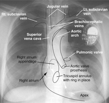
Figure 27-1 Overlay of diagram on posteroanterior chest radiograph.
(From Castle LW, Cook S: Pacemaker radiography. In Ellenbogen KA, Kay GN, Wilkoff BL, editors: Clinical cardiac pacing. Philadelphia, 1995, Saunders, p 538.)
Preprocedural Chest Radiography
Pacemaker/ICD Pulse Generators and Implantable Loop Recorders
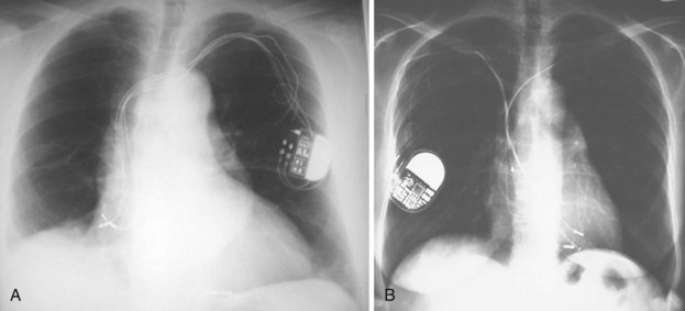
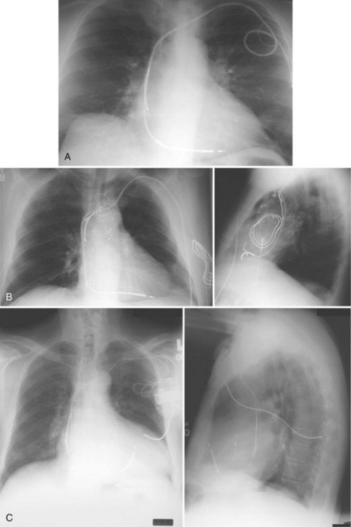
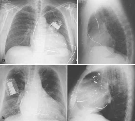
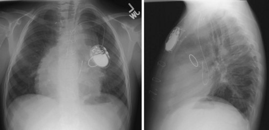
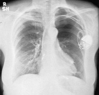
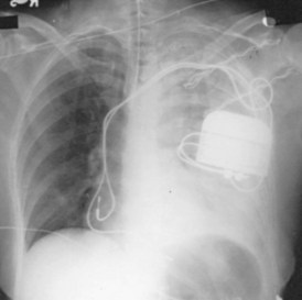
For transvenous systems, the pulse generator is typically located in the subcutaneous, prepectoral region caudal to the clavicle, overlying the pectoralis major muscle. In some patients, the device is located in a subpectoral or submammary position (Fig. 27-2). In pediatric patients and patients with older, larger ICD pulse generators or epicardial ICD lead systems, devices may be located in the abdomen, typically in the left upper quadrant and occasionally in the right upper quadrant or epigastrium (Fig. 27-3). Although most pulse generators are implanted in the subcutaneous region in adult patients, many have been implanted below the rectus abdominis muscle in children and younger women. The pulse generator is also generally implanted abdominally in patients in whom a femoral vein approach is required (Fig. 27-4).
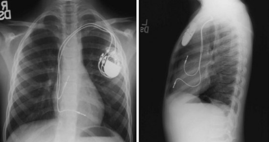
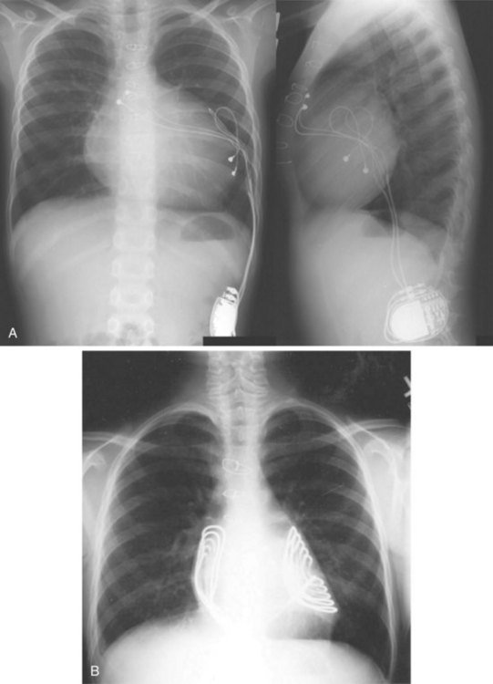
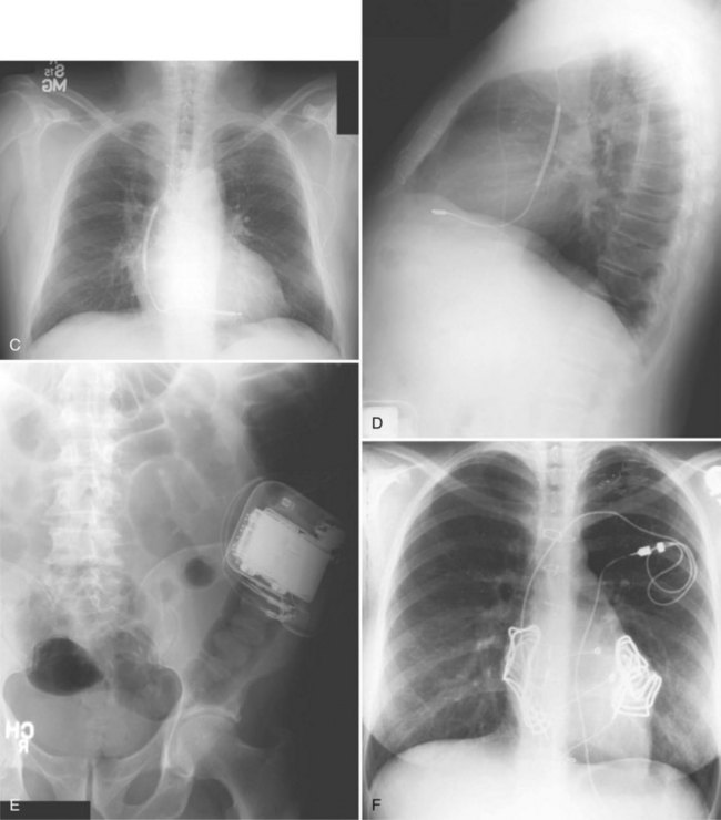
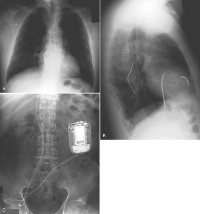
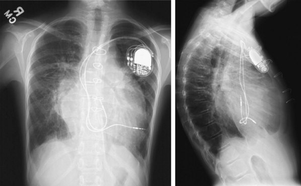
Figure 27-4 Implantable cardioverter-defibrillator with defibrillation leads, including azygos coil lead.
The generator manufacturer and type can be identified from radiography. Most pacemaker and ICD pulse generators have a radiopaque code or logo identifying the manufacturer and model of the device (Figs. 27-5 and 27-6). If the manufacturer can be determined, the proper programmer can be selected. Most current manufacturer programmers can “auto-identify” the specific devices of that manufacturer. Manufacturer technical support divisions may be able to aid in identification of lead systems and devices and can often access device data, such as leads implanted, pacing or shocking configurations, and implant thresholds. Some patients may have both pacing and ICD systems, as well as leads or devices that originate from different manufacturers. Figure 27-7 shows the appearance of implantable loop recorders.
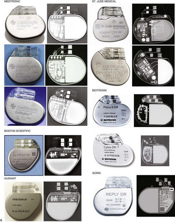
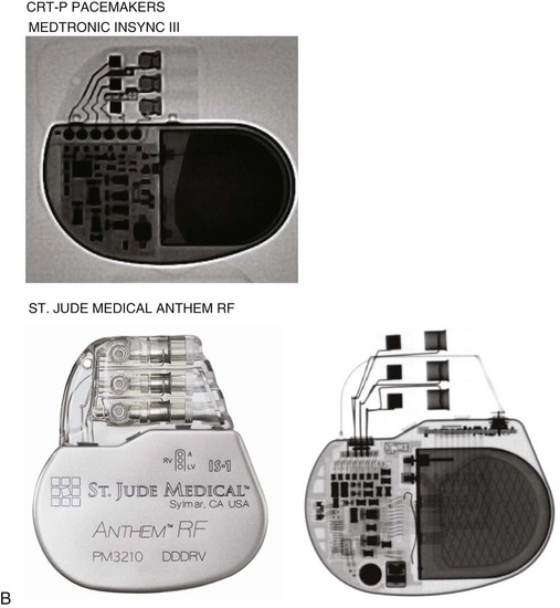
Figure 27-5 Pacing pulse generators and radiographic appearance.
(Courtesy Medtronic, Minneapolis; St. Jude Medical, St. Paul, Minn; Guidant, Boston Scientific, Natick, Mass; Biotronik, Berlin; and ELA/Sorin, Milan.)

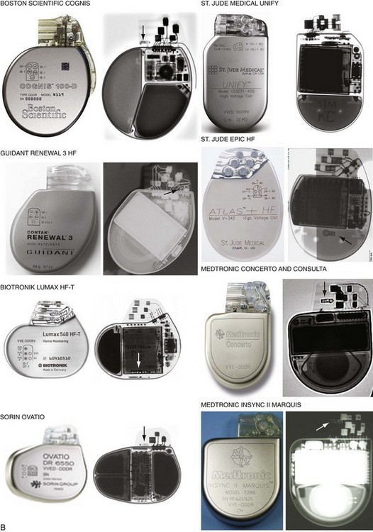
Figure 27-6 Implantable cardioverter-defibrillator (ICD) pulse generators and radiographic appearance.
(Courtesy Guidant, Boston Scientific, Natick, Mass; St. Jude Medical, St. Paul, Minn; Medtronic, Minneapolis; Biotronik, Berlin; and ELA/Sorin, Milan.)
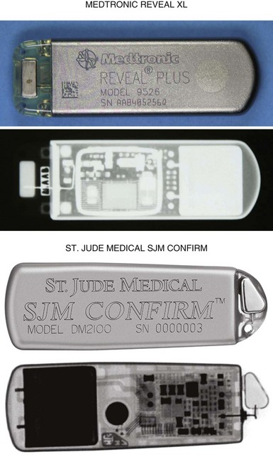
Figure 27-7 Implantable loop recorders.
(Courtesy Medtronic, Minneapolis, and St. Jude Medical, St. Paul, Minn.)
The pacemaker or ICD connector block should be carefully examined radiographically. The connector pins should be advanced beyond the distal pin set-screw blocks (Fig. 27-8). It is usually difficult to determine radiographically whether set screws are in contact with the electrodes. Clues to the polarity of pacing pulse generators include the number and type of connector pins. Determining the type of connector pins (International Standard 1 [IS-1], 3.2-mm Voluntary Standard [VS]-1, 5- or 6-mm, or the new IS-4 connectors) before device replacement avoids an intraoperative discovery that a compatible device is not readily available for the exchange. Radiographically, detection of connector pins that appear longer than the conventional IS-1 pins should prompt checking of lead connector type.
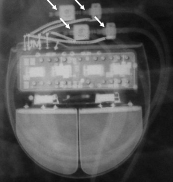
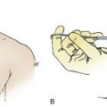
Figure 27-8 Examination of device for lead connector pin insertion into header.
Pins can be visualized extending past the distal connector blocks (arrows).
Migration of the pulse generator may be seen radiographically in older patients with loosened prepectoral fascia, patients who have lost significant amounts of weight, or with pulse generators implanted within larger areas of subcutaneous prepectoral fatty tissue.1
Pacing and Defibrillation Leads
When planning lead revision and/or extraction, one should assess the types, location, and integrity of all leads radiographically. Higher radiographic penetration may be required to more clearly demonstrate lead components. Dislodgment can be identified and is aided by comparison with old films. Leads generally do not have manufacturer-specific, characteristic radiopaque identifiers, but radiography may provide clues to the lead type (active or passive fixation; unipolar or bipolar) and integrity.2
Venous Anatomy for Localization of Lead Positions
Most pacemaker and ICD leads are inserted transvenously. The subclavian, axillary, and cephalic veins are most often used for lead insertion, with the internal or external jugular or femoral veins used rarely. The cephalic vein courses lateral to the biceps, continuing in a groove between the deltoid and pectoralis major muscles, then empties into the axillary vein (Fig. 27-9). The axillary vein drains the basilic and brachial veins, coursing medially over the lateral margin of the first rib to become the subclavian vein under the clavicle. This marks the usual site for insertion of pacemaker or defibrillator leads (see Fig. 27-1). A change in the directionality of the lead can sometimes indicate the location of the venous insertion site or suture tie-down sleeve. A more lateral insertion site suggests a cephalic or lateral axillary insertion site. Medial insertions into the subclavian vein should be inspected for evidence of lead crush injuries. Lateral axillary insertion sites should be examined for excessive angulation.
After entering the venous system, leads typically pass through the brachiocephalic veins, which are formed by the joining of the internal jugular and subclavian veins behind the head of the clavicle, to the superior vena cava (SVC), and then to the right atrium or right ventricle. In a small percentage of patients, a persistent left SVC is present and drains into the coronary sinus (see later).3
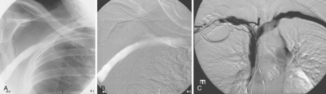
On preparation for a procedure requiring insertion of a new lead, peripheral subclavian and SVC venography can be helpful in anticipating the need for lead extraction or preparation of a new site for venous access because of venous occlusion or severe stenoses (Fig. 27-10). Chronic venous occlusion is often marked by the presence of venous collaterals.
The coronary sinus (CS), which enters the inferior septal region of the right atrium, just anterior and superior to the opening of the inferior vena cava, receives most of the venous drainage of the heart (see Coronary Sinus Lead Positions). The main CS traverses the atrioventricular (AV) groove between the left atrium and left ventricle. Tributaries include the middle cardiac vein; posterior ventricular branch; posterolateral, lateral, and anterolateral marginal branches; and great cardiac vein, which is the extension of the CS beyond the takeoff of the left atrial oblique vein of Marshall. When the vein of Marshall is not present, the valve of Vieussens is used to define the interface of the CS and great cardiac vein. The posterior, posterolateral, and lateral branches of the CS are typical targets for left ventricular or biventricular pacing in CRT devices (see Chapter 22).
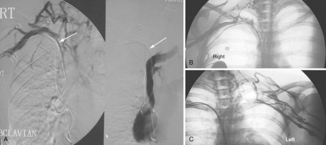
The azygos vein, which enters the posterior wall of the SVC, is sometimes the target vessel for ICD coil-lead implantation in patients with high defibrillation threshold (DFT), as the vessel travels posteriorly behind the heart, providing an additional favorable “shock vector” option4 (Fig. 27-11; see also Fig. 27-4).
Pacemaker Leads
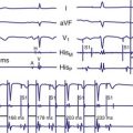
Besides identification of the venous and cardiac insertion sites of pacing leads, chest radiographs can help determine polarity and fixation types. A unipolar lead has a single electrode at the tip of the lead; a bipolar lead has two electrodes separated by a space. Active-fixation leads have screws that extend from the tip of the lead (Fig. 27-12, A). Passive-fixation leads have various types of tines that are radiolucent (cannot be visualized radiographically) (Fig. 27-12, B). Active-fixation leads may be fixed in the extended position or may have an extendable/retractable screw. Different manufacturers denote extension of the latter with various markers (Fig. 27-13).
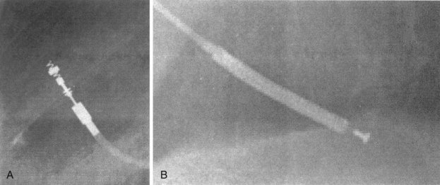
Figure 27-12 Radiographic appearance of transvenous leads.
A, Active-fixation, bipolar lead. B, Passive-fixation ICD lead.
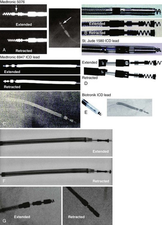
Figure 27-13 Active-fixation screw positions.
(Courtesy Medtronic, Minneapolis; St. Jude Medical, St. Paul, Minn; and Biotronik, Berlin.)
Atrial Lead Positions
In patients who have not undergone cardiac surgery, most atrial leads are fixed to the right atrial (RA) appendage and will exhibit a J shape with an anteriorly directed curve on the lateral view.5 Patients who have undergone cardiac surgery may not have suitable RA appendage remnants for fixation. Lead placement is generally guided by optimization of electrical characteristics, such as sensing and pacing thresholds and lead fixation stability. Leads may be implanted laterally, septally, caudally, or cranially in the right atrium, generally requiring active-fixation leads. Although most pacing systems use one atrial lead, pacing for atrial arrhythmia suppression may incorporate alternative-site or dual-site pacing.6,7 Placements targeting Bachmann’s bundle or the RA septum typically display lead tips directed near the high septum of the right atrium.8,9 The CS or septum near the CS may also be targeted; leads placed in the CS generally exhibit a large, open posterior curve. Higher posterior crossings on lateral films may suggest passage of the lead through a patent foramen ovale or atrial septal defect to the left atrium or ventricle.10
Ventricular Lead Positions
Ventricular pacing leads have traditionally been targeted to the right ventricular apex (RVA). The lead should display some slack, particularly as it traverses and is lifted by the tricuspid valve. The RVA is generally located to the left of the spine on the PA view with a slight inferior direction. On the lateral view, the lead is usually directed anteriorly (Fig. 27-14), unless the septal aspect of the apex is targeted. A more posterior course suggests positioning in the CS or middle cardiac vein. A large posterior curve suggests possible passage through a patent foramen ovale or atrial or ventricular septal defect to the left ventricle (Fig. 27-15).
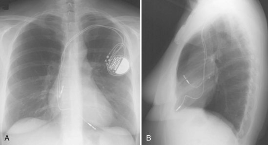
Figure 27-14 Ventricular pacing lead position in right ventricular apex and atrial lead in right atrial appendage.
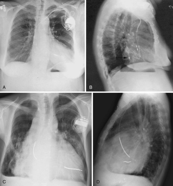
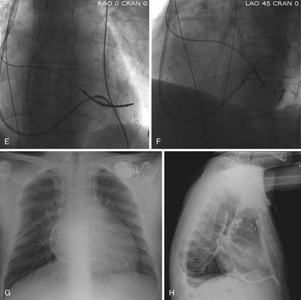
Figure 27-15 Abnormal lead placement into left ventricle.
(A and B from Trohman RG, Wilkoff B, Byrne T, Cook S: Successful percutaneous extraction of a chronic left ventricular pacing lead. Pacing Clin Electrophysiol 14:1448, 1991.)
Although the RVA has been the traditional site for ventricular pacing lead placement, awareness of the potential for left ventricular (LV) dyssynchrony from RVA pacing has led to more frequent use of right ventricular outflow tract (RVOT) or septal pacing11 (Fig. 27-16). A position away from the RVA may also be sought when there are high pacing thresholds at the apex or if an ICD lead is present at the apex, to avoid device-device interactions (Fig. 27-17). His bundle pacing has been proposed as an alternative to RVA pacing in the absence of infra-Hisian conduction system disease12 (Fig. 27-18). An extra set of bipolar sensing electrodes at the level of the right atrium on a ventricular lead body identifies a VDD single-lead pacing system, which is designed to sense in the atrium and allow atrial-synchronous ventricular pacing (Fig. 27-19).
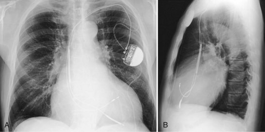
Figure 27-16 Ventricular pacing lead position in right ventricular outflow tract.
(Courtesy Walid Saliba, MD.)
Coronary Sinus Lead Positions
The branches of the CS are common targets for leads placed for LV or biventricular pacing for CRT.13 Placement of the CS lead involves localization and cannulation of the CS, CS venography, and placement of the lead in the target branch. Coronary sinus ostium (CS os) cannulation is accomplished using an angiographic approach or electrophysiologic approach. Angiographic technique involves the use of a variety of guiding sheaths and diagnostic catheters (described in Chapter 22) with boluses of contrast agent for locating the CS os. The EP technique involves the use of guiding sheaths with mapping catheters to help determine the presence of CS recordings on intracardiac electrograms.
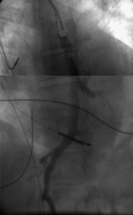
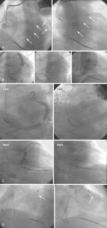
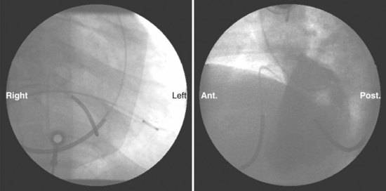
After gaining access to the CS, the outer guide sheath is advanced into the proximal portion of the CS at least 3 to 4 cm over a guidewire or a softer inner catheter to prevent mural dissection. Balloon occlusion with contrast venography can then identify potential target tributaries, strictures, and collateral vessels in selection of an optimal target vessel (Fig. 27-20). Balloon inflation must be performed with caution to avoid overinflation and dissection of the vein. After visualization of the distal vessels, the balloon is deflated to promote proximal runoff, allowing visualization of tributaries proximal to the balloon tip. Continued acquisition of images for a few extra seconds after contrast injection allows flow to tributaries through collaterals, which might highlight the posterior and posterolateral LV veins that could otherwise go unnoticed. Two radiographic planes are helpful for assessing the CS tributaries and ostia for optimal target vessel determination. The most common positions used are left anterior oblique (LAO) 25 to 45 degrees, AP, and right anterior oblique (RAO) 15 to 30 degrees.
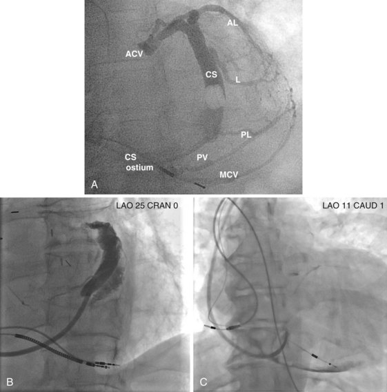
Coronary sinus anatomy is variable, and no consensus exists regarding the nomenclature of CS branch anatomy; as discussed earlier, however, common terminology is used, as depicted in Figure 27-20. From the CS ostium, the first branch is the middle cardiac vein (MCV), near which a posterior ventricular branch may enter. The distal CS becomes the great cardiac vein (GCV) after the takeoff of the vein of Marshall/valve of Vieussens. The GCV terminates at the takeoff of the anterior cardiac vein (ACV), which courses down the anterior interventricular groove. Between the MCV and ACV, posterior, posterolateral, lateral, anterolateral, and anteroseptal branches may be present. Using clock face positions as viewed in LAO projection, the CS os generally is located at 7 o’clock, the MCV at about 6 o’clock, the posterolateral veins at 5 o’clock to 2 o’clock, and GCV/ACV at 12 o’clock. If present, a persistent left SVC drains into the CS directly.14 Figure 27-21 illustrates typical lead tip positions.
Epicardial Lead Positions
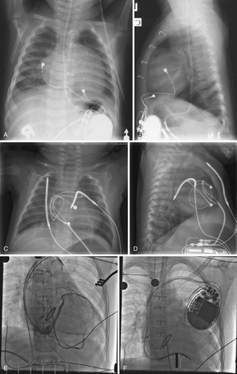
When placed for potential CRT, unipolar or bipolar leads are placed on the LV posterolateral free-wall epicardium either after failure to place transvenous CS leads or at concomitant valve or coronary bypass surgery (Fig. 27-22). Minimally invasive methods for implantation are available for patients not in need of concomitant cardiac surgery.15–17 Epicardial leads may also be placed in patients with congenital abnormalities or as part of cardiac surgical procedures with risk for or resulting in complete heart block (see Fig. 27-3) and in patients with prosthetic tricuspid valves (Fig. 27-23). In the past, epicardial leads had a higher incidence of malfunction than transvenous pacing leads, but newer lead designs may improve epicardial lead longevity. The leads are tunneled to the pulse generator pocket in either the pectoral or the abdominal area. Evaluation may require chest and abdominal radiographs, depending on the location of the pacemaker or ICD device, to allow examination of integrity of a lead throughout its entire course.
Identification of Possible Pacemaker Lead Malfunction
The presence of abandoned leads usually indicates that the leads were malfunctioning or were no longer needed. Examples of the latter situation are (1) permanent atrial fibrillation with change to a single-chamber from a dual-chamber pacemaker at device replacement and (2) upgrade from a permanent pacemaker to an ICD, abandoning and capping of the ventricular pacing lead and implanting an ICD lead. The proximal portion of the lead is usually capped, unattached to the generator, and free in the generator pocket. Some implanters cut the leads, but doing so risks retraction of a lead into the venous system, greatly increasing the difficulty of future extraction (Fig. 27-24, A). The implanter should determine whether the abandoned lead is present in its entirety or whether its proximal portion has been severed or retracted into the vein (Fig. 27-24, B).
Active-fixation leads have a radiopaque screw that may be fixed (extended) or retractable-extendable. The chest radiograph should be examined to determine whether the screw is extended properly, recognizing that there may be alternative markers to screw extension besides apparent extension past the tip electrode. Screw extension is marked by removal or creation of a space between radiopaque rings and by visualized extension of the screw past the tip (see Fig. 27-13, A).
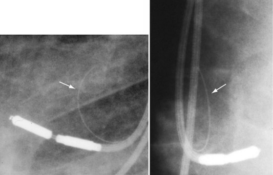
Particularly when troubleshooting device or lead malfunction before surgical exploration of a device system, the clinician must scrutinize the chest radiograph for lead integrity and connection to the device header, examining the header for any obvious disconnections. Often, the pin can be seen extending past the distal connector block (see Fig. 27-8). The lead coil should also be scrutinized for obvious discontinuity, abnormal angulation, and kinking, particularly between the pulse generator and the venous insertion site (Fig. 27-25). Medial venous insertion sites appear to be more prone to the subclavian clavicle-first-rib crush syndrome, or subclavian crush syndrome18,19 (Fig. 27-26). In addition, acute angulation of leads may lead to inner conductor fracture (Fig. 27-27). This situation may occur with insertions into the lateral axillary vein or with acute angulation out of the subclavian vein. Crimping of the lead insulation by tight ligatures around suture sleeves may cause the radiographic appearance of pseudofracture20,21 (Fig. 27-28). Pacing characteristics may be unaffected by such crimping, but over time, lead insulation damage or coil fracture may result and should be monitored. Another type of pseudofracture describes a transition from a coaxial to a linear configuration, such as in ICD leads at the transition from the coil to the cable, or where coils come together from a bifurcated (now obsolete) connector configuration.
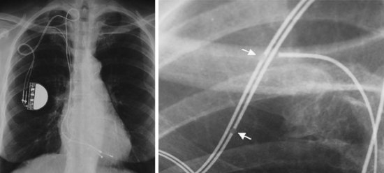
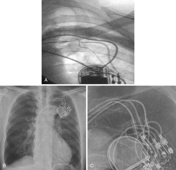
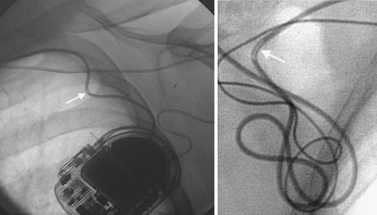
Figure 27-27 Conductor fracture.
Two examples of inner conductor fractures (arrows) caused by acute angulation of pacing leads.
(Courtesy Ludwig Binner, MD, University of Ulm, Germany.)
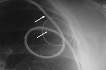
Excessive unintentional or intentional coiling and knotting of the leads may occur because of a large generator pocket or loose, fatty subcutaneous tissue, allowing rotation or repeated flipping of the pulse generator with physical activity or from patient manipulation, called twiddler’s syndrome or “reel syndrome”22,23 (Fig. 27-29). Chest radiography leads to diagnosis, and early identification of the problem with follow-up chest radiographs may help prevent its perpetuation. Such excessive coiling and knotting of the leads can lead to lead fracture, insulation breaks, or inappropriate defibrillator shocks.
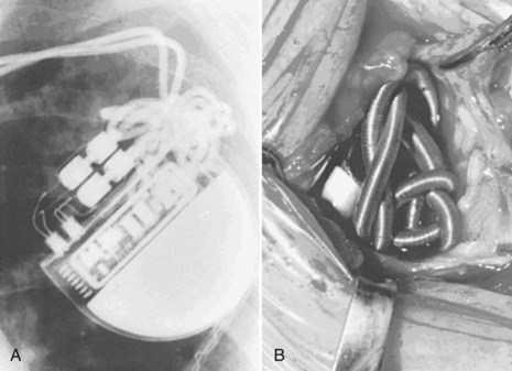
Figure 27-29 Twiddler’s syndrome.
(From Castle LW, Cook S: Pacemaker radiography. In Ellenbogen KA, Kay GN, Wilkoff BL, editors: Clinical cardiac pacing. Philadelphia, 1995, Saunders, p 560.)
A special situation in which radiographic imaging has been important has been for examination of the Telectronics Pacing Systems (Englewood, Colo.; now part of St. Jude Medical, Sylmar, Calif.) Accufix active-fixation and Encor passive-fixation atrial leads.24,25 Designed to maintain a J shape, these leads have retention wires located within the insulation in the Accufix lead and inside the coil in the Encor lead. The retention wire may fracture, protrude, and migrate, leading to cardiovascular perforation. Open J shapes appear more prone to fracture than more closed shapes. Coned-in views with higher penetration and digital fluoroscopy have been used to assess the retention wire (Fig. 27-30). The Encor lead appears less prone to fracture complications, but fracture is more difficult to detect. It has been associated with angulation in the interelectrode space. Chest radiographs and digital fluoroscopy with high magnification and multiple views should be used to optimize visualization of these retention wires.26
Implantable Cardioverter-Defibrillator Leads
The cornerstone of current ICD systems is a transvenous pace/sense-defibrillation lead placed into the right ventricle and typically connected to an “active-can” ICD pulse generator located in the prepectoral region, usually on the left side.27
These leads may have a single, high-voltage defibrillation coil, which should be situated in the right ventricle, or two high-voltage coils, the distal coil being positioned in the right ventricle, and the proximal coil positioned in the SVC–high RA area. The ventricular ICD lead tip is typically placed at the RVA with enough lead slack to allow a lift at the tricuspid valve. ICD leads may also be placed in the RVOT (Fig. 27-31). In patients with high DFT, a separate SVC coil lead may also be placed in the SVC-brachiocephalic region; alternately, a subcutaneous patch, coil, or array may be placed (Fig. 27-32). Subcutaneous electrodes are usually placed inferior and posterior to the axilla but may be placed in the left prepectoral region if the ICD is not an active-can device or if the ICD is located elsewhere (e.g., abdominal or right prepectoral region). Epicardial patch defibrillation leads (see Fig. 27-3, B and F) were placed using sternotomy or lateral thoracotomy in early ICD systems but rarely may still be required in patients who are not candidates for transvenous lead systems—because of absence of any venous vascular access, repeated infection with endocarditis, or tricuspid valve replacement, with some forms of congenital heart disease, and in small children.
Coronary sinus defibrillation leads were used in an early atrial defibrillator device but are not in current standard ICD systems. The atrial defibrillator device Metrix (InControl, Redmond, Wash.) used an S-shaped lead to maintain stability in the CS (Fig. 27-33). However, this lead is not currently being marketed, and other straight leads may be at a higher risk for dislodgment. Moreover, placement of defibrillation coil leads in the main CS may preclude future access of this venous system for CRT leads.
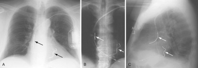
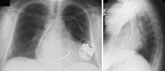
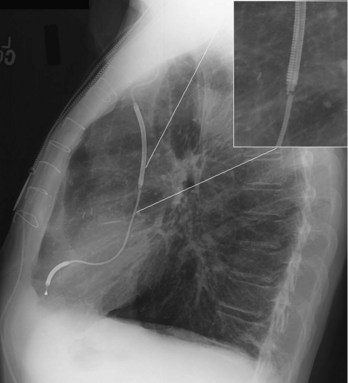
The azygos vein may be cannulated for placement of ICD defibrillation leads (Fig. 27-34; see also Fig. 27-11). The azygos enters the SVC posteriorly, just below the confluence of the brachiocephalic veins, and can provide access to a position posterior to the heart for optimization of the defibrillation vector. Similarly, an additional defibrillation lead/array can be placed in the subcutaneous tissue along the posterolateral wall to change the defibrillation vector in patients who cannot achieve a safe DFT through traditional dual-coil ICD leads.28
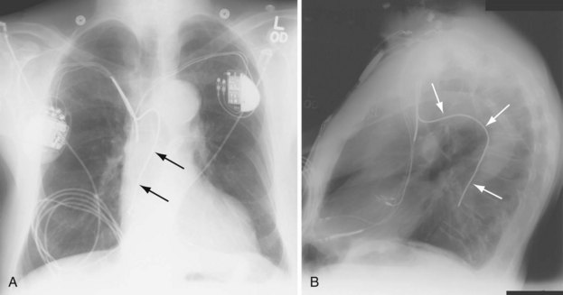
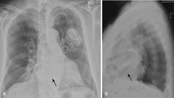
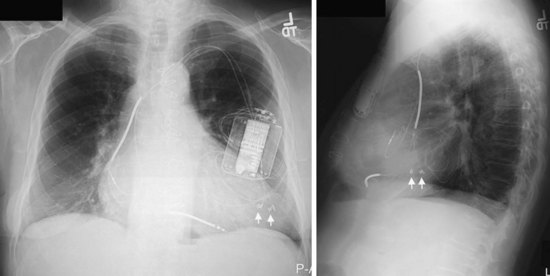
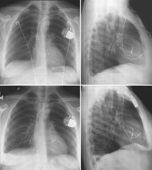
Figure 27-34 Azygos vein defibrillation lead.
Posteroanterior (A) and lateral (B) chest radiographs of patient in Figure 27-17 in whom high defibrillation thresholds required the addition of an azygos vein defibrillation coil (arrows). Note the posterior course from the superior vena cava.
Identification of Lead Malfunction
Although defibrillation lead diameters have become smaller, with some as small as pacing leads, most ICD leads have a larger diameter relative to pacing leads and thus may be more susceptible to subclavian crush syndrome. Chest radiographs should be inspected closely in the region near the venous insertion and suture sleeve tie-down sites. Leads, patches, coils, and arrays should be inspected for fracture and excessive bending or kinking. This inspection may require abdominal films and customized views. “Phantom fracture” and pseudofracture are used to describe a pseudo-discontinuity of one manufacturer’s ICD lead just distal to the proximal high-voltage coil29 (Fig. 27-35). This appearance is a normal feature of this particular lead. A discontinuity of radiopaque markers on the perimeter of some epicardial patches is likewise no cause for concern, because these markers are not a part of the defibrillation electrode and do not indicate lead fracture (see Fig. 27-32, E).
Special Considerations in Congenital Heart Disease
Congenital cardiovascular anomalies may result in unusual locations of pacing or ICD lead systems. An understanding of the native and corrected anatomy is essential for correct interpretation of radiographic imaging in patients with implanted devices. Epicardial pacing indications include residual intracardiac shunts, prosthetic pulmonary ventricular AV valves (usually tricuspid), severe right ventricular endocardial fibroelastosis, lack of viable access to the heart through systemic veins, and prohibitively small stature (Fig. 27-36). Thus, abdominal and chest radiographs should be obtained in patients with these diagnoses before and after pacemaker or ICD placement.30,31 It is also important to note cardiac position and mediastinal anatomy on a chest radiograph before all device procedures, to screen for previously undiagnosed congenital cardiovascular anomalies.
Persistent Left-Sided Superior Vena Cava
Occasionally, implantation of leads from the left subclavian or axillary vein results in unexpected inferior passage of the lead on the left side of the chest, before it crosses the midline. This situation typically indicates the presence of a persistent left-sided SVC. From this access, leads placed from the left subclavian vein pass via the left SVC through the CS to the right atrium or ventricle (Fig. 27-37). The ventricular lead usually enters the atria posteriorly and loops in the right atrium before entering the right ventricle (Fig. 27-38). Preoperatively, a persistent left SVC may be suspected from CS dilation detected on echocardiography, CT, or MRI. In patients with persistent left SVC, placement of transvenous leads from the right axillary/subclavian venous system proceeds normally through the SVC and right atrium.32
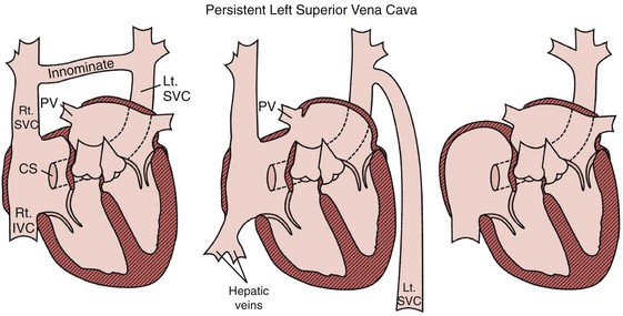
Figure 27-37 Persistent left superior vena cava (SVC).
(From Castle LW, Cook S: Pacemaker radiography. In Ellenbogen KA, Kay GN, Wilkoff BL, editors: Clinical cardiac pacing. Philadelphia, 1995, Saunders, p 588.)
Dextrocardia
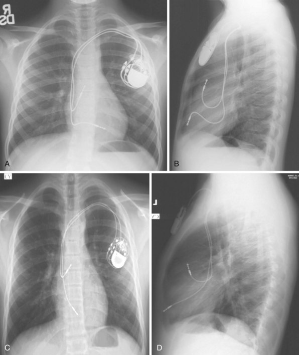
Dextrocardia should be recognized on the preprocedural chest radiograph (Fig. 27-39), particularly because its presence may affect on which side an ICD system may be placed. It is important to note the position of the stomach bubble on the chest radiograph in patients with dextrocardia. In those with situs inversus totalis, in whom the normal right-versus-left position of all organs is completely reversed, the stomach bubble is also right-sided (Fig. 27-39, D). In those with discordance of cardiac position and abdominal organ position (e.g., dextrocardia with a left-sided stomach bubble), situs inversus totalis is ruled out, and some form of heterotaxy syndrome is present. Patients with heterotaxy syndrome have a high incidence of abnormal systemic venous return and other cardiac anomalies (Fig. 27-40).
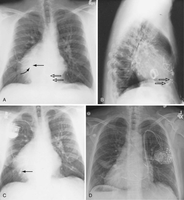
Figure 27-39 Dextrocardia.
(A to C from Castle LW, Cook S: Pacemaker radiography. In Ellenbogen KA, Kay GN, Wilkoff BL, editors: Clinical cardiac pacing. Philadelphia, 1995, Saunders, p 549.)
Senning and Mustard Procedures
Palliative surgery for some congenital heart disease includes creation of intra-atrial baffles that direct systemic venous blood return to the pulmonary ventricle and pulmonary venous return to the systemic ventricle, using either the Senning or Mustard procedure. A majority of patients undergoing palliation with a Senning or Mustard procedure have D- (“uncorrected”) or L- (“corrected”) transposition of the great arteries. In D-transposition of the great arteries, leads for permanent pacemakers or ICDs are typically placed via the SVC to the morphologic left atrium and left ventricle (Figs. 27-41 to 27-43). In L-transposition of the great arteries, after the “double-switch” procedure (Senning or Mustard and great arterial switch), the leads are placed via the SVC through the intra-atrial baffle to the left-sided atrium and left-sided morphologic right ventricle (Fig. 27-44).
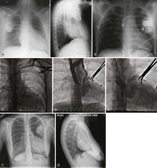
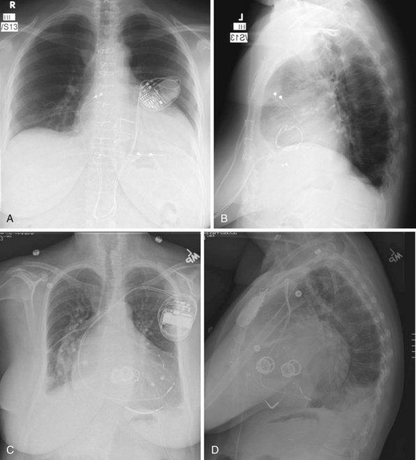
Figure 27-41 Device systems in D-transposition (uncorrected) of great arteries (DTGA) after Mustard procedure.
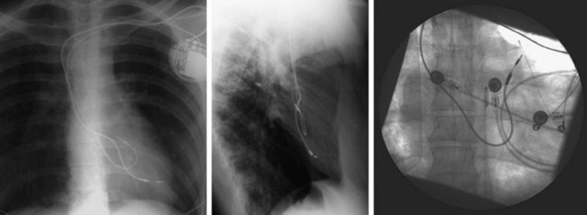
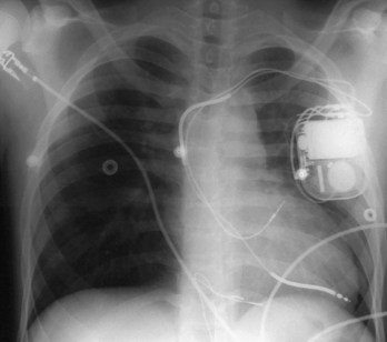
Figure 27-43 Transvenous ICD system implanted in pediatric patient after Senning procedure for D-transposition of great arteries.
Tetralogy of Fallot
Patients with tetralogy of Fallot have normal AV and ventriculoarterial (VA) connections, so the intravenous course of pacing and defibrillation leads is similar to that in patients with normal cardiac anatomy. Patients with this disorder have a higher incidence of persistent left-sided SVC than the general population (Fig. 27-45).
 Implantation Fluoroscopy and Venography
Transvenous Access Venography
The first and second ribs and clavicle serve as the standard landmarks in accessing the axillary/subclavian vein on either the left or the right side. The part of the vein inferolateral to the clavicle and at the lateral border of the first rib is typically considered the axillary vein, and the portion medial to this region, coursing under the clavicle, the subclavian vein (see Fig. 27-9). Cephalic vein access is usually achieved through venous cutdown under direct visualization, whereas axillary/subclavian access is through a percutaneous puncture using bony landmarks or fluoroscopy to help avoid pneumothorax.
In patients with morbid obesity, bony deformities, previous subclavian venous central line access, prior upper-extremity deep vein thrombosis, congenital heart disease, or preexisting leads, venous access can be difficult because of stenosis or altered relationships among the venous system, ribs, and clavicle. In these cases, ipsilateral upper-extremity venography can be very helpful in defining the course and patency of the axillary/subclavian system. Preoperative upper-extremity venograms to assess the patency in patients with previously implanted leads (see Fig. 27-9) are also often helpful, although intraoperative fluoroscopic or cineangiographic venography can be performed with simultaneous venous access.33 A left-sided SVC may also be confirmed with venography.
Traditional Pacing Sites
The right atrial lead follows the contour of the vascular system without excess redundancy, except in cases of venous tortuosity, but with a J-shaped lead, slack is generally left at the distal portion of the lead. Right ventricular leads are generally placed with enough lead slack to allow for lift and closure of the tricuspid valve. Lack of this lifting motion during fluoroscopy may signify a diseased tricuspid valve or tethering of the tricuspid leaflets or chordae by the pacing or ICD lead. In the latter case, repositioning of the lead requires withdrawal of the lead tip back to the right atrium and fresh entry to the right ventricle between leaflets. Radiographically, a lead positioned at the RVA displays the tip of the lead pointing slightly downward in the AP view and anteriorly on the lateral view; posterior angulation of the lead suggests positioning in the CS. A lead placed onto the RVOT or septum is located more cranially (see Fig. 27-31). An LAO or a left lateral view may help to determine septal rather than anterior wall location. Undue tension on leads may result in dislodgment or poor pacing thresholds (Fig. 27-46). In children, greater lead redundancy is desirable to allow for future growth, without causing excessive tension on the pacing or ICD lead.34
Alternative-Site Pacing
Pacing strategies to suppress atrial arrhythmias have involved selective alternate–atrial site or dual–atrial site pacing. Pacing the high septum of the right atrium, near Bachmann’s bundle or the CS os, may shorten intra-atrial conduction and minimize dispersion of refractoriness, perhaps improving atrial fibrillation.8,9 Fluoroscopically, the right atrial (RA) lead is directed in the LAO view toward the interatrial septum and then withdrawn until the tip begins to straighten, indicating proximity to the RA roof, where it is then fixed to the high septum. The position appears anteriorly directed on the RAO view.9 The LAO projection is helpful in guiding leads to the low RA septum. The target is the low septum just superior to the CS os and below the foramen ovale. Traditional RVA pacing may cause a dyssynchronous left ventricular electrical activation pattern, resulting in dyssynchronous contraction and relaxation that can contribute to heart failure and reduce long-term survival.35–37
Therefore, alternative–ventricular site pacing has become more conventional. The RVOT or septum has been targeted for right ventricular (RV) leads (see Figs. 27-16 and 27-31). These sites may also be used when pacing thresholds are high at the apex or if an ICD lead is present at the apex and separation is required to prevent device-device interactions (see Fig. 27-17).38 The lead may be placed with use of the AP or RAO view, with a gently curved stylet to help advance the lead through the tricuspid valve to the RVOT or pulmonary artery. The lead is then slowly withdrawn with counterclockwise torque to aim the tip toward the RVOT septum, where it can be actively fixed. The LAO view can be used to help determine whether the lead tip is septally or anteriorly directed. His bundle pacing has also been targeted on the RV septum with the goal of maintaining synchronous ventricular activation during ventricular pacing.
Leads and Complications
Coronary Sinus Venography and Lead Placement
Coronary sinus venography and lead placement are described previously in this chapter and in detail in Chapter 22.
Azygos Venography and Lead Placement
The azygos vein may be a target for ICD defibrillation leads in patients with high DFT (see Figs. 27-11 and 27-34). The azygos vein may be cannulated in the LAO projection and enters the SVC posteriorly just at or below its origin at the confluence of the right and left brachiocephalic veins. The vein often is acutely angled cranially and may require special guiding catheters (e.g., an internal mammary artery [IMA] catheter) to aid in introduction of a guidewire. Venography is often helpful in determining the ostium of the azygos vein and to define its course and branches.
Subcutaneous Patch, Coil, or Array
Defibrillation leads intended for subcutaneous implantation in patients with high DFT have been designed to contain a single coil, a multicoil array, or a patch electrode that can increase the surface area of the defibrillation vector (see Fig. 27-32). These subcutaneous electrodes may be placed across the posterolateral wall of the chest to provide a more posterior vector, or to the left pectoral region in the absence of a left pectoral active-can ICD. The lead system may be best visualized on the lateral chest radiograph or an RAO or LAO fluoroscopic view.28
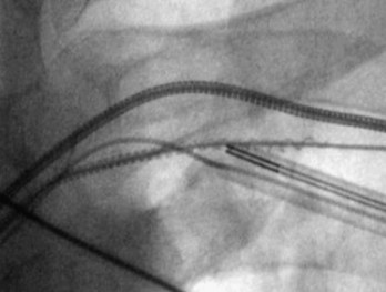
Lead Extraction
The tip of the telescoping sheath used for lead extraction is radiopaque and is continuously monitored by means of fluoroscopy while being advanced along the course of the lead (Fig. 27-47). Often, the leads are fibrosed and calcified and are clearly visible with fluoroscopy. Also, the dimensions and configuration of the cardiac silhouette and obliteration of the left hemidiaphragm should be followed closely to enable prompt recognition of cardiac tamponade. (See Chapter 26.)
 Postimplantation Radiography
A chest radiograph should be obtained after implantation of a pacemaker or ICD system. Postprocedural PA and lateral chest radiographs can confirm the correct and stable position of the generator and leads and assess for complications, such as ipsilateral or contralateral pneumothorax, pleural effusion or hemothorax, and even retained surgical sponges.39
Complications
Pneumothorax
Pneumothorax is best demonstrated on an upright PA view in full expiration. Pneumothorax is characterized by absence of lung markings over the lung fields (Fig. 27-48). The border of the lung apex, surrounded by clear air space inside the thoracic cavity, may be visualized. In rare cases the leads have punctured the SVC, causing a contralateral pneumothorax and usually associated with contralateral hemothorax.
Hemothorax
Hemothorax is an unusual complication during routine lead placement. Venous tears during lead extraction, however, can be associated with clinically significant hemothorax, which is usually evident during the procedure. Rarely, delayed ooze into the pleural space caused by subclavian vein or SVC laceration can result in significant pleural leak (Fig. 27-49). A hemothorax or pleural effusion is best recognized on upright PA or lateral chest radiograph.
Pericardial Effusion, Cardiac Perforation, and Cardiac Tamponade
Although the cardiac silhouette may be seen to enlarge on chest radiography, particularly compared with the preimplantation chest radiographs, one should not rely on the chest radiograph for a diagnosis of pericardial effusion. If there is clinical suspicion of a pericardial effusion, an echocardiogram should be obtained. Effacement of the left hemidiaphragm with enlarged cardiac silhouette compared with the preprocedural chest radiographs usually indicates pericardial effusion. An extracardiac location of the tip of the pacing lead suggests cardiac perforation with migration of the lead outside the heart (Fig. 27-50). Unless there is significant migration of the lead tip past the cardiac shadow, the chest radiograph may be insensitive to detection of cardiac perforation, and other imaging modalities, such as echocardiography and cardiac CT, may help determine whether a lead is indeed extracardiac in location.40
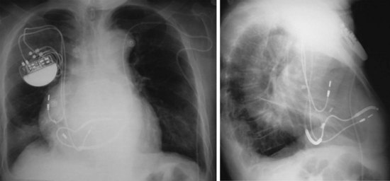
Lead Dislodgment
Postimplantation chest radiography helps confirm the position of the lead. Incomplete fixation of the lead screw and insufficient slack caused by inadvertent pulls on the lead during suturing of the sleeve can be causes of lead dislodgment. Atrial lead dislodgment may be suspected if the atrial lead hangs straight vertically, if a J shape was seen during implantation (see Fig. 27-50). Dislodgment of the atrial lead into the right ventricle may result in inappropriate ventricular pacing. Ventricular lead dislodgement may be recognized from proximal dislodgments of apically positioned leads or falling of the lead from a higher septal or RVOT location. Similarly, CS lead dislodgment can also be recognized on AP and lateral chest radiographs.
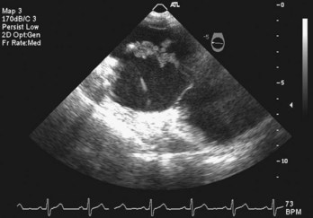
 Echocardiography
Complications
 Computed Tomography
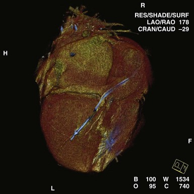
In certain patients before and after implantation, CT may clarify the anatomy of congenital or repaired anomalies, greatly aiding in the planning of appropriate approaches to lead implantation. Cardiac CT has also been used in the diagnosis of arrhythmogenic right ventricular dysplasia (ARVD).41 Postprocedural applications include the assessment of lead tip migration, cardiac perforation, and pericardial effusion. Cardiac CT has been used in the past to assess epicardial ICD patch location and the extent of myocardial coverage, as well as relationships to the underlying myocardium. Most often, CT may be used as a substitute for MRI in patients with pacemakers and ICDs. Multislice CT is being investigated for assessment of CS anatomy, which may help determine candidacy for transvenous versus epicardial approaches to CRT42 (Figs. 27-52 and 27-53). Integration of CT with real-time lead positioning is also being explored.
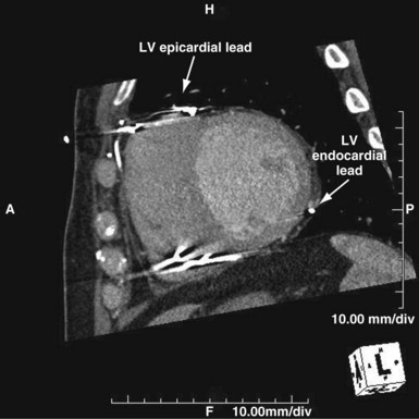
Figure 27-52 Computed tomography scan in patient presenting as “nonresponder” to biventricular pacing.
 Magnetic Resonance Imaging
Cardiac MRI has generally been contraindicated in patients with implanted pacemakers or ICDs. However, several investigators have studied the safety of noncardiac MRI in patients with implanted pacemakers. Potential risks include heating of leads, rapid or asynchronous pacing, reed switch inhibition, and induction of ventricular fibrillation.43 Use of noncardiac MRI of varying static magnetic field strengths has been reported in more than 300 patients with implanted pacemakers.44 Pacing threshold changes have been reported, but no adverse patient events. Studies have generally avoided pacemaker-dependent subjects. Thus, data so far suggest that patients who are not pacemaker dependent may safely undergo noncardiac MRI at specific absorption rates (SARs) of less than 2 W/kg.44–46 The pacemaker should be interrogated before the procedure to assess pacemaker dependence and inactivate minute ventilation or other rate-response features. Outputs may be programmed to subthreshold levels, but this step may not be necessary. The patient should be continuously monitored and personnel familiar with pacemakers present in case emergency programming is required. After the procedure, the pacemaker should again be interrogated and a full check performed, including threshold testing.
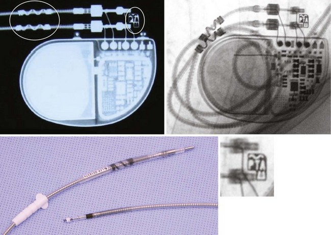
Currently, MRI is contraindicated in patients with ICDs. Although future generations of ICDs may become MRI safe, there may be a higher risk of current induction through the defibrillation coils, and MRI in patients with these devices has not been well studied. Nevertheless, cardiac implantable electronic devices (CIEDs), including leads and pacemakers, which are MRI compatible have been under development. These devices may be identified by proprietary markings (Fig. 27-54).
 Conclusion
1 Hill P. Complications of permanent transvenous cardiac pacing: a 14-year review of all transvenous pacemakers inserted at one community hospital. Pacing Clin Electrophysiol. 1987;10:564.
2 Filice R. Cardiac pacemaker leads: a radiographic perspective. Can Assoc Radiol J. 1984;35:20.
3 Lappegard K. Pacemaker implantation in patients with persistent left superior vena cava. Heart Vessels. 2004;19:153.
4 Cesario D, Bhargava M, Valderrabano M, et al. Azygos vein lead implantation: a novel adjunctive technique for implantable cardioverter defibrillator placement. J Cardiovasc Electrophysiol. 2004;15:780.
5 Bongiorni MG, Moracchini PV, Nava A, et al. Radiographic assessment of atrial dipole position in single pass lead VDD and DDD pacing. The Multicenter Study Group. Pacing Clin Electrophysiol. 1998;21:2240.
6 Hertzberg BS, Chiles C, Ravin CE. Right atrial appendage pacing: radiographic considerations. AJR Am J Roentgenol. 1985;145:31.
7 Daubert C, Gras D, Berder V, et al. [Permanent atrial resynchronization by synchronous biatrial pacing in the preventive treatment of atrial flutter associated with high-degree interatrial block]. Arch Mal Coeur Vaiss. 1994;87(suppl):1535.
8 Padeletti L, Michelucci A, Pieragnoli P, et al. Atrial septal pacing: a new approach to prevent atrial fibrillation. Pacing Clin Electrophysiol. 2004;27:850.
9 Bailin SJ, Adler S, Giudici M. Prevention of chronic atrial fibrillation by pacing in the region of Bachmann’s bundle: results of a multicenter randomized trial. J Cardiovasc Electrophysiol. 2001;12:912.
10 Van Gelder BM, Bracke FA, Oto A, et al. Diagnosis and management of inadvertently placed pacing and ICD leads in the left ventricle: a multicenter experience and review of the literature. Pacing Clin Electrophysiol. 2000;23:877.
11 Lieberman R, Grenz D, Mond HG, Gammage MD. Selective site pacing: defining and reaching the selected site. Pacing Clin Electrophysiol. 2004;27:883.
12 Deshmukh PM, Romanyshyn M. Direct His-bundle pacing: present and future. Pacing Clin Electrophysiol. 2004;27:862.
13 Kautzner J, Riedlbauchova L, Cihak R, et al. Technical aspects of implantation of LV lead for cardiac resynchronization therapy in chronic heart failure. Pacing Clin Electrophysiol. 2004;27:783.
14 Von Ludinghausen M. The venous drainage of the human myocardium. Adv Anat Embryol Cell Biol. 2003;168:I.
15 Fernandez AL, Garcia-Bengochea JR, Ledo R, et al. Minimally invasive surgical implantation of left ventricular epicardial leads for ventricular resynchronization using video-assisted thoracoscopy. Rev Esp Cardiol. 2004;57:313.
16 Zenati MA, Bonanomi G, Chin AK, Schwartzman D. Left heart pacing lead implantation using subxiphoid videopericardioscopy. J Cardiovasc Electrophysiol. 2003;14:949.
17 Derose JJJr, Belsley S, Swistel DG, et al. Robotically assisted left ventricular epicardial lead implantation for biventricular pacing: the posterior approach. Ann Thorac Surg. 2004;77:1472.
18 Roelke M, O’Nunain SS, Osswald S, et al. Subclavian crush syndrome complicating transvenous cardioverter defibrillator systems. Pacing Clin Electrophysiol. 1995;18:973.
19 Weiner S, Patel J, Jadonath RL. Lead failure due to the subclavian crush syndrome in a patient implanted with both standard and thin bipolar spiral wound leads. Pacing Clin Electrophysiol. 1999;22:975.
20 Hecht S, Berdoff R, Van Tosh A, Goldberg E. Radiographic pseudofracture of bipolar pacemaker wire. Chest. 1985;88:302.
21 Weissman JL, Kanel KT. Ligature causing pseudofracture of a cardiac pacemaker lead. AJR Am J Roentgenol. 1996;166:464.
22 Fahraeus T, Hoijer CJ. Early pacemaker twiddler syndrome. Europace. 2003;5:279.
23 Carnero-Varo A, Perez-Paredes M, Ruiz-Ros JA, et al. “Reel syndrome”: a new form of twiddler’s syndrome? Circulation. 1999;100:e45.
24 Lloyd MA, Hayes DL, Holmes DRJr. Atrial “J” pacing lead retention wire fracture: radiographic assessment, incidence of fracture, and clinical management. Pacing Clin Electrophysiol. 1995;18:958.
25 Daoud EG, Kou W, Davidson T, et al. Evaluation and extraction of the Accufix atrial J lead. Am Heart J. 1996;131:266.
26 Byrd CL, Wilkoff BL, Love CJ, et al. Intravascular extraction of problematic or infected permanent pacemaker leads: 1994-1996. U.S. Extraction Database, MED Institute. Pacing Clin Electrophysiol. 1999;22:1348.
27 Stanton MS, Hayes DL, Munger TM, et al. Consistent subcutaneous prepectoral implantation of a new implantable cardioverter defibrillator. Mayo Clin Proc. 1994;69:309.
28 Avitall B, Oza SR, Gonzalez R, Avery R. Subcutaneous array to transvenous proximal coil defibrillation as a solution to high defibrillation thresholds with implantable cardioverter defibrillator distal coil failure. J Cardiovasc Electrophysiol. 2003;14:314.
29 Kratz JM, Schabel S, Leman RM. Pseudofracture of a defibrillating lead. Pacing Clin Electrophysiol. 1995;18:2225.
30 Taliercio CP, Vliestra RE, McGon MD, et al. Permanent cardiac pacing after the Fontan procedure. J Thorac Cardiovasc Surg. 1985;90:414.
31 Alexander ME, Cecchin F, Walsh EP, et al. Implications of implantable cardioverter defibrillator therapy in congenital heart disease and pediatrics. J Cardiovasc Electrophysiol. 2004;15:72.
32 Biffi M, Boriani G, Frabetti L, et al. Left superior vena cava persistence in patients undergoing pacemaker or cardioverter-defibrillator implantation: a 10-year experience. Chest. 2001;120:139.
33 Higano ST, Hayes DL, Spittell PC. Facilitation of the subclavian-introducer technique with contrast venography. Pacing Clin Electrophysiol. 1990;13:681.
34 Gheissari A, Hordof AJ, Spotnitz HM. Transvenous pacemakers in children: relation of lead length to anticipated growth. Ann Thorac Surg. 1991;52:118.
35 Bedotto JB, Grayburn PA, Black WH, et al. Alterations in left ventricular relaxation during atrioventricular pacing in humans. J Am Coll Cardiol. 1990;15:658.
36 Stojnic BB, Stojanov PL, Angelkov L, et al. Evaluation of asynchronous left ventricular relaxation by Doppler echocardiography during ventricular pacing with AV synchrony (VDD): comparison with atrial pacing (AAI). Pacing Clin Electrophysiol. 1996;19:940.
37 Tse HF, Lau CP. Long-term effect of right ventricular pacing on myocardial perfusion and function. J Am Coll Cardiol. 1997;29:744.
38 Epstein AE, Kay GN, Plumb VJ, et al. Combined automatic implantable cardioverter-defibrillator and pacemaker systems: implantation techniques and follow-up. J Am Coll Cardiol. 1989;13:121.
39 Grier D, Cook PG, Hartnell GG. Chest radiographs after permanent pacing: are they really necessary? Clin Radiol. 1990;42:244.
40 Sussman SK, Chiles C, Cooper C, Lowe JE. CT demonstration of myocardial perforation by a pacemaker lead. J Comput Assist Tomogr. 1986;10:670.
41 Tandri H, Bomma C, Calkins H, Bluemke DA. Magnetic resonance and computed tomography imaging of arrhythmogenic right ventricular dysplasia. J Magn Reson Imaging. 2004;19:848.
42 Jongbloed MR, Lamb HJ, Box JJ, et al. Noninvasive visualization of the cardiac venous system using multislice computed tomography. J Am Coll Cardiol. 2005;45:749.
43 Sakakibara Y, Mitsui T. Concerns about sources of electromagnetic interference in patients with pacemakers. Jpn Heart J. 1999;40:737.
44 Martin ET. Can cardiac pacemakers and magnetic resonance imaging systems co-exist? Eur Heart J. 2005;26:325.
45 Martin ET, Coman JA, Shelloch FG, et al. Magnetic resonance imaging and cardiac pacemaker safety at 1.5-Tesla. J Am Coll Cardiol. 2004;43:1315.
46 Roguin A, Zviman MM, Meininger GR, et al. Modern pacemaker and implantable cardioverter/defibrillator systems can be magnetic resonance imaging safe: In vitro and in vivo assessment of safety and function at 1.5 T. Circulation. 2004;110:475.