Image receptors
Radiographic film
• Direct-action or non-screen film (sometimes referred to as wrapped or packet film). This type of film is sensitive primarily to X-ray photons.
• Indirect-action or screen film, so-called because it is used in combination with intensifying screens in a cassette. This type of film is sensitive primarily to light photons, which are emitted by the adjacent intensifying screens. They respond to shorter exposure of X-rays, enabling a lower dose of radiation to be given to the patient.
Direct-action (non-screen) film
Uses
The film packet contents
The contents of a film packet are shown in Fig. 4.2. It is worth noting that:
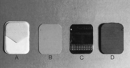
• The outer packet or wrapper is made of non-absorbent paper or plastic and is sealed to prevent the ingress of saliva.
• The side of the packet that faces towards the X-ray beam has either a pebbled or a smooth surface and is usually white.
• The reverse side is usually of two colours so there is little chance of the film being placed the wrong way round in the patient’s mouth and different colours represent different film speeds.
• The black paper on either side of the film is there to protect the film from:
• A thin sheet of lead foil is placed behind the film to prevent:
– Some of the residual radiation that has passed through the film from continuing on into the patient’s tissues
– Scattered secondary radiation, from X-ray photon interactions within the tissues beyond the film, scattering back on to the film and degrading the image.
• The sheet of lead foil contains an embossed pattern so that should the film packet be placed the wrong way round, the pattern will appear on the resultant radiograph. This enables the cause of the resultant pale film to be easily identified (see Ch. 17).
The radiographic film
The cross-sectional structure and components of the radiographic film are shown in Fig. 4.3. It comprises four basic components:
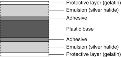
• A plastic base, made of clear, transparent cellulose acetate – acts as a support for the emulsion but does not contribute to the final image
• A thin layer of adhesive – fixes the emulsion to the base
• The emulsion on both sides of the base – this consists of silver halide (usually bromide) crystals embedded in a gelatin matrix. The X-ray photons sensitize the silver halide crystals that they strike and these sensitized silver halide crystals are later reduced to visible black metallic silver in the developer (see Ch. 5)
• A protective layer of clear gelatin to shield the emulsion from mechanical damage.
Indirect-action film
Uses
Indirect-action film construction
• The silver halide emulsion is designed to be sensitive primarily to light rather than X-rays.
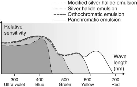
• Different emulsions are manufactured which are sensitive to the different colours of light emitted by different types of intensifying screens (see later). These include:
The relative spectral sensitivity of these four different film emulsions is shown in Fig. 4.4.
Characteristics of radiographic film

Characteristic curve
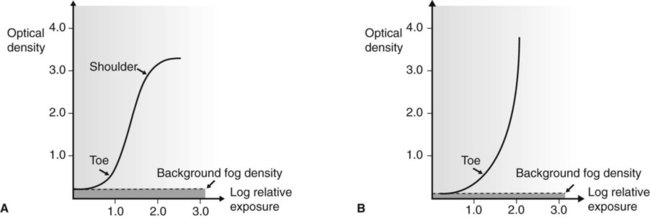
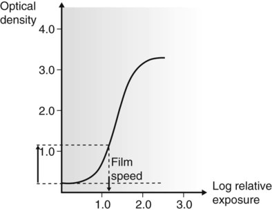
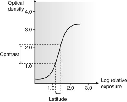
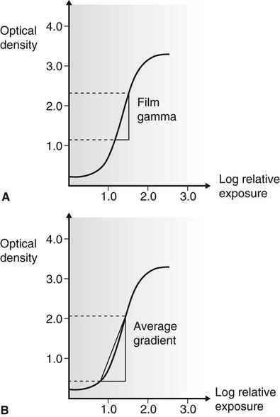
The characteristic curve is a graph showing the variation in optical density (degree of blackening) with different exposures. Typical characteristic curves for direct-action (non-screen) and indirect-action (screen) film are shown in Fig. 4.5. This curve describes several of the film’s properties.
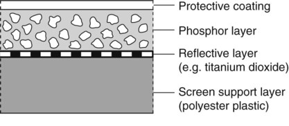
Intensifying screens
Intensifying screens consist of fluorescent phosphors, which emit light when excited by X-rays, embedded in a plastic matrix. The basic construction and components of an intensifying screen are shown in Fig. 4.9.
Action
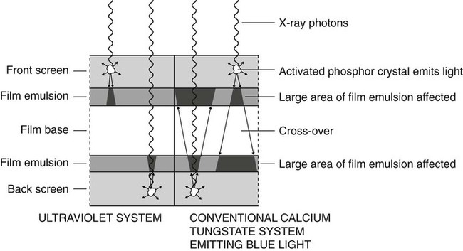
Two intensifying screens are used – one in front of the film and the other at the back. The front screen absorbs the low-energy X-ray photons and the back screen absorbs the high-energy photons. The two screens are therefore efficient at stopping the transmitted X-ray beam, which they convert into visible light by the photoelectric effect (described in Ch. 2). One X-ray photon will produce many light photons which will affect a relatively large area of film emulsion. Thus, the amount of radiation needed to expose the film is reduced but at the cost of fine detail; resolution is decreased. The ultraviolet system was developed to improve resolution by reducing light diffusion and having virtually no light crossover through the plastic film base (see Fig. 4.10).
Useful definitions
The following terms are used to describe intensifying screens:
• Conversion efficiency – the efficiency with which the phosphor converts X-rays into light
• Absorption efficiency – the ability of the phosphor material to absorb X-rays
• Screen efficiency – the ability of the light emitted by the phosphor to escape from the screen and expose the film
• Screen speed – the time taken for the screen to emit light following exposure to X-rays. The faster the screen, the lower the radiation dose to the patient
• Packing density – the ability of the phosphor to pack closely together resulting in thin screens and less light divergence.
Fluorescent materials
Three main phosphor materials are, or have been, used in intensifying screens:
• Rare earth phosphors including gadolinium and lanthanum
• Yttrium (a non-rare earth phosphor but having similar properties)
Rare earth and related screens
• The rare earth group of elements includes:
• The term rare earth is used because it is difficult and expensive to separate these elements from earth and from each other, not because the elements are scarce.
• These phosphors only fluoresce properly when they contain impurities of other phosphors, e.g. gadolinium plus 0.3% terbium. Typical screens include:
• Terbium-activated screens emit GREEN light, while thulium-activated screens emit BLUE light (see Fig. 4.11).
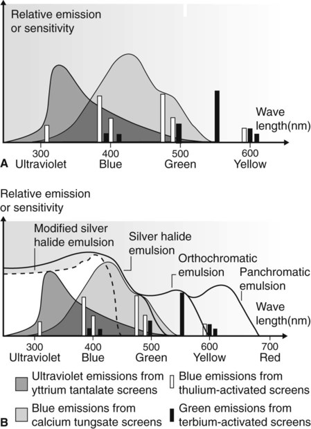
• Yttrium (Z = 39), the rare earth related phosphor, in the form of pure yttrium tantalate (YtaO4) emits ULTRAVIOLET light (see Fig. 4.11).
• Rare earth and related screens are approximately five times faster than calcium tungstate screens. The amount of radiation required to produce an image is therefore considerably reduced, but they are relatively expensive.
• Several different screens of each phosphor, each producing a different image system speed, are available:
| Screen type | Image system speed |
| Detail or Fine | 100 |
| Fast detail or Medium | 200 |
| Rapid or Fast | 400 |
| Super rapid | 800 |
• It is important to use the appropriate films with their correctly matched screens.
Calcium tungstate screens
• The speed of these screens depends upon:
– The thickness of the phosphor layer
– The size of the phosphor crystals
– The presence or absence of light-absorbing dyes within the screen
• The faster the screen, the lower the radiation dose to the patient but the less the detail of the final image
• All calcium tungstate screens emit BLUE light and must be used with blue-light-sensitive monochromatic radiographic film (see Fig. 4.11).
Cassettes
Types
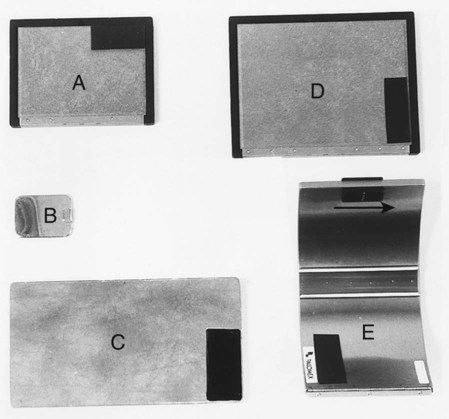
Cassettes are made in a variety of shapes and sizes for different projections. A selection is shown in Fig. 4.12.
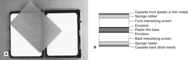
Construction
Despite their different shapes, the construction of the cassettes is very similar. They usually consist of a light-tight aluminium or carbon fibre container with the radiographic film sandwiched tightly between two intensifying screens (see Fig. 4.13). Any loss in film/screen contact will result in degradation of the final image.
Important practical points to note
Film storage
• In a refrigerator in cool, dry conditions
• Away from all sources of ionizing radiation
• Away from chemical fumes including mercury and mercury-containing compounds
• With boxes placed on their edges, to prevent pressure artefacts.
Digital receptors
There are two types of direct digital image receptors available, namely:
Solid-state sensors
Intraoral sensors
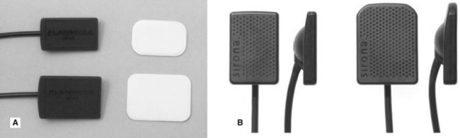
The intraoral sensors are small, thin, flat, rigid rectangular boxes, usually black in colour and similar in size to intraoral film packets. They vary in thickness from about 5 to 7 mm as shown in Fig. 4.14. Most sensors are cabled to allow data to be transferred directly from the mouth to the computer. Several systems are now available.
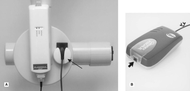
For ease of clinical use the sensor cables are usually 1–2 m long and plug into a remote docking station which can be conveniently attached to the tubehead supporting arm (see Fig. 4.15). A separate cable then connects the docking station to the computer.
The solid-state sensors are NOT autoclavable. When used clinically they all need to be covered with a protective plastic barrier envelope for infection control purposes (see Ch. 8).
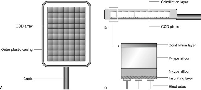
CCD (charge-coupled device)
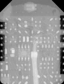
Individual pixels, consisting of a sandwich of P- and N-type silicon, are arranged in rows and columns called an array or matrix, above which is a scintillation layer made of similar materials to the rare-earth intensifying screens. The basic design is shown in Fig. 4.16 and the complex electronic circuitry required is shown in Fig. 4.17. The X-ray photons that hit the scintillation layer are converted to light. The light interacts via the photoelectric effect with the silicon to create a charge packet for each individual pixel, which is concentrated by the electrodes.
Extraoral sensors
• Flat cassette-sized sensors designed to be retro-fitted into existing film-based panoramic equipment to replace conventional cassettes.
• Individually designed sensors as part of completely new solely digital panoramic or skull equipment such as the Planmeca dimax3® (see Fig. 4.18).
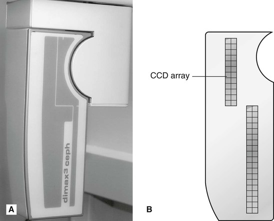
Although the outward appearances of these sensors is very different, both designs work in a similar fashion. A long narrow pixel array is aligned with a narrow slit-shaped X-ray beam and the equipment scans across the patient. This scanning motion takes several seconds to scan the skull and is discussed in more detail in Chapters 14 and 15.
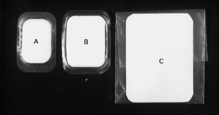
Photostimulable phosphor storage plates
A range of intraoral and extraoral plate sizes are available with these systems, identical in size to conventional periapical, occlusal, oblique lateral, panoramic and skull films (see Fig. 4.19). Once cleared (erased), the plates are reusable. Intraoral plates need to be inserted into protective barrier envelopes for control of infection purposes (see Fig. 4.20A).
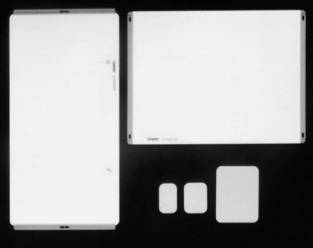
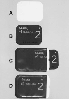
Plate construction and design
The plates typically consist of a layer of barium fluorohalide phosphor on a flexible plastic backing support, as shown in Fig. 4.21.
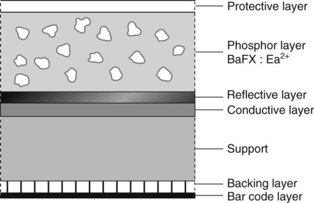
• The phosphor layer absorbs and stores the X-ray energy that has not been attenuated by the patient.
• The image plate is then placed in a reader where it is scanned by a laser beam. The stored X-ray energy in the phosphor layer is released as light which is detected by a photo-multiplier tube and converted into a voltage which is relayed to the computer and displayed as a digital image. This is described in more detail in Chapter 6.
To access the self assessment questions for this chapter please go to www.whaitesessentialsdentalradiography.com