Hysteroscopic Instrumentation
To perform operative hysteroscopy as well as panoramic diagnostic hysteroscopy, the potential uterine cavity must be distended to allow the operator to see. Although a large number and variety of instruments are available, the critical implements required to perform manipulative hysteroscopic examinations and procedures are few.
The first and most important device is the telescope, which permits vision within the uterine space. Typically, rigid telescopes measure 4 mm in outer diameter (O.D.) and contain optical rod lenses as well as fiberoptic light–transmitting elements (Fig. 106–1A through C).
The second element is the hysteroscopic sheath, which transmits the distention medium into the uterine cavity. For simple viewing, the sheath measures 5 mm O.D.; however, larger sheaths ranging in size from 7.5 to 9.0 mm O.D. are required for operative hysteroscopy (Fig. 106–2A, B). Contemporary sheaths should have isolated inflow and outflow channels to properly and continuously flush the uterine cavity (Fig. 106–3A through D). Some sheaths are specialized, for example, the resectoscopic sheath is specifically designed for electrosurgery (Fig. 106–4A through C).
Third, a high-powered (and preferably xenon) light generator is required to provide high-intensity light (Fig. 106–5). Coupled with the light generator is a video camera and monitor, because most if not all modern hysteroscopy is performed with the surgeon and assistants viewing the operative field via a video monitor (Fig. 106–6A, B). Recording equipment for still, video, or digital photography should be available to memorialize findings and to supplement the dictated operative report (Fig. 106–7).
Accessory instruments may be divided into conventional devices and energy-delivered implements. Among the conventional tools are scissors, grasping forceps, biopsy forceps, and suction cannulas (Fig. 106–8A, B). The energy devices include bipolar and unipolar needles, coagulating ball electrodes, and laser fibers (Fig. 106–9A, B). A specialized sheath commonly utilized for hysteroscopic surgery is the resectoscope. This consists of a flushing sheath, a number of double-armed monopolar electrodes, and a spring-loaded trigger mechanism to move the electrode out of the sheath and then return it back to the sheath (Fig. 106–10). The most convenient consolidation of the myriad pieces of equipment is the mobile, multilevel, storage cart (see Fig. 106–5).
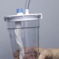
Finally, hysteroscopic infusion media (e.g., 32% dextran-70 [Hyskon], glycine, mannitol, saline) are vasoactive substances, which, because of pressure differentials, gain entry into the patient’s vascular space (Figs. 106–11 and 106–12). Therefore, every operative hysteroscopy performed must be accompanied by an accurate accounting of fluids in versus fluids out. The most accurate method of quantifying fluid outflow is to employ a drape fitted with a waterproof pouch in which to collect the exiting medium (Fig. 106–13).
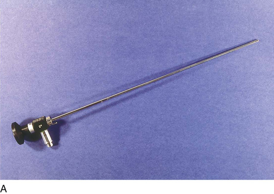


FIGURE 106–1 A. The telescope measures 4 mm O.D. and consists of an optic (viewing) and glass fibers that transmit light. B. Magnified view shows the magnifying eyepiece of the telescope and the connection for the fiberoptic cable that carries light from a remote generator to the telescope. C. This schematic drawing illustrates the components of the telescope. The objective lens is 0°, which produces a straight-on view, and the 30° scope gives an offset or angulated view of the object. From the objective, the image is transmitted by a series of rod lenses to the eyepiece.
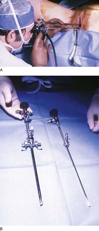
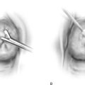
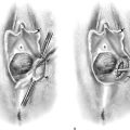
FIGURE 106–2 A. The telescope is fitted to a 5-mm diagnostic sheath, and the chosen medium is injected via the sheath to distend the cervix and corpus. The operator engages the scope at the external os and enters the cavity via direct vision. B. Operative (left) and diagnostic (right) sheaths are displayed side by side. The telescopes fitted to the sheaths are identical (4 mm O.D.).
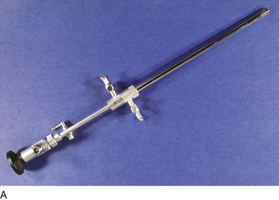
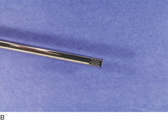
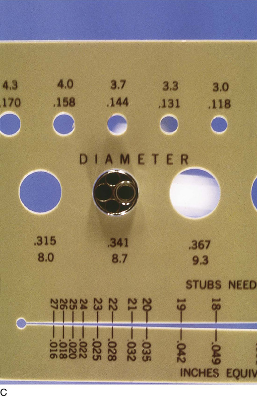
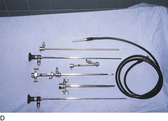
FIGURE 106–3 A. An isolated channel hysteroscope with a double sheath to allow return flow of the medium. The forward stopcock is for inflow; the aft stopcock is the outflow channel. B. The distal aspect of the sheath illustrated in Figure 106–3A. Perforations are present in the outer sheath and are the portal through which returning fluid enters the exterior sheath. C. The operative sheath is illustrated protruding through a measuring device. Note that the diameter of the hole is 8.7 mm. D. A complete instrument set includes diagnostic and operative sheaths, telescope, and fiberoptic light cable.
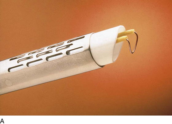
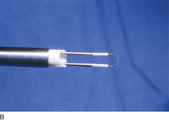
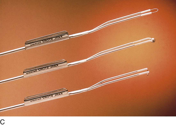
FIGURE 106–4 A. The resectoscope is a specially modified operative sheath that is suitable for monopolar electrosurgery. The sheath is a flushing type (double sheath). The electrode is an angulated loop supported by a double arm. B. The straight resectoscopic loop electrode is ideal for shaving or cutting lesions located at the fundus. C. A variety of electrodes are available for cutting, ablation, or coagulation.
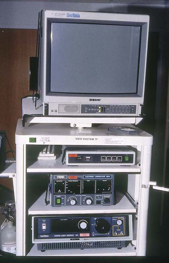
FIGURE 106–5 The large mobile instrument accessory cabinet contains a video monitor, a video control device, a fiberoptic light source, and a video recorder.

FIGURE 106–6 A. All contemporary hysteroscopic surgery is performed by viewing the field indirectly via the video screen. A small endoscopic TV camera attaches to the eyepiece of the telescope. B. The surgeon can sit up straight during hysteroscopic surgery because the operative field can be viewed via a TV monitor. The assistants have, of course, the same view as the surgeon.

FIGURE 106–7 The digital printer permits permanent still picture records and slides to be produced from the operation.
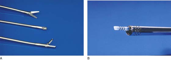
FIGURE 106–8 A. These conventional tools are inserted via the operative channel of the hysteroscopic sheath into the uterine cavity. At the top are scissors, in the middle is a direct-sampling curette, and at the bottom are alligator grasping forceps. B. A 3-mm aspirating cannula is useful for evacuating blood and debris from the uterine cavity.

FIGURE 106–9 A. A 1000-µm laser fiber is a useful tool for cutting, ablating, and coagulating. B. These three electrosurgical devices can be inserted through the operating channel. They are (from top to bottom) a 3-mm monopolar ball electrode, a bipolar two-prong needle electrode, and a 3-mm monopolar button electrode.

FIGURE 106–10 The trigger mechanism for advancing and retracting the resectoscopic electrode is shown here.
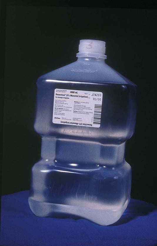
FIGURE 106–11 A variety of hysteroscopic media are available to distend the uterus. When monopolar devices are to be used, the safest medium to employ is 5% mannitol because it is iso-osmolar.

FIGURE 106–12 A uterine pump may be utilized to infuse fluid. The newer pumps will record pressure, fluid infused (mL), and fluids remaining in the reservoir.
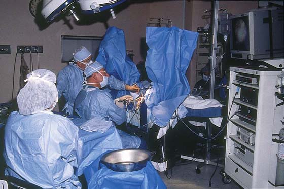
FIGURE 106–13 The pouch drape shown here collects fluid returning via the outflow valve of the hysteroscope. It likewise collects fluid flowing retrograde via the cervix.