[level-membership-for-orthopaedics-category]
CHAPTER 33 Humeral Surface Replacement
The advantage of complete surface replacement of the humeral head lies mainly in preservation of subchondral bone.1 In our practice, few situations exist in which complete surface replacement of the humeral head is more advantageous than conventional humeral head replacement with a stemmed implant. Additionally, use of these surface replacement implants hinders glenoid exposure and thus prevents implantation of a prosthetic glenoid implant in many cases.
INDICATIONS AND CONTRAINDICATIONS
Complete Surface Replacement
We rarely perform complete surface replacement of the humeral head in our practice. As detailed in Chapter 6, we perform glenoid resurfacing in most shoulder arthroplasty candidates with an indication other than acute fracture. The most common indication for which we will use a complete humeral surface replacement is early-stage humeral head osteonecrosis in an active patient younger than 50 years in whom the segment of necrotic bone is sufficiently small that it will not jeopardize implant fixation, typically less than 25% of the humeral head. An additional indication is an exceptionally young, otherwise healthy patient who is a candidate for shoulder arthroplasty. Most of our patients falling into this category have chondrolysis of the glenohumeral joint after an arthroscopic instability procedure. In these cases we will consider use of a complete humeral head surface replacement combined with biologic resurfacing of the glenoid (see Chapter 34).
In addition to the standard contraindications to unconstrained shoulder arthroplasty (see Chapter 6), any condition jeopardizing implant fixation is a contraindication to humeral head surface replacement (i.e., proximal humeral fracture, extensive proximal humeral osteonecrosis). Moreover, insertion of a standard polyethylene glenoid component is a relative contraindication to use of a humeral head surface replacement, and in the vast majority of cases a conventional stemmed humeral implant should be used instead. As detailed in Chapter 10, glenoid exposure is the most important portion of prosthetic glenoid resurfacing, and preservation of a portion of the humeral head should never be favored over optimal glenoid exposure. Conversely, biologic resurfacing typically does not involve correction of glenoid deformity and does not entail the use of a pegged or keeled glenoid component. These concessions usually make biologic glenoid resurfacing possible with the more limited glenoid exposure available during humeral head resurfacing.
Partial Surface Replacement
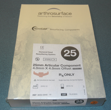
Partial surface replacement is indicated in patients with localized full-thickness defects of the articular cartilage of the humeral head who have failed other treatments. When patients with full-thickness articular cartilage lesions of the humeral head are seen in our practice, we initially treat them nonoperatively with nonsteroidal anti-inflammatory medications, selective rest, and activity modification for a period of 6 to 12 weeks. If such treatment proves unsuccessful, we offer arthroscopic treatment of the lesion with débridement and drilling of subchondral bone to stimulate the formation of fibrocartilage. If patients remain symptomatic 6 months after arthroscopic treatment, we will offer them partial surface replacement. In patients older than 30 years, we opt for prosthetic replacement with a metallic device (Hemicap, Arthrosurface, Inc., Franklin, MA). In younger patients, we opt for matched osteochondral allograft replacement. In our experience, it is rare for a patient to fail arthroscopic treatment of these localized articular cartilage lesions, thus minimizing the indications for partial surface replacement.
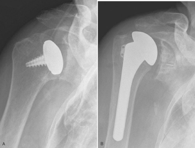
Contraindications specific to partial surface replacement include cartilaginous lesions larger than 35 mm in diameter (the diameter of the largest implant available), the presence of nonlocalized disease (Fig. 33-1), and the absence of sufficient bone quality to support the implant.
TECHNIQUE FOR PROSTHETIC RESURFACING
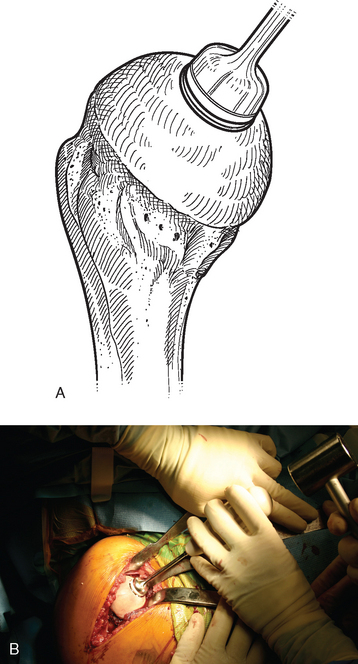
The operating room setup, anesthesia, patient positioning, skin preparation, surgical draping, and surgical approach are identical to that for humeral surface replacement and other shoulder arthroplasties (see Chapters 3, 4, and 8). The first difference in the technique involves handling of the anterior humeral circumflex vessels and subscapularis. When performing humeral surface replacement, we prefer to leave the anterior humeral circumflex vessels intact to maintain optimal blood flow to the humeral head. Consequently, after placing stay sutures in the subscapularis tendon as for unconstrained shoulder arthroplasty, we end our subscapularis tenotomy just superior to the anterior humeral circumflex vessels (Fig. 33-2). Subscapularis and capsular release is rarely necessary in patients undergoing humeral surface replacement. Next, the humeral head is dislocated by externally rotating and extending the arm. Hohmann retractors are placed circumferentially around the humeral head to complete the proximal humeral exposure (Fig. 33-3).
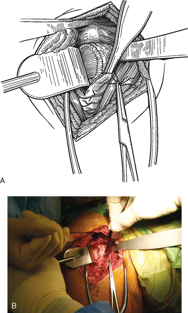
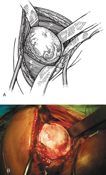
Figure 33-3 A and B, Completed proximal humeral exposure for surface replacement of the humeral head.
Complete Surface Replacement
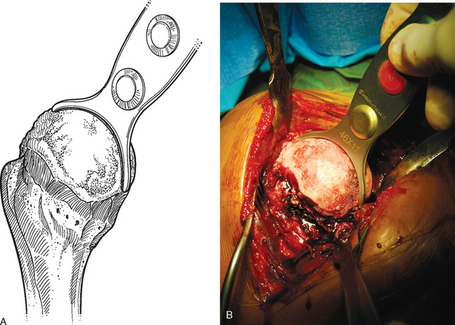
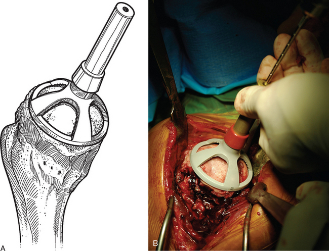
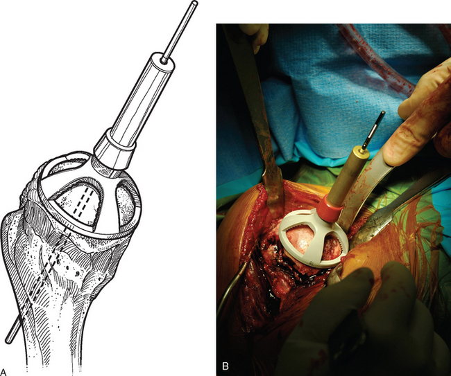
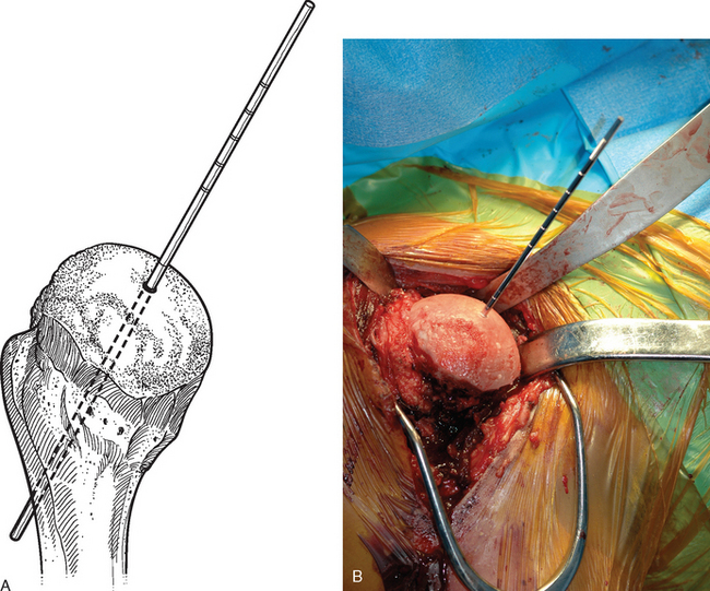
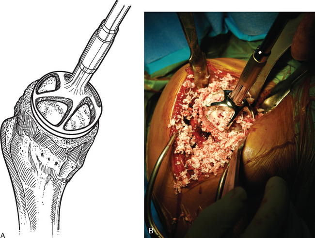
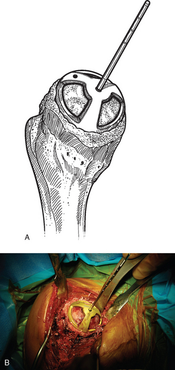
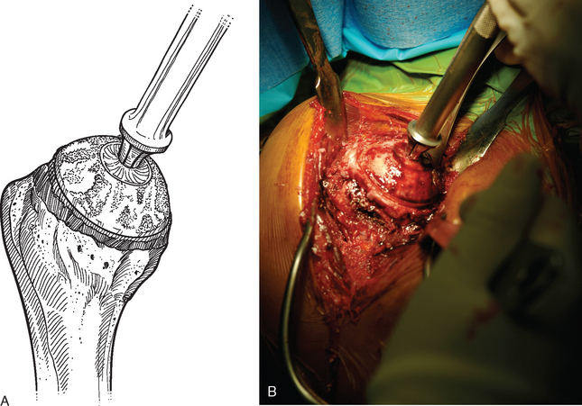
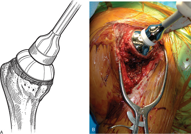
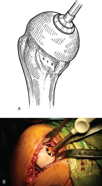
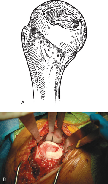
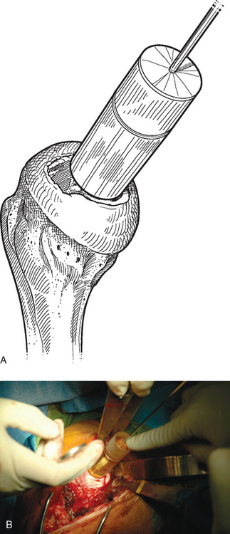
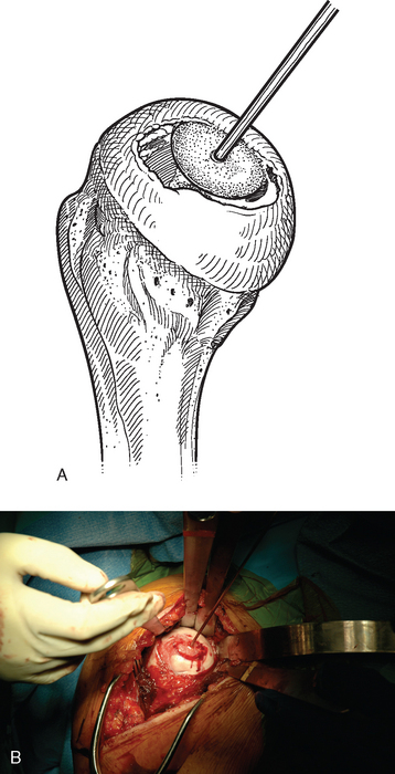
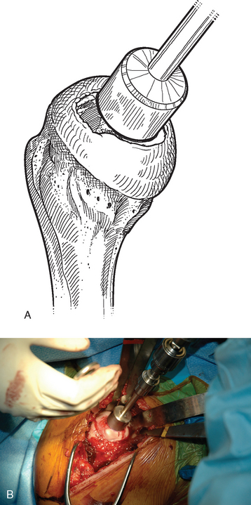
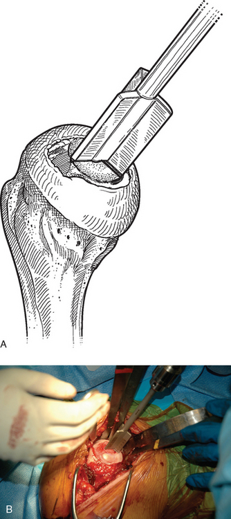
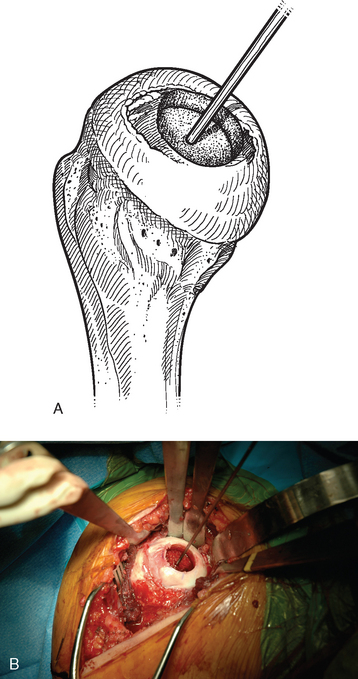
For complete surface replacement, we use a system (Tornier, Inc., Stafford, TX) that allows the same 12 different humeral head sizes available for stemmed unconstrained arthroplasty. We believe that selection of the appropriate humeral head size is no less important in humeral surface replacement than in stemmed humeral arthroplasty. After exposure of the humeral head is complete and peripheral humeral osteophytes are removed, the size of the humeral head is determined with the sizing guides (Fig. 33-4). If the native humeral head is between two sizes, the smaller size is selected. The pin guide corresponding to the selected humeral head size is centered over the humeral articular surface (Fig. 33-5). The guide pin is drilled into the proximal humerus through the cannulated pin guide until it engages the lateral humeral cortex (Fig. 33-6). The pin guide is removed and the guide pin left in place (Fig. 33-7). A reamer of the appropriate size is advanced over the guide pin, and the humerus is reamed until the leading edge of the reamer is in contact with the humeral anatomic neck (Fig. 33-8). The reamer is removed and a trial head gauge is inserted over the guide pin to ensure that the reamed humeral surface conforms to the back surface of the implant by looking through fenestrations in the trial head gauge (Fig. 33-9). The trial head gauge is removed, and a cannulated stem compactor of appropriate size is advanced over the guide pin until the collar is flush with the humeral surface (Fig. 33-10). The cannulated stem compactor is removed with the guide pin. The final humeral implant is oriented in the stem hole and impacted into place with the smooth compactor (Fig. 33-11). The glenohumeral joint is reduced.
Partial Surface Replacement
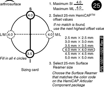
A drill guide just large enough to circumscribe the articular cartilage lesion is selected (Fig. 33-12). Available sizes are 25, 30, and 35 mm. A guide pin is inserted to the level of the laser mark by using the drill guide centered in the articular cartilage defect (Fig. 33-13). The drill guide is removed and a cannulated drill is passed over the guide pin until it is flush with the humeral head articular surface (Fig. 33-14). A tap is advanced over the guide pin and removed (Fig. 33-15). The central screw is advanced over the guide pin until the laser mark on the screw driver is flush with the articular surface of the humeral head (Fig. 33-16). The guide pin is removed and the central hole of the screw is cleaned with the taper cleaner (Fig. 33-17). A trial cap is inserted and should be at or below the level of the articular cartilage (Fig. 33-18). If the trial cap is prominent, it is removed, the screw is advanced half a revolution, and the position of the trial cap is rechecked. The centering shaft is placed in the central hole of the screw, and measurements are made with the specially designed measurement contact probe at the superior, inferior, medial, and lateral margins (Fig. 33-19) and recorded on the sizing card (Fig. 33-20). Selection of implant diameter is based on the measurements recorded on the sizing card, and the maximal measurement recorded is used. An example is shown in Figure 33-21. The centering shaft is removed and a guide pin is replaced in the central hole of the screw.
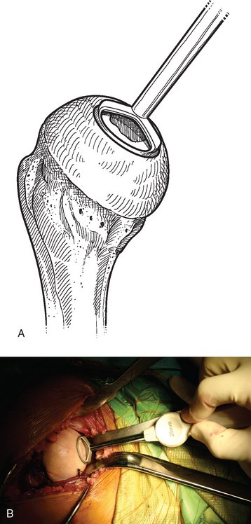
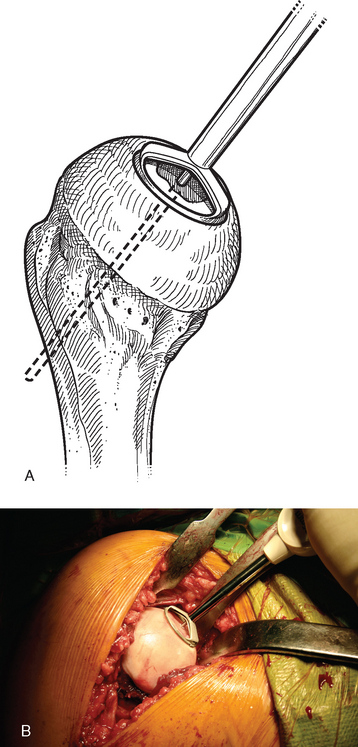
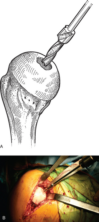
Figure 33-14 A and B, Drilling the hole for the central screw used in partial humeral head resurfacing.
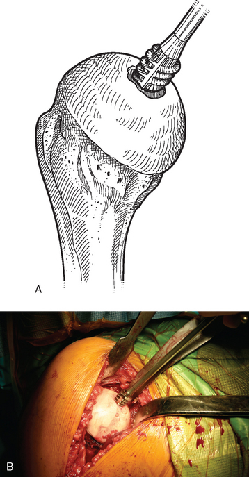
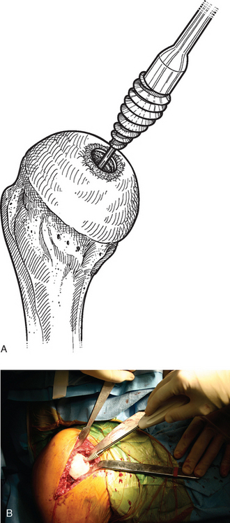
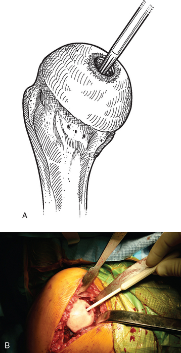
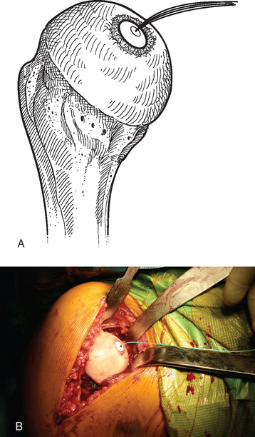
Figure 33-18 A and B, The trial cap is inserted to ensure that the central screw has been advanced sufficiently.
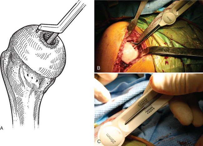
Figure 33-19 A to C, Each quadrant of the humeral head is measured with the contact probe placed over the centering shaft.
A surface reamer appropriate for the implant chosen is selected and used for reaming until it contacts the screw (Fig. 33-22). The reamer and guide pin are removed, and the central screw hole is cleaned with the taper cleaner. The appropriate sizing trial is placed in the central screw hole to ensure that the final implant will not be prominent (Fig. 33-23). The edges of the trial implant should be flush or slightly recessed with respect to the surrounding intact articular surface. The trial is removed and the central screw hole cleaned with the taper cleaner. The final implant is placed onto the central screw with the suction inserter (Fig. 33-24). The inserter is removed by disconnecting the suction, and the implant is impacted into place with the impactor provided (Fig. 33-25). The glenohumeral joint is reduced.
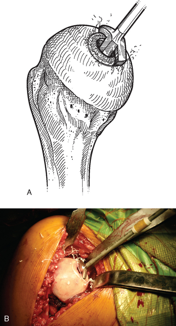
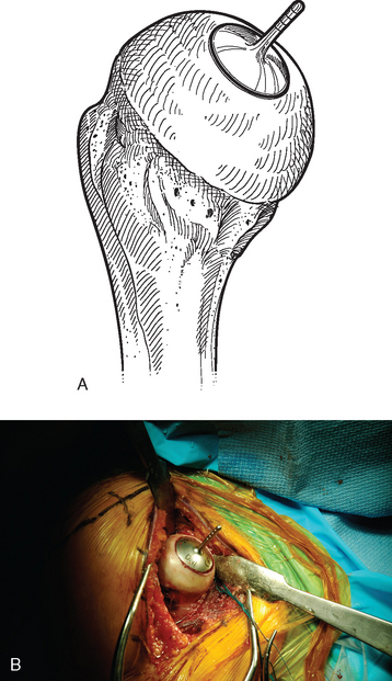
Figure 33-23 A and B, Placement of the sizing trial to ensure that the final implant will not be prominent.
TECHNIQUE FOR BIOLOGIC RESURFACING
The operating room setup, anesthesia, patient positioning, skin preparation, surgical draping, and surgical approach are identical to that for humeral surface replacement and other shoulder arthroplasties (see Chapters 3, 4, and 8). Handling of the subscapularis is the same as for prosthetic surface replacement, as described previously in this chapter. Biologic resurfacing necessitates greater preoperative planning in that it is necessary for the company supplying the proximal humeral allograft to locate an appropriately sized specimen (we use the Musculoskeletal Transplant Foundation). Magnification-controlled radiographs and computed tomography scans of the proximal humerus are provided to the allograft supplier to allow appropriate specimen selection. Our supplier has usually been able to provide specimens within 6 weeks of receiving the preoperative imaging studies. Once the specimen has been obtained, surgery is scheduled.
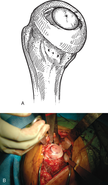
The humeral head is dislocated to expose the articular cartilage lesion (Fig. 33-26). The size of the lesion is measured with a templating device from the instrumentation set (Arthrex, Inc., Naples, FL) (Fig. 33-27), and a guide pin is placed in the humeral head at the center of the articular cartilage lesion with the templating device used as a guide (Fig. 33-28). A specialized cannulated drill is used to score the periphery of the lesion (Fig. 33-29), and a cannulated triflange reamer is used to create an osseous defect in which to place the osteochondral allograft (Fig. 33-30). If associated osteonecrosis is present in addition to the articular cartilage lesion, the reamer is advanced to a depth sufficient to eliminate the necrotic bone as determined on preoperative imaging studies. If no or minimal osteonecrosis is present, the reamer is advanced a minimum of 10 mm deep to provide an adequate interference fit for the osteochondral allograft. Figure 33-31 shows the humerus after reaming has been completed.
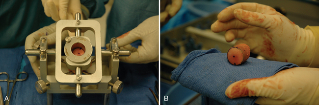
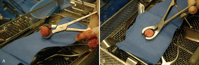
The proximal humeral allograft is positioned in the cutting jig, and the selected donor site is marked with a surgical marker (Fig. 33-32). A cutting guide of appropriate diameter is assembled onto the cutting jig, and a coring drill is used to harvest the osteochondral allograft plug (Fig. 33-33). The allograft plug is placed in a specialized clamp, and a saw is used to trim the deep surface of the allograft to match the depth penetrated by the triflange reamer (Fig. 33-34). The bone plug is progressively impacted into the prepared humeral defect until it is fully seated (Fig. 33-35).
[/level-membership-for-orthopaedics-category][not-level-membership-for-orthopaedics-category]
CHAPTER 33 Humeral Surface Replacement
The advantage of complete surface replacement of the humeral head lies mainly in preservation of subchondral bone.1 In our practice, few situations exist in which complete surface replacement of the humeral head is more advantageous than conventional humeral head replacement with a stemmed implant. Additionally, use of these surface replacement implants hinders glenoid exposure and thus prevents implantation of a prosthetic glenoid implant in many cases.
INDICATIONS AND CONTRAINDICATIONS
Complete Surface Replacement
We rarely perform complete surface replacement of the humeral head in our practice. As detailed in Chapter 6, we perform glenoid resurfacing in most shoulder arthroplasty candidates with an indication other than acute fracture. The most common indication for which we will use a complete humeral surface replacement is early-stage humeral head osteonecrosis in an active patient younger than 50 years in whom the segment of necrotic bone is sufficiently small that it will not jeopardize implant fixation, typically less than 25% of the humeral head. An additional indication is an exceptionally young, otherwise healthy patient who is a candidate for shoulder arthroplasty. Most of our patients falling into this category have chondrolysis of the glenohumeral joint after an arthroscopic instability procedure. In these cases we will consider use of a complete humeral head surface replacement combined with biologic resurfacing of the glenoid (see Chapter 34).
In addition to the standard contraindications to unconstrained shoulder arthroplasty (see Chapter 6), any condition jeopardizing implant fixation is a contraindication to humeral head surface replacement (i.e., proximal humeral fracture, extensive proximal humeral osteonecrosis). Moreover, insertion of a standard polyethylene glenoid component is a relative contraindication to use of a humeral head surface replacement, and in the vast majority of cases a conventional stemmed humeral implant should be used instead. As detailed in Chapter 10, glenoid exposure is the most important portion of prosthetic glenoid resurfacing, and preservation of a portion of the humeral head should never be favored over optimal glenoid exposure. Conversely, biologic resurfacing typically does not involve correction of glenoid deformity and does not entail the use of a pegged or keeled glenoid component. These concessions usually make biologic glenoid resurfacing possible with the more limited glenoid exposure available during humeral head resurfacing.
Partial Surface Replacement
Partial surface replacement is indicated in patients with localized full-thickness defects of the articular cartilage of the humeral head who have failed other treatments. When patients with full-thickness articular cartilage lesions of the humeral head are seen in our practice, we initially treat them nonoperatively with nonsteroidal anti-inflammatory medications, selective rest, and activity modification for a period of 6 to 12 weeks. If such treatment proves unsuccessful, we offer arthroscopic treatment of the lesion with débridement and drilling of subchondral bone to stimulate the formation of fibrocartilage. If patients remain symptomatic 6 months after arthroscopic treatment, we will offer them partial surface replacement. In patients older than 30 years, we opt for prosthetic replacement with a metallic device (Hemicap, Arthrosurface, Inc., Franklin, MA). In younger patients, we opt for matched osteochondral allograft replacement. In our experience, it is rare for a patient to fail arthroscopic treatment of these localized articular cartilage lesions, thus minimizing the indications for partial surface replacement.
Contraindications specific to partial surface replacement include cartilaginous lesions larger than 35 mm in diameter (the diameter of the largest implant available), the presence of nonlocalized disease (Fig. 33-1), and the absence of sufficient bone quality to support the implant.
TECHNIQUE FOR PROSTHETIC RESURFACING
The operating room setup, anesthesia, patient positioning, skin preparation, surgical draping, and surgical approach are identical to that for humeral surface replacement and other shoulder arthroplasties (see Chapters 3, 4, and 8). The first difference in the technique involves handling of the anterior humeral circumflex vessels and subscapularis. When performing humeral surface replacement, we prefer to leave the anterior humeral circumflex vessels intact to maintain optimal blood flow to the humeral head. Consequently, after placing stay sutures in the subscapularis tendon as for unconstrained shoulder arthroplasty, we end our subscapularis tenotomy just superior to the anterior humeral circumflex vessels (Fig. 33-2). Subscapularis and capsular release is rarely necessary in patients undergoing humeral surface replacement. Next, the humeral head is dislocated by externally rotating and extending the arm. Hohmann retractors are placed circumferentially around the humeral head to complete the proximal humeral exposure (Fig. 33-3).
Figure 33-3 A and B, Completed proximal humeral exposure for surface replacement of the humeral head.
Complete Surface Replacement
For complete surface replacement, we use a system (Tornier, Inc., Stafford, TX) that allows the same 12 different humeral head sizes available for stemmed unconstrained arthroplasty. We believe that selection of the appropriate humeral head size is no less important in humeral surface replacement than in stemmed humeral arthroplasty. After exposure of the humeral head is complete and peripheral humeral osteophytes are removed, the size of the humeral head is determined with the sizing guides (Fig. 33-4). If the native humeral head is between two sizes, the smaller size is selected. The pin guide corresponding to the selected humeral head size is centered over the humeral articular surface (Fig. 33-5). The guide pin is drilled into the proximal humerus through the cannulated pin guide until it engages the lateral humeral cortex (Fig. 33-6). The pin guide is removed and the guide pin left in place (Fig. 33-7
[/not-level-membership-for-orthopaedics-category]
