[level-membership-for-orthopaedics-category]
CHAPTER 20 Humeral Prosthetic Positioning
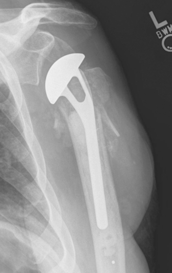
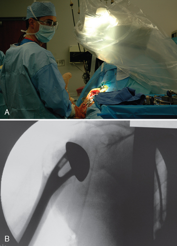
Humeral prosthetic positioning remains the most difficult step in performing unconstrained shoulder arthroplasty for fracture. Placing the humeral component excessively proud or in excessive retroversion may result in loss of fixation and subsequent migration of the greater tuberosity (Figs. 20-1 and 20-2). The complication of tuberosity migration has been found to be a key factor in poor results after unconstrained shoulder arthroplasty performed for the treatment of proximal humeral fractures.1 This chapter details humeral prosthetic positioning with each of the techniques described in Chapter 18.
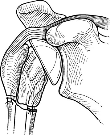
Figure 20-1 Placement of the humeral prosthesis excessively proud can result in loss of greater tuberosity fixation.

IDENTIFICATION AND PREPARATION OF THE HUMERAL DIAPHYSIS
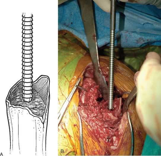
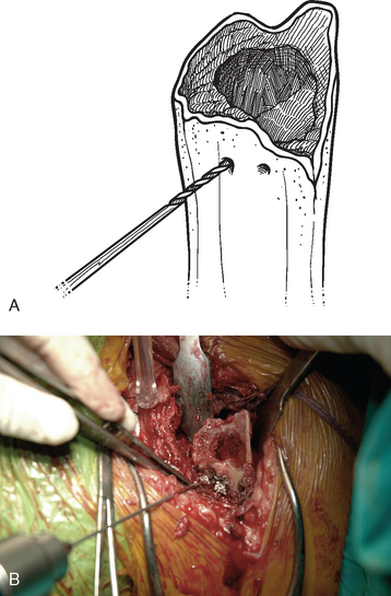
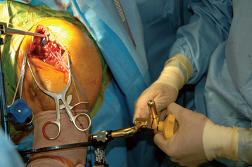
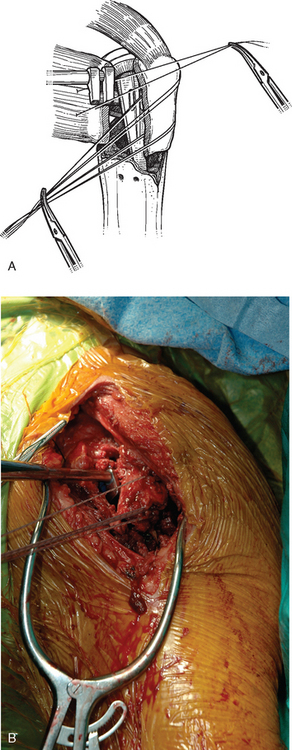
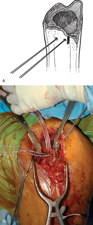
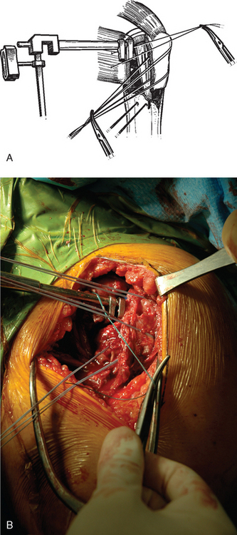
After control of both tuberosities has been achieved, the humeral shaft is identified. The humeral shaft is progressively reamed until the reamer that is used corresponds to the diameter of the prosthesis to be implanted (Fig. 20-3). Using the largest diaphyseal reamer that is possible to advance down the humeral canal without difficulty avoids selecting too small a diameter of the humeral implant, which can inadvertently be positioned in valgus or varus (Fig. 20-4). Because most of these patients are severely osteopenic, however, no effort is made to force too large a reamer down the humeral canal for fear of iatrogenic fracture. The bicipital groove is located and two 2-mm holes are drilled in the humeral shaft approximately 1 cm distal to the fracture site, one on each side of the bicipital groove, for use later in tuberosity fixation (Fig. 20-5). The intra-articular portion of the long head of the biceps, which is frequently at least partially torn, is excised, and suture tenodesis of the remaining stump to the pectoralis major tendon is carried out with no. 1 nonabsorbable braided suture in a figure-of-eight stitch as described in Chapter 5.2
SELECTION OF THE HUMERAL IMPLANT
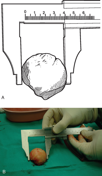
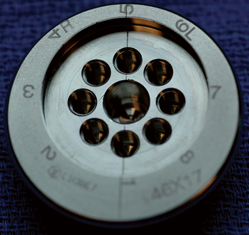
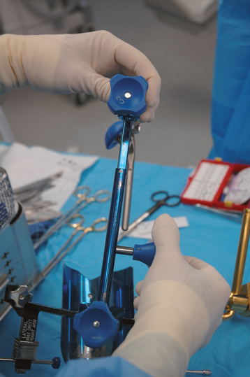
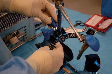
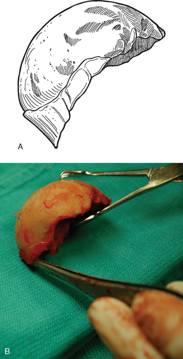
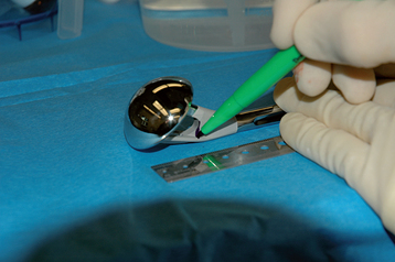
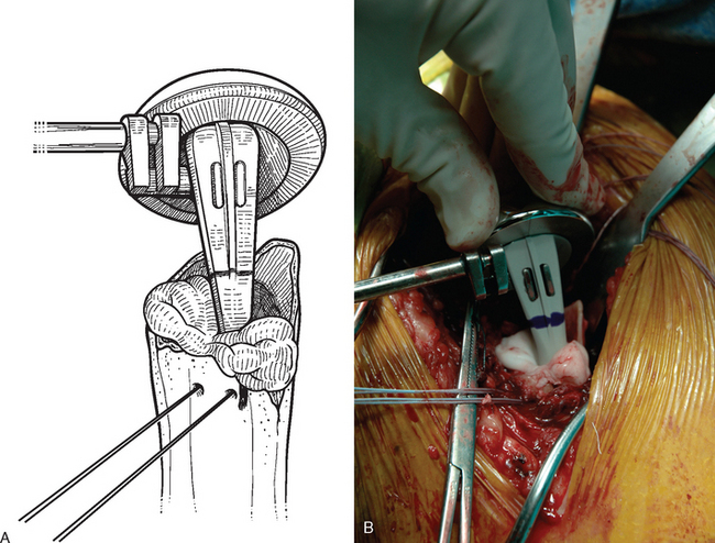
The trial humeral implant is then assembled by selecting a stem with a diameter corresponding to the largest diaphyseal reamer used and a head size corresponding to the size of the removed head fracture fragment. The humeral head fragment is usually slightly ovoid and has a lesser and greater diameter. A head size corresponding to the lesser diameter is selected to avoid insertion of too large a component, which can lead to nonunion of the tuberosities (Fig. 20-6). The prosthetic system that we use allows variation of the posterior and medial offset of the humeral head seen in normal anatomy. The “R” and “L” positions correspond to the average anatomic posterior and medial offset of a given head size for a right and left shoulder, respectively (Fig. 20-7). The variable offset is set to the “R” or “L” position, depending on whether surgery is being performed on the right or left shoulder. Once selected, the trial implant is attached to the prosthetic holder (Fig. 20-8).
PROSTHETIC POSITIONING WITH ANCILLARY INSTRUMENTATION—THE FRACTURE JIG TECHNIQUE
Placement of the prosthesis at the correct height and version remains one of the most difficult challenges when performing shoulder arthroplasty for fracture. Use of ancillary instrumentation enhances the surgeon’s ability to place the prosthesis at the correct height and in the correct amount of retroversion. The fracture jig references the humeral epicondyles to allow intraoperative estimation of proper prosthetic height and retroversion. More importantly, the fracture jig permits trial reduction of the glenohumeral joint and reduction of the tuberosities before final cementation of the humeral implant, thereby allowing adjustment of prosthetic position.
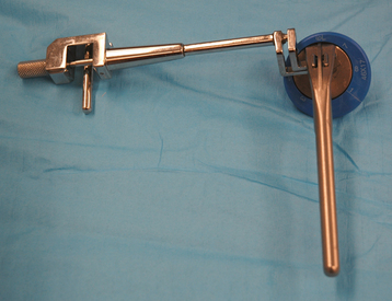
Selection of appropriate humeral height is initiated preoperatively by evaluating the length of the uninjured humerus from the superior aspect of the greater tuberosity to the transepicondylar axis radiographically, as described in Chapter 18. This measurement provides an estimated height at which to set the fracture jig during the procedure (Fig. 20-9). Appropriate humeral retroversion is provided by the protractor component of the fracture jig and is usually between 20 and 30 degrees relative to the transepicondylar humeral axis (Fig. 20-10).
After diaphyseal preparation is complete, the fracture jig is applied. The arm and forearm component is secured to the patient with a disposable elastic bandage while taking care to ensure that the patient’s extremity is well seated in the device (Fig. 20-11). The selected trial stem is connected to the remainder of the fracture jig. The fracture jig’s height is initially based on preoperative radiographs of the contralateral humerus, and the retroversion is set at 25 degrees. The trial stem is placed in the humeral shaft, and the two portions of the fracture jig (the portion attached to the stem and the portion attached to the patient) are linked but not tightened (Fig. 20-12). The glenohumeral joint is reduced, and the surgeon positions the epicondylar pads of the fracture jig over the medial and lateral humeral epicondyles (Fig. 20-13). When the surgeon is satisfied with the position of the fracture jig, an assistant tightens the linking bar to secure the position of the prosthesis (Fig. 20-14).
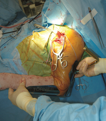
Figure 20-11 The arm and forearm component of the fracture jig is applied to the patient’s upper extremity.
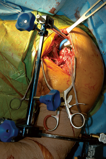
Figure 20-12 The trial stem is placed in the humeral shaft and the two portions of the fracture jig are linked but not tightened.
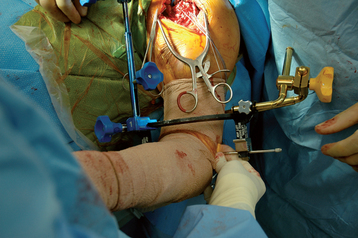
Figure 20-13 The surgeon positions the epicondylar pads of the fracture jig over the medial and lateral humeral epicondyles.
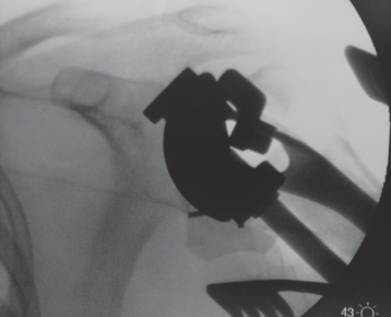
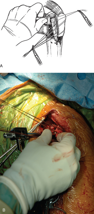
After the linking bar of the fracture jig has been tightened, minor adjustments can be made in prosthetic position based on intraoperative observations. Measurements made from preoperative radiographs provide guidelines but should not be followed blindly. Although theoretically the preoperative measurements should be very accurate, anatomic factors such as soft tissue interposed between the fracture jig and osseous reference points introduce some inaccuracies. The preoperatively measured height provides a starting point for establishing prosthetic positioning but must usually be adjusted in accordance with intraoperative observations. Helpful anatomic landmarks for establishing correct prosthetic height are the superior medial aspect of the humeral shaft and the inferior medial aspect of the humeral head fracture fragment. The amount of nonarticular surface attached to the inferior medial aspect of the humeral head fragment can be noted and a similar gap left between the inferior aspect of the humeral head component and the superior medial aspect of the native humeral shaft (Fig. 20-15). Also helpful is reduction of the greater and lesser tuberosities around the trial prosthesis to judge prosthetic height. The tuberosities should be readily reducible to the humeral diaphysis (Fig. 20-16). Adjustment of the height setting on the fracture jig is based on these observations. We have attempted to use intraoperative fluoroscopy with this technique; however, the abundance of metallic artifact introduced by the fracture jig prohibits reproducible use of image-assisted prosthetic positioning (Fig. 20-17).
PROSTHETIC POSITIONING WITHOUT ANCILLARY INSTRUMENTATION—THE GOTHIC ARCH TECHNIQUE
An alternative to the fracture jig technique is the Gothic arch technique.3 In this technique, prosthetic height is based on preoperative planning, as described in Chapter 18. With these calculations the position on the humeral trial implant that should correspond to the position of the medial aspect of the fracture is marked (Fig. 20-18). The trial humeral implant is placed in the humeral canal at the desired height with the prosthetic holder. Humeral retroversion is set between 20 and 30 degrees by judging the angle formed by the prosthetic holder and the forearm (Fig. 20-19). The glenohumeral joint is reduced while the trial implant is held at the desired height and version with the prosthetic holder. The humeral head should be directed into the center of the glenoid fossa with the arm held in neutral rotation. Once proper version is determined, an electrocautery is used to mark the position of the prosthetic fin on the humeral diaphysis (Fig. 20-20). An assistant can reduce the tuberosities around the trial implant, thereby further confirming appropriate prosthetic position (Fig. 20-21). Finally, intraoperative fluoroscopy can be used to help confirm appropriate prosthetic position. Because the plastic trial humeral head is radiolucent, we use the actual humeral implant when judging prosthetic position with fluoroscopy (Fig. 20-22). Once prosthetic position is found acceptable, the implant is removed, the appropriate height is marked on the implant, and the humeral implant is attached to the prosthetic holder (Fig. 20-23).
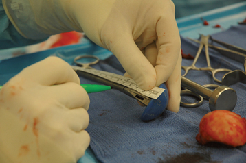
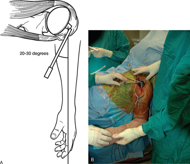
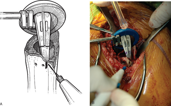
Figure 20-20 A and B, Once proper version is determined, the diaphysis is marked with an electrocautery.
IMPLANTATION OF THE HUMERAL COMPONENT
A cement restrictor is placed in the humeral canal to create a 1-cm distal cement mantle (Fig. 20-24). Two strands of no. 2 nonabsorbable braided suture are passed in an outside-to-inside direction through one of the holes previously drilled in the humeral shaft adjacent to the bicipital groove. These sutures are then passed from inside to outside though the other hole previously drilled in the humeral shaft adjacent to the bicipital groove (Fig. 20-25). The humeral canal is irrigated and dried thoroughly. Bone cement (we prefer to use DePuy 2 bone cement [DePuy, Inc., Warsaw, IN] because of its accelerated curing time of less than 8 minutes) is mixed and introduced into the humeral shaft with a catheter tip syringe.
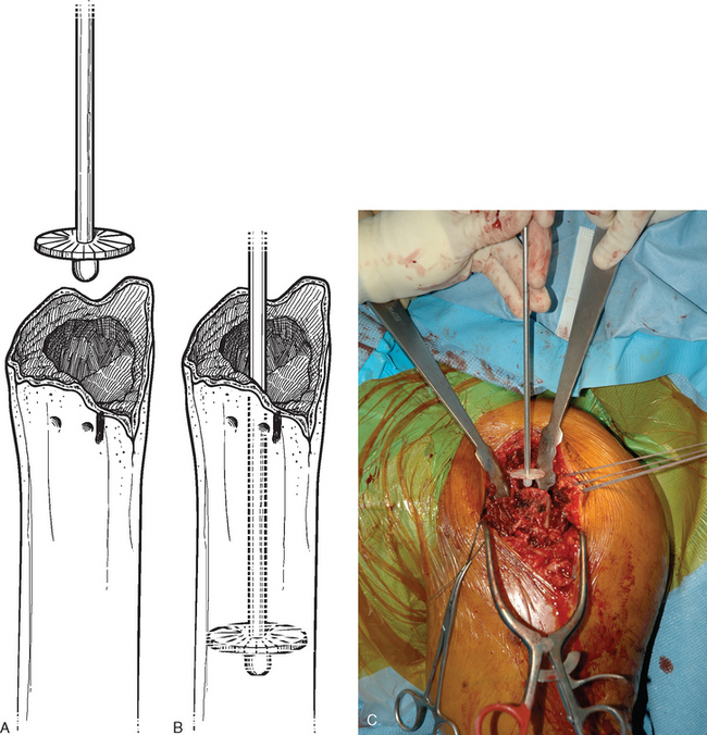
Figure 20-24 A to C, Placement of a diaphyseal cement restrictor to create a 1-cm distal cement mantle.
With the fracture jig technique, the humeral implant attached to the prosthetic holding arm is inserted into the humeral shaft, and the prosthetic holding arm is attached to the fracture jig. The glenohumeral joint is reduced and a trial reduction of the tuberosities is performed to ensure that prosthetic position is acceptable (Fig. 20-26). Minor adjustments can be made in prosthetic position with the fracture jig if necessary.
In the Gothic arch technique, the humeral implant attached to the prosthetic holder is introduced into the humeral shaft to the appropriate level marked on the implant and at the version marked on the humeral diaphysis (Fig. 20-27). The position of the prosthesis is continually checked to ensure that no movement occurs as the cement cures.
1 Boileau P, Coste JS, Ahrens PM, Staccini P. Prosthetic shoulder replacement for fracture: Results of the multicentre study. In: Walch G, Boileau P, Molé D, editors. 2000 Prosthèses d’Epaule … Recul de 2 à 10 Ans. Paris: Sauramps Medical; 2001:561-578.
2 Dines D, Hersch J: Long head of the biceps lesions after shoulder arthroplasty. Paper presented at the 8th International Congress on Surgery of the Shoulder, April 2001, Cape Town, South Africa.
3 Krishnan SG, Pennington SD, Burkhead WZ, Boileau P. Shoulder arthroplasty for fracture: Restoration of the “gothic arch”. Tech Shoulder Elbow Surg. 2005;6:57-66.
[/level-membership-for-orthopaedics-category][not-level-membership-for-orthopaedics-category]
CHAPTER 20 Humeral Prosthetic Positioning
Humeral prosthetic positioning remains the most difficult step in performing unconstrained shoulder arthroplasty for fracture. Placing the humeral component excessively proud or in excessive retroversion may result in loss of fixation and subsequent migration of the greater tuberosity (Figs. 20-1 and 20-2). The complication of tuberosity migration has been found to be a key factor in poor results after unconstrained shoulder arthroplasty performed for the treatment of proximal humeral fractures.1 This chapter details humeral prosthetic positioning with each of the techniques described in Chapter 18.
Figure 20-1 Placement of the humeral prosthesis excessively proud can result in loss of greater tuberosity fixation.
IDENTIFICATION AND PREPARATION OF THE HUMERAL DIAPHYSIS
After control of both tuberosities has been achieved, the humeral shaft is identified. The humeral shaft is progressively reamed until the reamer that is used corresponds to the diameter of the prosthesis to be implanted (Fig. 20-3). Using the largest diaphyseal reamer that is possible to advance down the humeral canal without difficulty avoids selecting too small a diameter of the humeral implant, which can inadvertently be positioned in valgus or varus (Fig. 20-4). Because most of these patients are severely osteopenic, however, no effort is made to force too large a reamer down the humeral canal for fear of iatrogenic fracture. The bicipital groove is located and two 2-mm holes are drilled in the humeral shaft approximately 1 cm distal to the fracture site, one on each side of the bicipital groove, for use later in tuberosity fixation (Fig. 20-5). The intra-articular portion of the long head of the biceps, which is frequently at least partially torn, is excised, and suture tenodesis of the remaining stump to the pectoralis major tendon is carried out with no. 1 nonabsorbable braided suture in a figure-of-eight stitch as described in Chapter 5.2
SELECTION OF THE HUMERAL IMPLANT
The trial humeral implant is then assembled by selecting a stem with a diameter corresponding to the largest diaphyseal reamer used and a head size corresponding to the size of the removed head fracture fragment. The humeral head fragment is usually slightly ovoid and has a lesser and greater diameter. A head size corresponding to the lesser diameter is selected to avoid insertion of too large a component, which can lead to nonunion of the tuberosities (Fig. 20-6). The prosthetic system that we use allows variation of the posterior and medial offset of the humeral head seen in normal anatomy. The “R” and “L” positions correspond to the average anatomic posterior and medial offset of a given head size for a right and left shoulder, respectively (Fig. 20-7). The variable offset is set to the “R” or “L” position, depending on whether surgery is being performed on the right or left shoulder. Once selected, the trial implant is attached to the prosthetic holder (Fig. 20-8).
PROSTHETIC POSITIONING WITH ANCILLARY INSTRUMENTATION—THE FRACTURE JIG TECHNIQUE
Placement of the prosthesis at the correct height and version remains one of the most difficult challenges when performing shoulder arthroplasty for fracture. Use of ancillary instrumentation enhances the surgeon’s ability to place the prosthesis at the correct height and in the correct amount of retroversion. The fracture jig references the humeral epicondyles to allow intraoperative estimation of proper prosthetic height and retroversion. More importantly, the fracture jig permits trial reduction of the glenohumeral joint and reduction of the tuberosities before final cementation of the humeral implant, thereby allowing adjustment of prosthetic position.
Selection of appropriate humeral height is initiated preoperatively by evaluating the length of the uninjured humerus from the superior aspect of the greater tuberosity to the transepicondylar axis radiographically, as described in Chapter 18. This measurement provides an estimated height at which to set the fracture jig during the procedure (Fig. 20-9). Appropriate humeral retroversion is provided by the protractor component of the fracture jig and is usually between 20 and 30 degrees relative to the transepicondylar humeral axis (Fig. 20-10).
[/not-level-membership-for-orthopaedics-category]
