CHAPTER 12 Glenoid Component
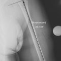
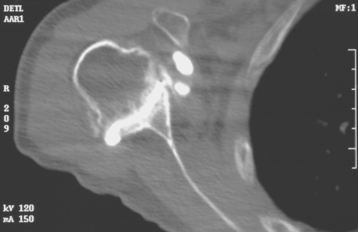
Historically, the glenoid component has been the “weak link” of shoulder replacement. In addition to being the most difficult part of the surgical procedure, the glenoid component is the most likely site of component failure, which has led many surgeons to avoid glenoid resurfacing in nearly all cases. Fortunately, glenoid component materials and designs have improved greatly, as have techniques for implantation of glenoid components. Problems with the glenoid component are becoming less common, perhaps leading more surgeons to consider glenoid resurfacing in more cases. As detailed in Chapter 6, we prefer to implant a glenoid component in most nonfracture indications for unconstrained shoulder arthroplasty because of results superior to those of hemiarthroplasty in most diagnoses. The main contraindication to glenoid resurfacing in patients with a competent rotator cuff is insufficient glenoid bone to support implantation of a glenoid component. Such cases are readily identifiable with preoperative imaging studies (Fig. 12-1).
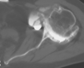
Figure 12-1 Case involving insufficient glenoid bone stock to allow implantation of a glenoid component.
The steps involved in implantation of the glenoid component include obtaining glenoid exposure (detailed in Chapter 10), reaming the glenoid surface, selecting the size of glenoid component to be implanted, selecting the type of glenoid component to be implanted, preparing the native glenoid bone for implantation of the glenoid component, and final implantation of the glenoid component. Each facet of this process is detailed in this chapter.
REAMING THE GLENOID SURFACE
Reaming the glenoid surface serves two purposes: first, it provides a congruent surface that matches the apposing surface of the implant by removing any remaining cartilage and smoothing the osseous surface, and second, it corrects any deformity caused by bony wear, as identified on preoperative imaging (Fig. 12-2). If no deformity is present, “light” reaming is performed. In patients with posterior glenoid wear, however, the anterior portion of the glenoid should be preferentially reamed to correct the deformity.
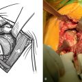
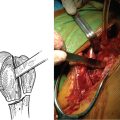
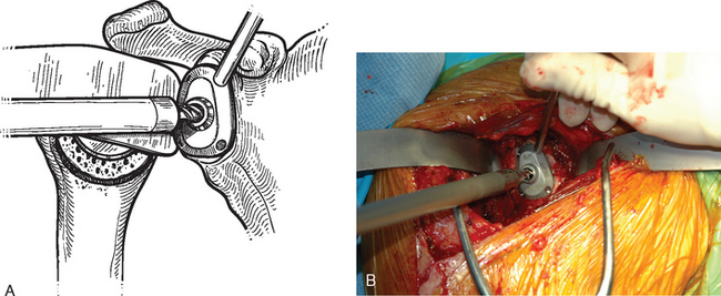
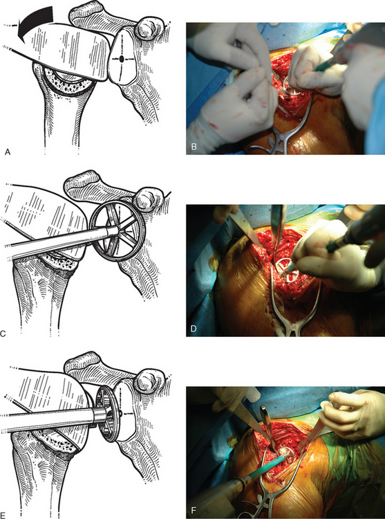
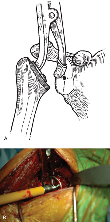
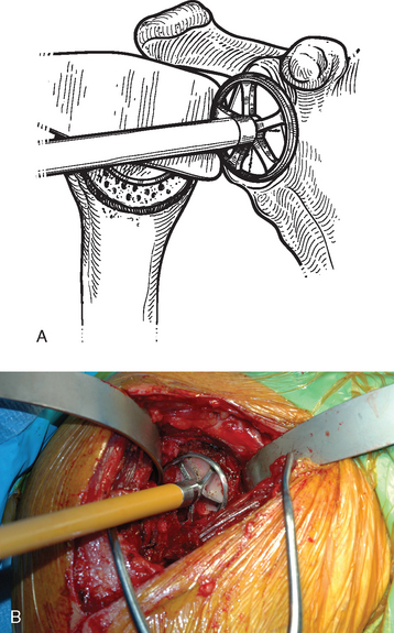
After humeral preparation and insertion of the humeral cut protector (Chapter 11), the humeral head retractor is replaced to retract the proximal humerus posteriorly and expose the glenoid (Fig. 12-3). It is helpful to mark the center point of the glenoid with an electrocautery. It is also important to realize that with severe deformity or biconcavity, the center point will change (the new center point is posterior to the original center point after “reaming away” a portion of the anterior glenoid) by preferentially reaming the anterior glenoid, and this should be considered when identifying the center point. A guide with a stop is used when drilling a pilot hole through the center point of the glenoid (Fig. 12-4). The tip of a reamer of the appropriate glenoid size (see the next section) is introduced into the pilot hole (Fig. 12-5). Introduction of the reamer is usually the most difficult part of glenoid resurfacing. A few techniques are helpful when performing this portion of the procedure in exceptionally stiff shoulders. We first confirm with the anesthesiologist that the patient is adequately relaxed with paralytic agents. We then determine which posterior glenoid retractor yields the best exposure. We start with the Trillat humeral head retractor. If this proves inadequate, we will also try a Fukada humeral head retractor, a large glenoid rim retractor, or one or more Hohmann retractors (these retractors are shown in Chapter 3). Many times it is necessary for the assistant retracting the humeral head to perform a maneuver with the humeral head retractor to facilitate insertion of the reamer. This is done by first forcefully retracting posteriorly and then relaxing the retractor to allow clearance of the posterior aspect of the reamer. The retractor can be left in place in a relaxed position during the actual reaming. This technique is illustrated in Figure 12-6. Rarely, despite the use of these techniques for exposure of the glenoid and insertion of the reamer, it may not be possible to insert the reamer tip into the pilot hole. In this scenario we remove the humeral head retractor completely and insert a laminar spreader between the glenoid and humerus. One limb of the laminar spreader is placed at the most superior aspect of the glenoid surface, and the other limb is placed on the cut surface of the proximal humerus. The laminar spreader is opened to distract the glenohumeral joint and retract the humerus laterally. This technique allows insertion of the glenoid reamer by eliminating obstruction of the reamer by the posterior humeral head retractor (Fig. 12-7). By using these techniques sequentially, we have yet to perform a shoulder arthroplasty in which we were unable to resurface the glenoid because of inadequate exposure.
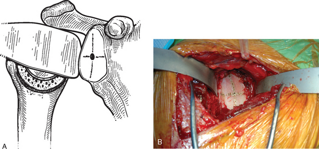
Figure 12-3 Glenoid exposure. The center point of the glenoid has been marked with the electrocautery.
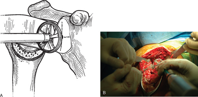
After the tip of the reamer is inserted into the pilot hole, the cutting surface of the reamer is slightly distracted away from the glenoid surface as the reamer is started. This helps avoid glenoid fracture by preventing the reamer from suddenly engaging any prominent areas on the glenoid. The reamer is advanced medially to engage the glenoid bone (Fig. 12-8). In patients with a concentric glenoid (identified on preoperative computed tomography or magnetic resonance imaging; Chapter 7), reaming is performed only until a surface matching the radius of curvature of the reamer (same radius of curvature as on the back side of the glenoid component) is obtained. Any remaining glenoid cartilage should be removed; however, it is unnecessary to ream past the subchondral bone to cancellous bone.
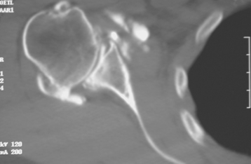
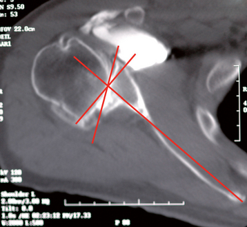
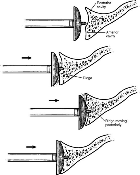
Cases of asymmetric glenoid wear represent a challenging problem. This wear is almost always posterior in primary osteoarthritis and creates a biconcave glenoid with the humeral head articulating with the posterior concavity (Fig. 12-9). This biconcavity may not be grossly apparent during surgical visualization, hence the need for adequate preoperative imaging studies (Chapter 7). In addition to providing a concentric surface for the glenoid component, an additional goal of reaming in this scenario is to eliminate the biconcave glenoid morphology and restore the glenoid to a single-concavity morphology with appropriate version (2 to 8 degrees of retroversion). Preoperative planning with computed tomography or magnetic resonance imaging helps determine the amount of correction necessary (Fig. 12-10; see Chapter 7 for more details). When reaming a biconcave glenoid, the anterior glenoid is preferentially reamed until a single concavity is achieved and the glenoid surface has been reoriented into correct version. As reaming progresses, the reamer should be periodically removed and the glenoid surface checked. A ridge on the glenoid surface demarcating the two concavities of the glenoid surface should move progressively posteriorly until it is no longer visible (Fig. 12-11).
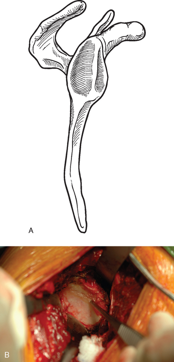
Figure 12-9 Glenoid biconcavity in primary osteoarthritis identified on preoperative computed tomography.
SELECTING THE SIZE OF THE GLENOID COMPONENT
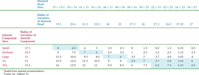
Selection of glenoid component size is based on coverage of the glenoid surface and, more importantly, on glenohumeral component mismatch. Glenohumeral prosthetic mismatch is defined as the difference in radius of curvature between the humeral head and glenoid components. Mismatch of at least 5.5 mm has been associated with fewer postoperative radiolucent lines.1 Mismatch of greater than 10 mm has been shown biomechanically to risk fracture of the polyethylene glenoid component.2 In the prosthetic system that we use, the preferred mismatch is obtained by combining a given humeral head size with a given glenoid component size (Table 12-1). The size of the humeral head is first selected as described in Chapter 11. The corresponding glenoid size is selected so that glenohumeral prosthetic mismatch is optimized. Occasionally, the native glenoid surface area is larger than the surface of the selected glenoid component. In this case a larger glenoid component is selected to provide better surface coverage and increased glenohumeral prosthetic mismatch. In the rare scenario in which the selected glenoid component is larger than the native glenoid surface, the preferentially selected glenoid component is used while some peripheral overhanging of the glenoid component is accepted to respect a mismatch of at least 5.5 mm.
SELECTING THE TYPE OF GLENOID COMPONENT
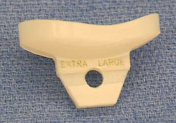
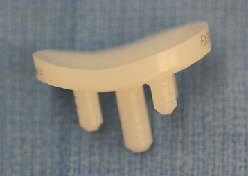
After the glenoid has been reamed and the size of glenoid component selected, the type of glenoid to be implanted is determined. We use either a keeled component or a pegged component. Both components are all-polyethylene convex-back components inserted with cement (Figs. 12-12 and 12-13). Radiographic studies have shown superior early results with pegged components.3 Laboratory biomechanical studies have favored fixation of pegged components as well.4 Clinical outcomes have been equivocal or shown slightly better results with keeled components.5 In most scenarios, we believe that selection of a keeled or pegged glenoid component is based largely on surgeon preference. In patients with a shallow glenoid vault as determined on preoperative computed tomography or magnetic resonance imaging (type A2 glenoid, see Chapter 7), we prefer a keeled component. If the glenoid vault appears inadequate to place the 15-mm keel of the implant, the tip of the keel can be shortened with a cutting rongeur (Fig. 12-14).
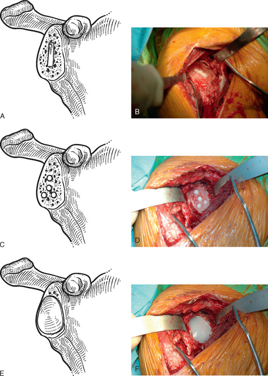
PREPARING THE GLENOID BONE
The technique used for preparing the native glenoid bone has been shown to influence the radiographic results when a keeled glenoid component has been selected.6 When implanting a keeled glenoid component we prefer using the bony compaction technique pioneered by Gazielly.7 Holes are drilled superior and inferior to the original pilot hole with use of a template device, and any remaining bony bridge is broken with a rongeur (Fig. 12-15). A keel punch that is the same size as the keel of the glenoid component is impacted into the native glenoid to finish preparation of the keel slot (Fig. 12-16). A trial glenoid component is inserted to ensure full seating of the component (Fig. 12-17). The trial component is removed and the keel slot is irrigated with sterile saline and dried with a sponge, an inexpensive technique shown to be as effective as the use of hemostatic agents and compressed carbon dioxide.8
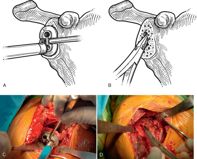
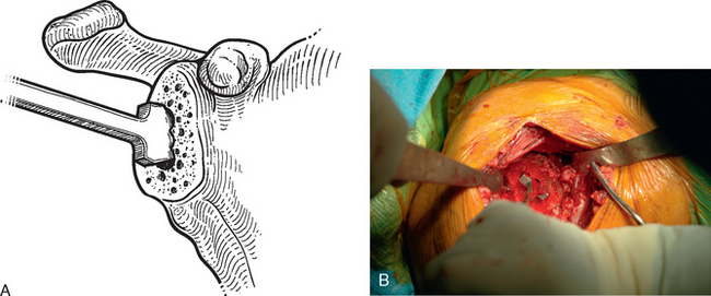
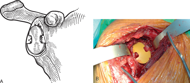
Figure 12-17 A and B, Placement of the trial glenoid component to ensure that the component fully seats.
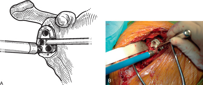
When using a pegged glenoid component, a different template is used to drill the peg holes (Fig. 12-18). The peg holes are then irrigated and dried in the same manner as described for the keel slot.
FINAL IMPLANTATION OF THE GLENOID COMPONENT
The final component is cemented in place with polymethylmethacrylate (we prefer to use DePuy 2 bone cement [DePuy, Inc., Warsaw, IN] because of its accelerated curing time of less than 8 minutes) in the keel slot/peg holes only (Fig. 12-19). An impactor impacts and holds the component in place while the cement cures.
1 Walch G, Edwards TB, Boulahia A, et al. The influence of glenohumeral prosthetic mismatch on glenoid radiolucent lines: Results of a multicentric study. J Bone Joint Surg Am. 2002;84:2186-2191.
2 Friedman RJ, An YH, Draughn RA. Glenohumeral congruence in total shoulder arthroplasty. Orthop Trans. 1997;21:17.
3 Gartsman GM, Elkousy HA, Warnock KM, et al. Radiographic comparison of pegged and keeled glenoid components. J Shoulder Elbow Surg. 2005;14:252-257.
4 Anglin C, Wyss UP, Nyffeler RW, Gerber C. Loosening performance of cemented glenoid prosthesis design pairs. Clin Biomech. 2001;16:144-150.
5 Gazielly D, El-Abiad R. Comparative results of three types of polyethylene cemented glenoid components. In: Walch G, Boileau P, Molé D, editors. 2000 Prosthèses d’Epaule … Recul de 2 à 10 Ans. Paris: Sauramps Medical; 2001:483-488.
6 Szabo I, Buscayret F, Edwards TB, et al. Radiographic comparison of two different glenoid preparation techniques in total shoulder arthroplasty. Clin Orthop Relat Res. 2005;431:104-110.
7 Gazielly DF, Allende C, Pamelin E: Results of cancellous compaction technique for glenoid resurfacing. Paper presented at the 9th International Congress on Surgery of the Shoulder, May 2004, Washington, DC.
8 Edwards TB, Sabonghy EP, Elkousy HA, et al. Glenoid component insertion in total shoulder arthroplasty: Comparison of three techniques for drying the glenoid prior to cementation. J Shoulder Elbow Surg. 2007;16(3 Suppl):S107-S110.