Gas Therapy
I Medical, Laboratory, and Therapeutic Gases and Mixtures
H Oxygen/nitrogen (21% O2/79% N2)
I Oxygen/carbon dioxide (90% to 98% O2/2% to 10% CO2)
IV Gases That Support Combustion
A Cylinder types and composition
1. Type 3AA: Seamless, high-quality, heat-treated tempered alloy-steel
2. Type 3A: Seamless, low carbon, heat-treated steel (no longer produced)
B Cylinder markings: Markings are located at the neck of the cylinder in two groupings (Figure 33-1).

a. Line 1: ICC or DOT, 3A or 3AA, 2015
(1) ICC or DOT: The organization governing the transport of cylinders
(a) ICC: Interstate Commerce Commission. The agency that regulated construction, transport, and testing of compressed gas cylinders from 1948 to 1970.
(b) DOT: Department of Transportation. The federal agency responsible for construction, transport, and testing of compressed gas cylinders since 1970.
(3) 2015: Maximum working pressure in pounds per square inch (psi), which normally can be exceeded by 10% (2200 psi).
1. Large cylinders using hexagonal nut connections (see Section VII, B, American Standard Compressed Gas Cylinder Valve Outlet and Inlet Connections Safety System index)
a. H or K: 9-in. diameter, 55-in. height
b. G: 8.5-in. diameter, 55-in. height
2. Small cylinders using yoke connections (see Section VII, A, Pin-Index Safety System)
D Cylinder capacities for oxygen
E Maximum filling pressure of 3AA oxygen cylinders: 2015 psi plus 10% (2200 psi)
F Calculation of duration of flow from oxygen and compressed air cylinders
1. One cubic foot of gas = 28.3 L
2. The volume of gas in liters in a full cylinder = cubic foot volume × 28.3 L/ft3
3. Dividing the aforementioned determined value by the maximum filling pressure of 2200 psi results in the calculation of a factor indicating the number of L/psi:
< ?xml:namespace prefix = "mml" />
 (1)
(1)
5. L/psi factors for oxygen cylinders
6. Calculation of duration of flow in minutes
a. Gauge pressure multiplied by duration of flow factor (L/psi) equals the number of liters in the cylinder.
b. Dividing the result of no. 6a by the flow in L/min results in the time in minutes that the cylinder will last:
 (2)
(2)| Gauge pressure | 1500 psi |
| Duration of flow factor | 0.28 L/psi |
| Flow in L/min | 10 L/min |
The cylinder will deliver 10 L/min for 42 minutes before it is completely empty.
d. Clinically it is advisable to subtract 500 psi from the gauge pressure to provide a safety margin before the duration of flow is calculated.
G Color code for E cylinders (Color coding is mandatory for E-sized cylinders only; other sizes of cylinders are not required to follow any coding system.)
1. Oxygen: Green (universal code: white)
7. Oxygen and carbon dioxide: Green and gray
8. Oxygen and helium: Green and brown
10. Nitrogen and oxygen: Black and green (other than room air)
H Hydrostatic testing of cylinders
1. Perform periodic high-pressure testing of gas cylinder integrity.
2. Cylinder expansion is determined by measuring water displacement of an empty cylinder compared with that cylinder when filled to 5/3 of its maximum pressure.
3. All cylinders must be retested every 5 to 10 years, depending on elastic expansion of the original testing.
I Cylinder stem pop-off valves
1. Large cylinders use a frangible disk designed to rupture at a pressure within 5% of cylinder-bursting pressure.
2. Small cylinders use a fusible plug designed to melt at a temperature of 65.6° C to 76.7° C (150° F to 170° F).
J Gas cylinder storage and handling
1. Storage areas must meet National Fire Protection Association (NFPA) guidelines regarding construction materials, location, and actual structure; the area must be well ventilated, cool, and dry.
2. Only flame-resistant construction materials should be used in storage areas.
3. Full and empty cylinder areas must be separated to prevent confusion.
4. All cylinders should be restrained; usually chains are used for large cylinders, and racks are used for small cylinders.
5. All storage areas should be locked.
6. No oil- or petroleum-based lubricants should come in contact with valves, regulators, fittings, or gas hoses.
7. Soapy water should be used to detect system leaks.
8. Only regulators designed for a specific cylinder type and content should be used.
9. Valves on a cylinder should be cracked slowly before attachment of regulator to remove particulate matter from the valve and to dissipate heat of compression.
10. Damaged or unlabeled cylinders should not be used.
11. Cylinders should not be exposed to open flames or sparks and should not be subjected to temperatures >51.6° C/125° F.
12. Cylinder valves should be closed when not in use, and cylinder caps (large cylinders) should be in place during storage and transport.
13. Cylinders should only be transported in suitable containers or carts.
14. In some institutions there is a practice of transfilling small cylinders from large cylinders (which is not recommended because of the tremendous energy transfer and the potential for contamination). If this process is performed, labeling and cylinder inspection must conform to DOT standards. The Compressed Gas Association (CGA) also recommends that the supply cylinder be isolated, that calibrated pressure gauges be used on the cylinder being filled, and that the filling rate be limited to 200 L/min.
A High-pressure gas regulators
1. Regulators limit flow in a system by reducing maximum working pressure.
2. Regulators reduce cylinder pressures to a usable working pressure of ≤50 psi.
a. Cylinder pressure is reduced to a working pressure of ≤50 psi in one step or stage.
b. One high-pressure pop-off valve is incorporated in the regulator and set at approximately 200 psi.
a. Cylinder pressure is reduced to a working pressure of ≤50 psi in a series of steps or stages.
b. A high-pressure pop-off valve is incorporated into each stage of the regulator, with the final stage pop-off valve set at approximately 200 psi.
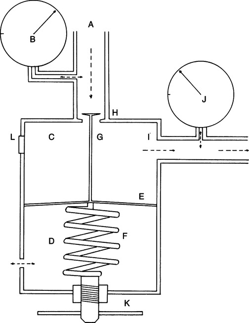
5. Preset regulators (Figure 33-2)
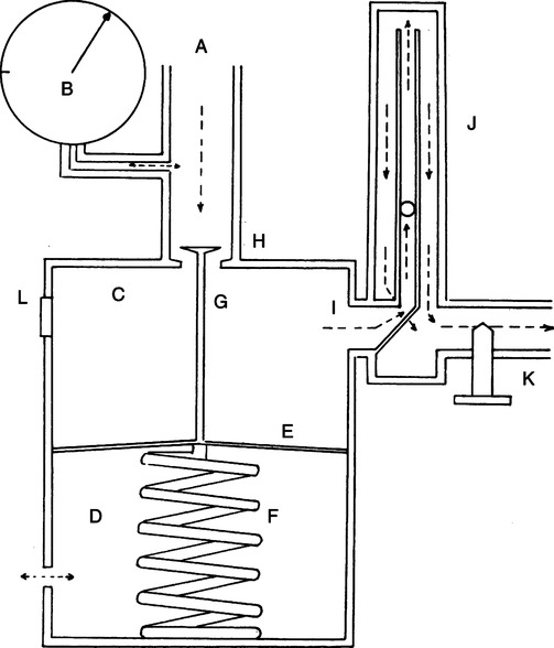
a. Pressure is reduced in one or more stages to a fixed working pressure of 50 psi.
b. Normally a low-pressure gas-regulating device (e.g., Thorpe tube) is incorporated to reduce flows to working levels.
c. Preset regulators are used without a Thorpe tube when connected to a system using a 50-psi pressure source (e.g., ventilators).
B Low-pressure gas regulators (flowmeters)
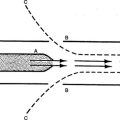
1. Bourdon gauge (Figure 33-4)
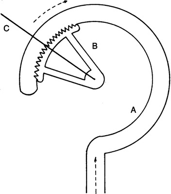
a. The Bourdon gauge is a pressure-sensitive gauge that uses an expandable copper coil to indicate pressure readings.
b. Bourdon gauges can be calibrated to indicate flow and are used as flow-measuring devices.
c. If backpressure is applied distal to the gauge, it will indicate a flow higher than actual flow (Figure 33-5).
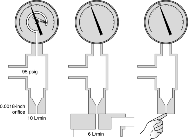
2. Orificial resistor-type flowmeters use variously sized orifices to regulate flow.
a. Currently used on small-sized cylinders to regulate gas flow
b. Only allow precise flows (i.e., 1, 2, 3, and so on) but no flows in between actual settings
c. Can be used in any orientation or position and do not affect output of gas flow
d. Actual flow through the orifice is based on the law of flow or resistance. With the driving pressure constant the size of the orifice determines the exact flow exiting the orifice.
3. Thorpe tube flowmeters (Figure 33-6): Gas flow is measured by the vertical displacement of a float in an increasing diameter tube. Flow is regulated by a needle valve placed proximal or distal to the float.
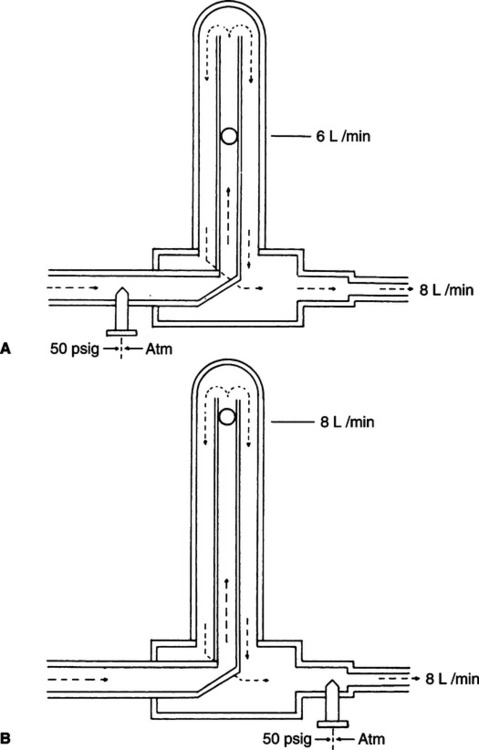
a. Compensated Thorpe tubes are designed to function accurately at a working pressure of 50 psi at 21.1° C (70° F).
(1) The needle valve is always located distal to the float.
(2) If backpressure is applied distal to the needle valve, the float will indicate the actual flow delivered.
b. Uncompensated Thorpe tubes are designed to function at variable working pressures.
VII Safety Systems Incorporated in Gas Flow Systems and Cylinders
A Pin-Index Safety System (PISS) (Figure 33-7)
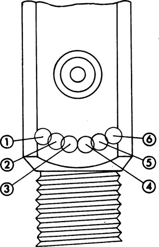
1. This system is used only on E-sized cylinders or smaller.
2. It is used on connections for which the maximum working pressure is >200 psig (pounds per square inch gauge).
3. It incorporates a yoke-type of connection where two pins on the regulator connection (yoke) are matched to holes on the cylinder stem (Figure 33-8).
4. Ten possible combinations are available; nine currently are in use.
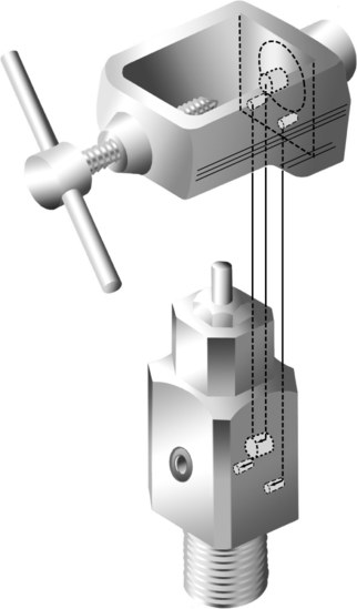
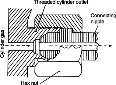
B American Standard Compressed Gas Cylinder Valve Outlet and Inlet Connections Safety System (Figure 33-9)
1. This system is only used on cylinders larger than E size.
2. It is used on connections for which the maximum working pressure is >200 psig.
3. It incorporates a hexagonal nut and specific nipple on the regulator fitted to an externally threaded cylinder connection.
4. For oxygen the connection is CGA-540, 0.903-14 NGO, RH-Ext, which indicates a CGA connection no. 540 is used with a 0.903-in. threaded outlet diameter and 14 threads/in. of the National Gas Outlet type, and the threads are external and right handed.
C Diameter-Index Safety System (DISS) (Figure 33-10)
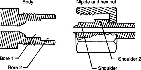
1. Used on all connections distal to the regulator for which maximum working pressures are <200 psig.
2. Used for connections of flowmeters to regulators or other connections where frequent equipment changes are made.
3. It incorporates a hexagonal nut and a nipple designed with two shoulders fitted into a body and externally threaded with two concentric borings.
4. The DISS connection for oxygen is no. 1240 with a 0.5625-in. diameter and 18 threads/in.
VIII Agencies Regulating Medical Gases
A Food and Drug Administration (FDA): Determines purity standards and labeling for all medical gases listed in the United States Pharmacopeia (USP).
B Compressed Gas Association (CGA): Sets standards and makes recommendations to manufacturers and municipal authorities on manufacture of gases and safety standards for cylinders.
C National Fire Prevention Agency (NFPA): Sets standards and makes recommendations to manufacturers and municipal authorities on storage and handling of cylinders.
D Department of Transportation (DOT): The federal agency responsible for construction, transport, and testing of compressed gas cylinders since 1970.
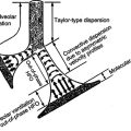
IX Fractional Distillation of Air
A The gas is filtered to remove all dust and impurities.
B The gas is dried to remove all water vapor.
C The gas is compressed to 200 atm pressure.
D The heat of compression is removed by heat exchangers until the temperature returns to ambient.
E By decreasing the pressure 5 atm the gas is then rapidly and repeatedly decompressed. The reduction in pressure allows tremendous cooling by expansion to occur, bringing the temperature below the boiling point and liquifying all gases in the air.
F The temperature of the liquid is then increased, and the various gases are evaporated and collected at their respective boiling points.
A There are three types of centrally located systems.
1. Alternating gas supply system (Figure 33-11).
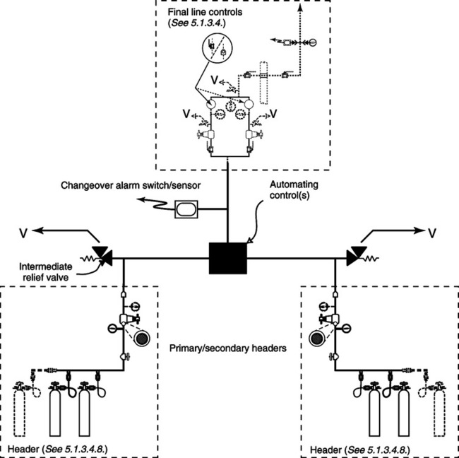
a. Consists of large cylinders of oxygen banked together in two separate series
b. These two banks are called the primary and reserve bank.
c. When the pressure of the primary bank reaches a certain level a control valve switches to the reserve supply.
d. Because the primary bank is now empty, the reserve bank becomes the primary bank. The empty cylinders are filled, and this bank is now called the reserve.
2. Gas cylinder supply system with reserve supply
a. Consists of a primary, secondary, and reserve supply system
b. Once the primary supply is empty of gas, a valve automatically switches to the secondary supply, similar to the alternating system.
c. Alarms signal when changeovers have occurred and refilling the primary and/or secondary systems is needed.
XI Bulk Liquid Oxygen Systems (Figure 33-12)
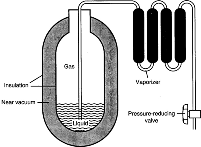
A These systems are more efficient than the gaseous systems because 1 ft3 of liquid O2 is equal to 860.6 ft3 of gaseous O2, or 24,354.98 L of O2.
B Liquid O2 must be stored below its critical temperature of −181.1° F and prevented from exerting a pressure >250 psi.
C The storage unit is composed of an inner and outer steel shell separated by an insulating vacuum to prevent transfer of heat to the liquid; the inner shell is coated with silver to aid in repelling heat. The unit is also vented to allow vaporized O2 to exit, maintaining internal pressure <250 psi. This is essentially a large thermos bottle (see Figure 33-12).
D Liquid O2 leaving the storage unit is converted to a gaseous state by a vaporizer, after which it is reduced to 50 psi for delivery into the central piping system.
E Storage areas must meet NFPA guidelines regarding construction, design, and location. Among key provisions in these standards is the requirement for a reserve or backup gas supply to equal the average daily usage of the hospital. To meet this demand, hospitals may use either a smaller liquid O2 storage tank or a bulk gas oxygen system as a backup measure.
XII Portable Liquid Oxygen Systems
A These systems are used primarily for home oxygen therapy or intrahospital transport.
B Because a larger volume of oxygen (860.6 L gas/L liquid) can be stored more easily as a liquid than as a gas, these systems are most useful for home care.
C During storage there is evaporative loss of oxygen because of the continual conversion of the liquid to a gas.
D Available oxygen flow rates are up to 8 L/min.
E These units do not provide the 50-psi power source needed to drive other respiratory care equipment.
F These units are generally stationary and can provide oxygen therapy for 4 to 12 days at 2 L/min.
G Many companies also manufacture portable liquid oxygen systems.
1. These systems contain approximately 0.5 to 1.5 L of liquid oxygen.
2. They are generally lightweight (5 to 13.5 lb).
3. Provision of oxygen at 1 L/min can be maintained for up to 24 hours with some units.
H Cylinders of liquid gases are filled to a specified filling density. Weighing a liquid-filled cylinder is the only accurate method to determine the contents of the cylinder.
I Calculating the duration of flow in minutes for liquid oxygen
1. One liter of liquid oxygen weighs 2.5 lb = 860 L of oxygen in a gaseous state.
2. Amount of gas in cylinder = (Liquid O2 weight [lb])(860)/2.5 lb/L
3. Duration of gas in minutes = Amount of gas in cylinder (L)/Flow (L/min)
a. Example of duration of flow

The cylinder will deliver 3 L/min for 172 minutes before it runs out.
A These systems incorporate molecular sieves of permeable membranes to purify entrained ambient air.
B Concentrations of 80% to 95% oxygen are generally available. The higher the delivered flow, the lower the FIO2 level.
A Large medical air compressors (Figure 33-13)
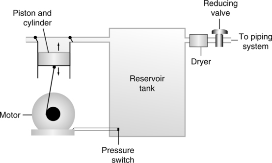
1. Used to provide high flow rates at working pressures of 50 psig
2. A motor drives a piston in a compression cylinder, which draws air in through a filtered valve into a reservoir tank. The pressure in the reservoir tank is higher than line pressure.
3. The gas leaves the reservoir and then goes through a dryer to remove the moisture and then goes through a reducing valve to bring it to line pressure.