[level-membership-for-orthopaedics-category]
CHAPTER 44 Future Directions in Shoulder Arthroplasty
Shoulder arthroplasty has advanced immeasurably since the first shoulder replacement was implanted by Péan in 1893.1 Implant designs continue to evolve and improve, as do the materials from which these designs are constructed. The reverse prosthesis has gained widespread use in the United States since 2004 and continues to evolve, with minor design changes introduced by many companies that manufacture a version of this semiconstrained device.
Our personal interest in the future of shoulder arthroplasty has focused largely on computer-assisted navigation.2,3 Computer-assisted navigation has been used successfully to improve implant alignment in hip and knee arthroplasty.4,5 We have used similar technology involving an image-free system to monitor and improve implant alignment during shoulder arthroplasty.
PREOPERATIVE PLANNING FOR NAVIGATION IN UNCONSTRAINED SHOULDER ARTHROPLASTY
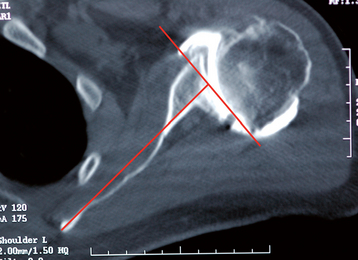
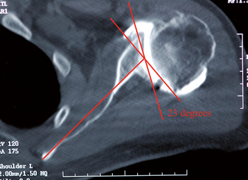
The angle of glenoid version is determined relative to the long axis of the scapula from an axial computed tomogram.6 The plane of section needed for this measurement is located in approximately the middle of the glenoid cavity and is estimated by using the first section inferior to the tip of the coracoid process. The long axis of the scapula is determined by taking the center point of the anteroposterior diameter of the glenoid and constructing a line from this point to the medial aspect of the scapula (Fig. 44-1). A reference neutral axis (0-degree version) is drawn perpendicular to the long axis of the scapula (Fig. 44-2). A line is drawn tangential to the anterior and posterior rims of the glenoid cavity (Fig. 44-3). The acute angle formed by these two lines is the angle of glenoid version (Fig. 44-4). Once version is measured, the amount of correction may be determined. Normal glenoid version ranges from 2 degrees of anteversion to 9 degrees of retroversion.6 For the example in Figures 44-1 to 44-4, the retroversion measures 23 degrees.


SURGICAL TECHNIQUE FOR NAVIGATION OF THE HUMERAL COMPONENT DURING SHOULDER ARTHROPLASTY
Room Setup
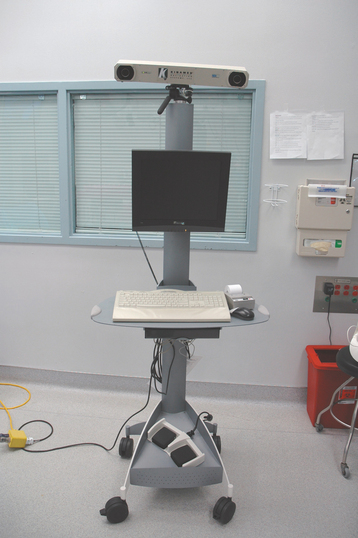
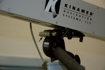
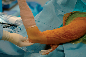
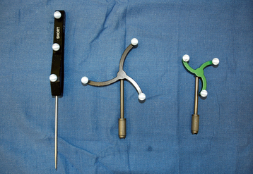
The operating room is initially set up as for nonnavigated shoulder arthroplasty. A cart containing the navigational computer with two cameras is placed at the foot of the operating table slightly on the patient’s operative side (Fig. 44-5). The camera holder is equipped with an alignment laser to ensure that the cameras are directed properly toward the operative field (Fig. 44-6). The patient is then prepared and draped as per standard technique with exception of the humeral epicondyles’ being draped free to allow use of the epicondyles as referencing points (Fig. 44-7). The three tracking instruments—a probe, a large black tracker, and a small green tracker—are placed in front of the navigational cameras and their identification by the computer verified (Fig. 44-8).
Surgical Technique
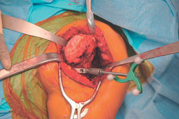
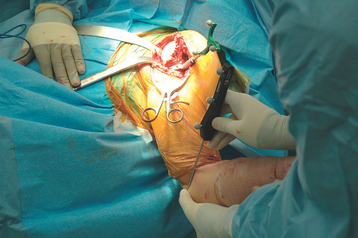
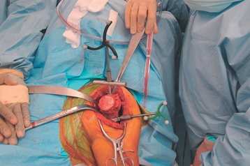
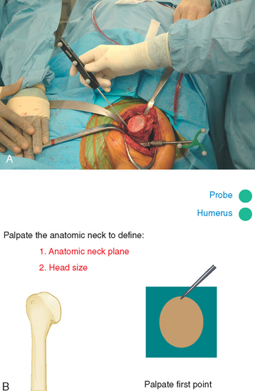
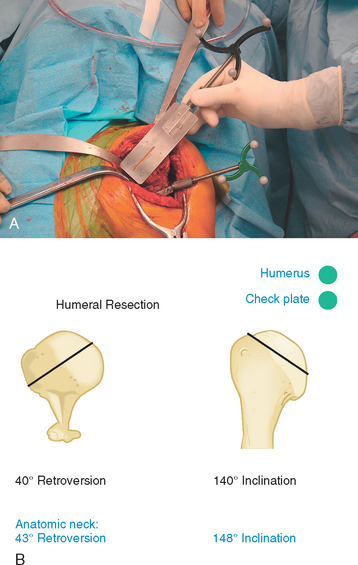
The deltopectoral surgical approach, glenoid exposure, and humeral exposure are performed in the manner previously described throughout this textbook. A clamp to hold the humeral optical tracking device (small green tracker) is secured to the anterolateral humerus with two unicortical threaded pins just distal to the humeral metaphysis (Fig. 44-9). Alternatively, a C-clamp jig can be used to hold the humeral tracking device (Fig. 44-10). After attachment of the tracking device, the probe is used to palpate the medial and lateral humeral epicondyles to create a reference line for humeral version (Fig. 44-11). The surgeon uses a foot pedal to input each data point. A navigated canal finder with the large black tracker attached is inserted into the humeral canal to create a reference axis for humeral inclination (Fig. 44-12). The humeral canal finder is removed after the axis is entered into the navigational computer. Osteophytes around the native humeral anatomic neck are removed to identify the anatomic neck of the humerus. Before resection of the humeral head, the anatomic neck axis (inclination, retroversion) and diameter are measured with the navigation system by palpating six points around the perimeter of the native humeral neck with the probe (Fig. 44-13). The humeral head is resected, and the navigation system with the large black tracker attached to a check plate is used to record inclination and retroversion of the resected plane (Fig. 44-14). The humeral tracking device is removed and humeral preparation is performed by following the technique described in Chapter 11.
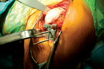
Figure 44-9 The clamp for the humeral tracker is secured to the proximal humerus with two unicortical pins.
SURGICAL TECHNIQUE FOR NAVIGATION OF THE GLENOID COMPONENT DURING SHOULDER ARTHROPLASTY
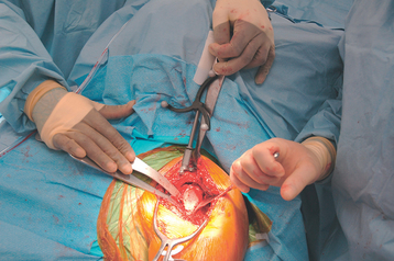
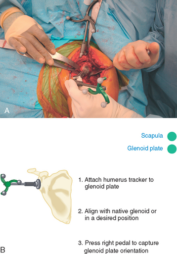
After humeral preparation, the coracoid process is exposed by placing the tip of a Hohmann-type retractor behind the base of the coracoid (Fig. 44-15). The clamp for the scapula tracker is secured to the coracoid process with two orthogonal screws (Fig. 44-16). The large black tracker is attached to the coracoid clamp (Fig. 44-17). The posterior glenoid rim retractor is placed to obtain exposure of the glenoid. A glenoid referencing instrument with the small green tracker attached is used to register version and inclination of the native glenoid surface (Fig. 44-18). In certain situations, such as excessively obese patients and those with severe glenoid deformity, it can be difficult to place the instrument flush with the glenoid surface because of limitations in exposure. To assist in these situations, the glenoid referencing instrument has a variable-angle linkage that allows the glenoid faceplate to be positioned in full contact with the native glenoid and facilitate visualization of the small green tracker by the cameras (Fig. 44-19). Once the glenoid faceplate is placed on the glenoid surface, the data are entered into the navigational computer.
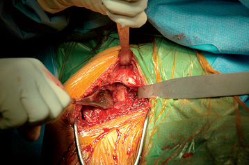
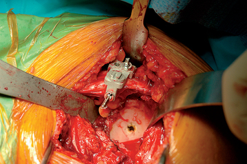
Figure 44-16 The clamp for the scapula tracker is secured to the coracoid process with two orthogonal screws.
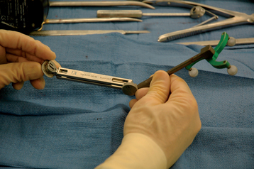
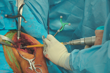
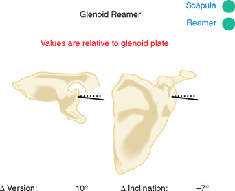
A centering hole is placed on the glenoid face as described in Chapter 12. The glenoid reamer is inserted and the small green tracker is attached to the shaft of the reamer with a special clamp (Fig. 44-20). The glenoid is reamed while the surgeon receives real-time feedback on the change in version and inclination relative to the native glenoid (Fig. 44-21). This allows the surgeon to ream the exact amount of glenoid for correction as determined from preoperative planning. For the example in Figures 44-1 to 44-4, the glenoid is corrected 20 degrees with guidance from the navigational computer. Once reaming is complete, the coracoid clamp is removed, and the remainder of the arthroplasty is completed as described in Section Two.
1 Lugli T. Artificial shoulder joint by Péan (1893). The facts of an exceptional intervention and the prosthetic method. Clin Orthop. 1978;133:215-218.
2 Sarin VK, Gartsman GM, Edwards TB: Computer-aided navigation for shoulder arthroplasty—a cadaver study. Paper presented at the 6th Annual Meeting of the International Society for Computer Assisted Orthopaedic Surgery, June 2006, Montreal.
3 Sarin VK, Pilgeram KC, Gartsman GM, Edwards TB: Computer-assisted total shoulder arthroplasty—a cadaver study. Paper presented at the 18th Annual Symposium of the International Society for Technology in Arthroplasty, September 2005, Kyoto, Japan.
4 Digioia AM3rd, Jaramaz B, Plakseychuk AY, et al. Comparison of a mechanical acetabular alignment guide with computer placement of the socket. J Arthroplasty. 2002;17:359-364.
5 Haaker RG, Stockheim M, Kamp M, et al. Computer-assisted navigation increases precision of component placement in total knee arthroplasty. Clin Orthop Relat Res. 2005;433:152-159.
6 Friedman RJ, Hawthorne KB, Genez BM. The use of computerized tomography in the measurement of glenoid version. J Bone Joint Surg Am. 1992;74:1032-1037.
[/level-membership-for-orthopaedics-category][not-level-membership-for-orthopaedics-category]
CHAPTER 44 Future Directions in Shoulder Arthroplasty
Shoulder arthroplasty has advanced immeasurably since the first shoulder replacement was implanted by Péan in 1893.1 Implant designs continue to evolve and improve, as do the materials from which these designs are constructed. The reverse prosthesis has gained widespread use in the United States since 2004 and continues to evolve, with minor design changes introduced by many companies that manufacture a version of this semiconstrained device.
Our personal interest in the future of shoulder arthroplasty has focused largely on computer-assisted navigation.2,3 Computer-assisted navigation has been used successfully to improve implant alignment in hip and knee arthroplasty.4,5 We have used similar technology involving an image-free system to monitor and improve implant alignment during shoulder arthroplasty.
PREOPERATIVE PLANNING FOR NAVIGATION IN UNCONSTRAINED SHOULDER ARTHROPLASTY
The angle of glenoid version is determined relative to the long axis of the scapula from an axial computed tomogram.6 The plane of section needed for this measurement is located in approximately the middle of the glenoid cavity and is estimated by using the first section inferior to the tip of the coracoid process. The long axis of the scapula is determined by taking the center point of the anteroposterior diameter of the glenoid and constructing a line from this point to the medial aspect of the scapula (Fig. 44-1). A reference neutral axis (0-degree version) is drawn perpendicular to the long axis of the scapula (Fig. 44-2). A line is drawn tangential to the anterior and posterior rims of the glenoid cavity (Fig. 44-3). The acute angle formed by these two lines is the angle of glenoid version (Fig. 44-4). Once version is measured, the amount of correction may be determined. Normal glenoid version ranges from 2 degrees of anteversion to 9 degrees of retroversion.6 For the example in Figures 44-1 to 44-4, the retroversion measures 23 degrees.
[/not-level-membership-for-orthopaedics-category]
