CHAPTER 132 Fusion – Minimally Invasive Techniques
LUMBAR SPINE
Minimally invasive PLIF and TLIF
The concept of lumbar interbody fusion as initially described by Cloward in 1951 offers several advantages over the traditional posterolateral arthrodesis including a rich blood supply from the cancellous fusion bed, a load-bearing force occurring through the fusion bed, the ability to distract the disc space and neuroforamina, and the ability to restore segmental lordosis. Traditional open posterior lumbar interbody fusion (PLIF) procedures have been reported to yield successful outcomes in approximately 80% of patients with fusion rates near 90%. Since 2000, minimally invasive PLIF (MI-PLIF) procedures have been utilized to reduce iatrogenic injury incurred during the exposure process of the open procedure. Long-term follow-up data are lacking, but retrospective reviews of MI-PLIF performed with the microscope, premachined bone graft or cages, virtual fluoroscope, and percutaneous pedicle screw system at greater than 1-year follow-up were reported to yield clinical improvement comparable to the open procedure.1,2
Surgical technique
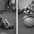
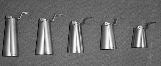
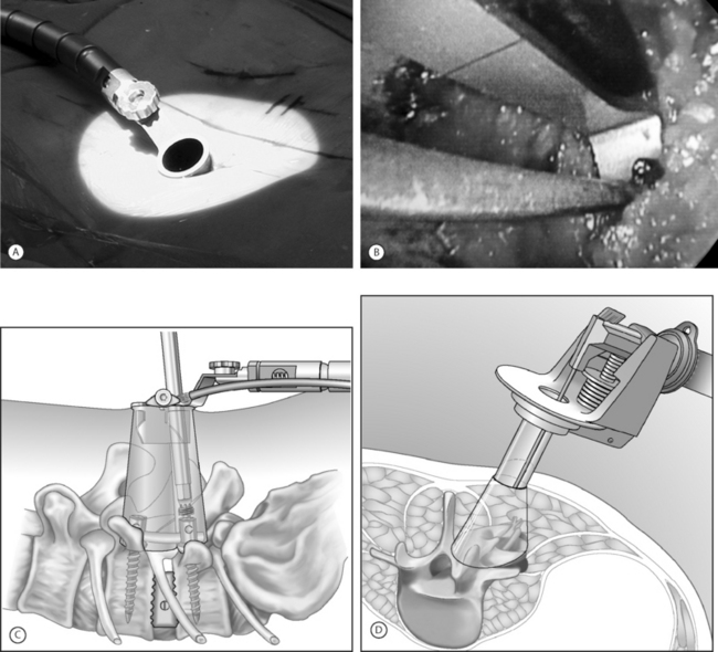
An expandable tubular retractor (X-Tube, Medtronic Sofamor Danek, Memphis, TN) (Fig. 132.1) can be used to accomplish a minimally invasive TLIF. The tube is inserted at a diameter of 26 mm and is expanded in situ to a final working diameter of 44 mm (which can span from pedicle to pedicle). Use of an endoscope or the operating microscope is possible through this tubular retractor (Fig. 132.2A). The basic surgical set is essentially the same as a standard laminectomy/fusion set. It is important to have a high-speed telescoping drill (Midas Rex, Ft. Worth, TX) available as an aid for removing bone. Instruments should be bayoneted so that visualization of the operative field is not occluded down the barrel of the tubular retractor. The tools for disc space preparation prior to graft placement consist of distractors (7–14 mm), rotating cutters, endplate scrapers, and chisel. Many options exist for interbody graft material and can include bone or cages (with autologous bone or BMP-2 [Medtronic Sofamor Danek, Memphis, TN]).
The operating room is arranged such that the operating table is in the center of the room, anesthesia at the head and fluoroscopy monitor at the foot. The C-arm base is placed on the side opposite of the TLIF as is the video monitor. Equipment tables are kept behind the surgeon on the operative side and a Mayo stand is situated over the feet to pass instruments in active use. The patient is positioned prone on a radiolucent Wilson frame over a Jackson table.
Localization and exposure
The anulus is cut and disc material is removed with pituitary rongeurs. A down-angled curette is helpful to ensure that subligamentous disc fragments and the contralateral disc are properly removed. The disc space is sequentially dilated until disc space height is similar to adjacent levels. The maximum insertable dilator translates into the width of the interbody graft used. Next, the rotating cutter is introduced parallel with the disc space and rotated to start preparing the vertebral body endplates. The endplates are scraped, and debris is removed with a pituitary rongeur. A disc space chisel can be used to better prepare the endplates. A graft of surgeon’s preference can now be placed (see Fig. 132.2B). Medial angulation of the tube will allow for midline graft placement. One should also pack autologous laminofacet bone removed during the decompression, anteriorly into the disc space prior to graft placement. The X-tube can also be repositioned laterally if a unilateral intertransverse fusion is desired.
Instrumentation with sextant
In essence, if percutaneous pedicle screw placement is not desired, surgical instruments and fixation can all be applied directly through the retractor port (see Fig. 132.2C). Examples of commercial access systems in addition to the METRx Minimal Access System (Medtronic Sofamor Danek; Memphis, TN), include the Access Port (Spinal Concepts; Austin, TX), the Nuvasive system (Nuvasive; San Diego, CA) and the ATAVI System (Endius; Plainville, MA). The central mechanism of each of these systems is fundamentally that of tubular dilation and a cylindrical working portal. Like the METRx Xpand system, the ATAVI Flexposure cannula (Endius) (see Fig. 132.2D) can expand its ultimate working diameter up to 40–60 mm for direct pedicle screw placement.
Laparoscopic anterior lumbar interbody fusion
Prior to the 1980s, laparoscopic procedures were mainly used in the field of gynecology and urology. The transition into general surgery began in the 1980s when the first laparoscopic appendectomy was performed in Germany. In 1987, the first human laparoscopic cholecystectomy was performed in France.3 The widespread acceptance of this minimally invasive approach can best be appreciated by noting the fact that within only 3 years after its introduction, more than 90% of all cholecystectomies were being performed laparoscopically. The significant advantages of transperitoneal laparoscopic surgical treatment include marked reductions in postoperative pain, early hospital discharges, and reduced incidences of postoperative ileus.
Anterior lumbar interbody fusion (ALIF) was initially described by Burns in 1933 for the treatment of spondylolisthesis.4 In 1995, Mathews et al.5 and Zucherman et al.6 described the technique in detail and published preliminary outcome data for laparoscopic anterior lumbar fusion. In 2000, Regan et al.7 published a prospective comparative study of open versus laparoscopic anterior lumbar fusion. They demonstrated that the laparoscopy group had a shorter hospital stay and reduced blood loss but had increased operative time. Operative time improved in the laparoscopy group as surgeons’ experience increased. Operative complications were comparable in both groups, with an occurrence of 4.2% in the open approach and 4.9% in the laparoscopic approach. Overall, the device-related reoperation rate was higher in the laparoscopy group (4.7% versus 2.3%). Conversion to open procedure in the laparoscopy group was 10%.
A more recent study did not favor the video-assisted techniques and laparoscopic approach. Escobar et al.8 published a comparative analysis focusing on the complications of three techniques (a ‘minilaparotomy’ open extraperitoneal approach through a small midline incision, a transperitoneal video-assisted insufflation technique, and a video-assisted gasless) for anterior lumbar interbody fusion in 135 patients. The study revealed the highest incidence of complications in video-assisted techniques and the laparoscopic approach. Complications are primarily related to surgical exposure of the anterior spine, which can include damage to important vascular structures, the sympathetic plexus, or the abdominal viscera.
Minimally invasive retroperitoneal lumbar fusion
The retroperitoneal approach to the lumbar spine was first described by Iwahara in 1963 and is now being increasingly used for treatment of spondylolisthesis,9–11 degenerative disc disease,11 internal disc derangement,4,12 instability,14 and for reoperations.14,15 Endoscopic approaches to the retroperitoneal space, called ‘retroperitoneoscopy,’ were initially described by urological surgeons in the 1990s. Gaur16 and McDougall et al.17 first used balloon dissection of the retroperitoneal space to enable laparoscopic visualization of the surrounding anatomy. This eventually gave rise to applications for treatment of lumbar disease. The balloon-assisted endoscopic retroperitoneal gasless(BERG) procedure is a minimally invasive retroperitoneal approach to the anterior lumbar spine. A gasless retroperitoneal approach has further advantages. This procedure is similar to an open spinal procedure, and conventional instruments may be implemented. Valved trocars are not required and the complications involved with carbon dioxide insufflation are avoided. Advances in interbody cage technology and artificial discs have generated a great deal of interest in anterior lumbar fusion. Minimal access techniques to the anterior lumbar spine will be important in optimizing clinical outcomes in addition to preserving posterior load-bearing elements.
Surgical technique
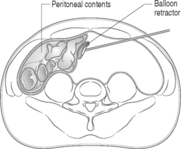
The second level of retraction is necessary to displace the peritoneal contents past the midline to provide access to the lumbar spine and vascular anatomy. A long retractor with an inflatable end is inserted through the newly created lateral working port in the initial left flank incision to push the peritoneal sac and intra-abdominal contents aside, creating the working space (Fig. 132.3). Once the retractor is in place, the technician stands with his or her abdomen against the retractor handle, leaving two hands free for endoscope operation.
THORACIC SPINE
Video-assisted thoracoscopic surgery
The history of thoracoscopy dates back to 1910 when Jacobaeus performed the first thoracoscopic and laparoscopic procedure.18 In 1990, the introduction of video imaging to standard endoscopy marked the modern era of thoracoscopic surgery. The technique of video-assisted thoracic surgery was first reported in 1993 by Mack et al.19 Video-assisted thoracic surgery has since played a major role in the treatment of thoracic disc herniations, treatment of spinal deformities requiring anterior release, and corpectomies for the treatment of vertebral body tumors.20–22 Several published reports demonstrated the efficacy of video-assisted thoracoscopic surgery for excision of thoracic disc herniations.23,24 Thoracoscopic spine surgery has also made treatment of hyperhidrosis possible in a minimally invasive way. Picetti et al.25 performed corrective surgeries with the thoracoscope in 50 patients who were diagnosed with thoracic scoliosis. Postoperative pain was less, as well as a shorter duration of postoperative analgesic use, in patients treated thorascopically as compared with patients treated with formal open procedures.
In the trauma series reported by Khoo et al,26 371 patients with fractures of the thoracic and thoracolumbar spine (T3–L3) were treated with a thoracoscopically assisted procedure. Seventy-three percent of the fractures were located at the thoracolumbar junction. In 49% of patients, mobilization of the diaphragm was performed thoracoscopically to expose the fracture site. The severe complication rate was low (1.3%), with one case each of aortic injury, splenic contusion, neurological deterioration, cerebrospinal fluid leak, and severe wound infection. Compared with a group of 30 patients treated with open thoracotomy, thoracoscopically treated patients required 42% less narcotics for pain treatment after the operation. A thoracoscopic approach can only access the anterior and anterolateral aspects of the vertebrae and spinal canal. It cannot adequately expose the posterior elements, the contralateral pedicle, or the transverse process. Thoracoscopic surgery, like endoscopic surgery, will require a steep learning curve but has the advantages of reducing post-thoracotomy pain syndromes and exposure-related morbidity.
Thoracoscopic decompression and fixation
As an alternative approach to thoracotomy or thoracoabdominal approach, thoracoscopic technique can be used to perform thoracic corpectomy to decompress the spinal canal, to reconstruct and fixate the segments affected by destructive disease and trauma. Within the thoracic cavity, thoracoscopic access to the thoracic vertebrae T4–12 can be easily accomplished. By thoracoscopically detaching the diaphragm, L1–3 can be reached so that it is possible to expose the entire thoracolumbar area for a minimally invasive endoscopic procedure (Fig. 132.4A). Thus, the thoracic spine as well as upper lumbar spine from T4 to L3 is accessible endoscopically using the thoracoscopic technique.
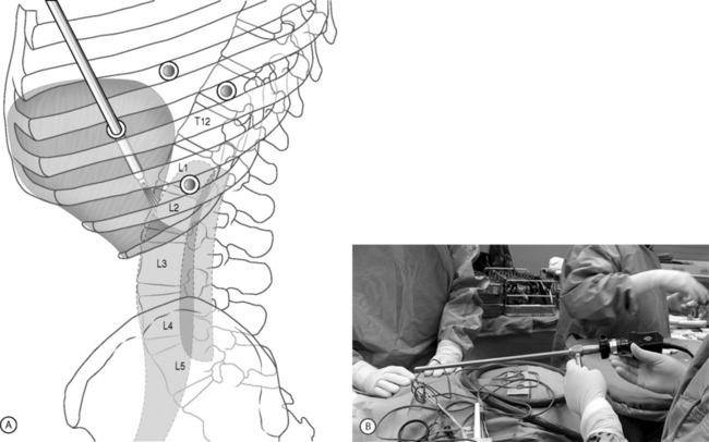
Surgical technique
Lung isolation with double lumen endotracheal intubation will be required for the thoracoscopic procedure. The patient is placed in a lateral position on a Jackson spinal table. A left-sided approach is preferred for the treatment of pathologies from T4 to T8. A right-sided approach is preferred for exposing the thoracolumbar junction (T9–L3). The upper arm is abducted and elevated so that it does not interfere with the placement and manipulation of the endoscope. The surgeon stands behind the patient. The surgical technique of thoracoscopic spine surgery is described in detail by various authors.26–28 Early on in the authors’ experience, they often reserved the thoracoscopic approaches for thoracic pathologies involving the T4 to T10 vertebrae. With increasing experience, the authors extended the indications to pathologies involving the thoracolumbar junction.
Placement of portals
The position of the portals in relation to one another and to the operating site on the spine influences the entire course of the operation. The operating portal is the first position to be marked exactly over the target area, and then, corresponding to this, the portal for the optic is drawn in over the spine, two or three intercostals spaces above the mark for the operating portal, for thoracolumbar access, or underneath it for access to the central or upper thoracic spine. Portal for the suction and irrigation instrument is about four fingerbreadths from the operating portal in a ventral and cranial direction. The portal for the diaphragm or lung retractor should be placed as far as possible ventrally to avoid instruments coming into conflict. Lung isolation should start prior to incision. Subsequently, the most cranial portal (optical channel) should be placed first. Through a 1.5 cm skin incision above the intercostal space, a muscle-splitting technique is used to bluntly open into the intercostal space. A 10 mm trocar is inserted into the thoracic cavity. A 30° endoscope is inserted at a flat angle in the direction of the second trocar (see Fig. 132.4B). Perforation of the thoracic wall to insert the remaining trocars is performed under direct intrathoracic visualization through the scope.
Corpectomy and decompression of the spinal canal
The extent of the planned partial vertebrectomy is defined with an osteotome.
Screw/plate/rod placement
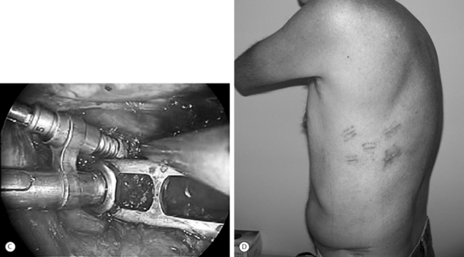
Thoracoscopic instrumentation can be performed via available systems (i.e. MACS-TL, Frontier) and invariably involves the use of cannulated top loading screws. Plates or rods can be used to interlink the screws for final stabilization (see Fig. 132.4C).
Closure
The gap in the diaphragm is closed with staples or adaptive sutures using endoscopic technique. The thoracic cavity is irrigated, blood clots are removed, and a chest tube is inserted with the end placed in the costodiaphragmatic recess. The portals are closed with sutures after removal of the trocars (see Fig. 132.4D).
CERVICAL SPINE
Minimally invasive cervical lateral mass screw fixation
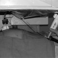
Although not without its limitations, posterior cervical instrumentation can also be accomplished via a minimally invasive approach. A ‘novel’ surgical technique of lateral mass screw fixation through a special tunnel retractor has recently been described (Fig. 132.5A). The procedure is performed in the prone position with the use of tubular retractors introduced at two or three levels below the area of pathology at an angle used for placement of the lateral mass screws. Dorsal elevation of the retractor system will provide room for placement of the rod. This technique can be applied to three contiguous cervical levels.
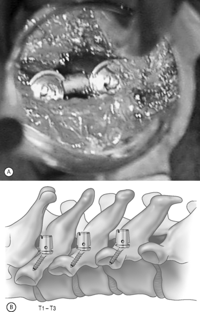
Newer lateral mass instrumentation systems utilize two rods and variable polyaxial screw islets at each level. These include the Cervi-Fix system (Synthes; Paoli, PA), StarLock System (Synthes; Paoli, PA), Summit System (Depuy Acromed), and Vertex (Medtronic Sofamor Danek; Minneapolis, MN). These systems vary by the angulation of their screws as well as in the degree of the constraint placed at the screw–rod interface. The polyaxial connectors of the screws are able to angle medially, laterally, and straight with varying degrees of rotational freedom in each direction. As such, segmental fixation is more easily achieved via a top-loading approach, thereby making minimally invasive posterior cervical fixation possible (see Fig. 132.5B). With the advent of some of the newer types of expandable access portals (e.g. FlexPosure (Endius; Plainville, MA) and Xpand (Medtronic Sofamor Danek; Memphis, TN), up to three lateral masses can be instrumented through a single exposure.
VERTEBROPLASTY/KYPHOPLASTY
Although not a fusion procedure in itself, vertebroplasty/kyphoplasty may obviate the need for a stabilization procedure via a minimally invasive way. Developed in France in the late 1980s, minimally invasive vertebroplasty involves the percutaneous injection of polymethyl methacrylate (PMMA) into a fractured vertebral body.30 Although this does not reexpand a collapsed vertebra, reinforcing and stabilizing the fracture seems to alleviate pain. The procedure was first used to treat aggressive vertebral hemangiomas30 and was later applied to other lesions that weaken the vertebral body, including osteolytic metastases31–34 and osteoporotic vertebral collapse. Although the European experience with vertebroplasty in the setting of spinal metastases and myeloma is more extensive, the indications for treatment in North America are currently heavily weighted toward osteoporotic bone disease. Percutaneous balloon kyphoplasty is a recent modification of the vertebroplasty technique and involves inflation of a balloon within a collapsed vertebral body to restore height and reduce kyphotic deformity followed by stabilization with PMMA. The risk of cement extravasation is theoretically reduced because the balloon creates a void within the vertebral body into which cement can be injected under relatively low pressure. In addition to PMMA and bone mineral cement, several alternative biological materials have been used in attempts to augment compromised vertebral bodies. The efficacy of osteoinductive growth factors (transforming growth factor-γ, bone morphogenetic protein-2, and bone morphogenetic protein-7) in enhancing arthrodesis is currently being studied among patients undergoing spinal instrumentation.
IMAGING GUIDANCE-ASSISTED SURGERY
Since its introduction, transpedicular screw fixation has been extensively utilized in various spinal disorders to promote fusion and stabilization. Screw misplacement can lead to undesirable neurovascular complications. Pedicle screw placement in patients with deformities carries an even greater risk of serious complications. Weinstein et al.35 reported pedicle cortex violation in close to 20% of these cases. To increase the accuracy of screw placement, various methods have been used to better target the pedicle with respect to the trajectory and depth of screw placement. Image-guided systems are widely used in intracranial surgery and have been adapted to assist with screw placement since the middle 1990s.36,37 The use of image-guided systems for pedicle screw placement has improved the accuracy of placement. The system relies on precise localization of the pedicles with computed tomography. Furthermore, by replacing direct visualization with radiographic visualization, it has enabled a reduction in surgical exposure, duration, and blood loss. Foley et al.1 described ‘virtual fluoroscopy’ and its successful use in various spinal procedures including pedicle screw insertion, interbody cage placement, odontoid screw insertion, and atlantoaxial transarticular screw fixation. Nolte et al.37 described the principles of computer-assisted pedicle screw fixation. An infrared camera (Optotrak; Northern Digital, Waterloo, Canada) tracked specific instruments (pedicle probe, awl, and space pointer) equipped with light-emitting diodes. The dynamic reference was fixed to the spinous process of the vertebra to be instrumented. Normal bony landmarks and their correlations with the images confirmed the calibration accuracy. Using that computerized system, Nolte et al.37 reported a pedicle screw misplacement rate of 4.3% under clinical conditions. In contrast, Choi et al.38 reported the use of computer-assisted fluoroscopic targeting for pedicle screw fixation. The authors compared the accuracy of pedicle screw placement with the fluoroscopy-guided system versus the image-guided system and observed no significant differences. Recent development of isocentric C-arm fluoroscopy, which generates CT images using an intraoperative fluoroscope, may offer another means of three-dimensional navigation using a two-dimensional intraoperative imaging source. With increasing familiarity, image-guided surgery will be a very useful adjunct to the further development of minimally invasive surgery.
1 Foley KT, Gupta SK. Percutaneous pedicle screw fixation of the lumbar spine: Preliminary clinical results. J Neurosurgery (Spine 1). 2002;97:7-12.
2 Foley KT, Holly LT, Schwender JD. Minimally invasive lumbar fusion. Spine. 2003;28:S26-S35.
3 Dubois F, Icard P, Berthelot G, et al. Coelioscopic cholecystectomy: Preliminary report of 36 cases. Ann Surg. 1990;211:60-62.
4 Burns BH. An operation for spondylolisthesis. Lancet. 1933;1:1233.
5 Mathews HH, Evans MT, Molligan HJ, et al. Laparoscopic discectomy with anterior lumbar interbody fusion: A preliminary review. Spine. 1995;20:1797-1802.
6 Zucherman JF, Zdeblick TA, Bailey SA, et al. Instrumented laparoscopic spinal fusion: Preliminary results. Spine. 1995;20:2029-2034.
7 Regan JJ, Yeun H, McAfee PC. Laparoscopic fusion of the lumbar spine: minimally invasive spine surger. a prospective multicenter study evaluating open and laparoscopic lumbar fusion. Spine. 2000;25:509-515.
8 Escobar E, Transfeldt E, Garvey T, et al. Video-assisted versus open anterior lumbar spine fusion surgery: A comparison of four techniques and complications in 135 patients. Spine. 2003;28:729-732.
9 Kim SS, Denis F, Lonstein JE, et al. Factors affecting fusion rate in spondylolisthesis. Spine. 1990;15:977-984.
10 Sacks S. Anterior interbody fusion of the lumbar spine: Indications and results in 200 cases. Clin Orthop. 1966;44:163-170.
11 Stauffer RW, Coventry MB. Anterior interbody lumbar spine fusion. J Bone Joint Surg [Am]. 1972;54A:756-768.
12 Calandruccio RA, Benton BF. Anterior lumbar fusion. Clin Orthop. 1964;35:63-68.
13 Harmon PH. Anterior extraperitoneal lumbar disk excision and vertebral fusion. Clin Orthop. 1960;18:169-198.
14 Sorensen KH. Anterior interbody lumbar spine fusion for incapacitating disc degeneration and spondylolisthesis. Acta Orthop Scand. 1978;49:269-277.
15 Takahashi K, Kitahara H, Yamagata M. Long-term results of anterior interbody fusion for treatment of degenerative spondylolisthesis. Spine. 1990;15:1211-1215.
16 Gaur DD. Laparoscopic operative retroperitoneoscopy: Use of a new device. J Urol. 1992;148:1137-1139.
17 McDougall EM, Clayman RV, Fadden PT. Retroperitoneoscopy: The Washington University Medical School experience. Urology. 1994;43:446-452.
18 Savitz MH, Chiu JC, Yeung AT. The practice of minimally invasive spinal technique. Richmond: AAMISMS Education Press, 2000.
19 Mack MJ, Regan JJ, Bobechko WP, et al. Application of thoracoscopy for diseases of the spine. Ann Thorac Surg. 1993;56:736-738.
20 McAfee PC, Regan JJ, Zdeblick T, et al. The incidence of complications in endoscopic anterior thoracolumbar spinal reconstructive surgery. A prospective multicenter study comprising the first 100 consecutive cases. Spine. 1995;20:1624-1632.
21 Nymberg SM, Crawford AH. Video-assisted thoracoscopic releases of scoliotic anterior spines. AORN J. 1996;63:561-576.
22 Regan JJ, Mack MJ, Picetti G. A technical report of video-assisted thoracoscopy (VATS) in thoracic spinal surgery: Preliminary description. Spine. 1995;20:831-837.
23 Horowitz MB, Moossy JJ, Julian T, et al. Thoracic discectomy using video assisted thoracoscopy. Spine. 1994;19:1082-1086.
24 Rosenthal D, Rosenthal R, De Simone A. Removal of a protruded thoracic disc using microsurgical endoscopy. Spine. 1994;19:1087-1091.
25 Picetti GD, Pang D, Bueff HU. Thoracoscopic techniques for the treatment of scoliosis: early results in procedure development. Neurosurgery. 2002;51:978-984.
26 Khoo LT, Beisse R, Potulski M. Thoracoscopic-assisted treatment of thoracic and lumbar fractures: a series of 371 consecutive cases. Neurosurgery. 2002;51(5 Suppl):104-117.
27 Beisse R, Potalski M, Temme C, et al. Endoscopically controlled division of the diaphragm. A minimally invasive approach to ventral management of thoracolumbar fractures of the spine. Unfallchirurg. 1998;101:619-627.
28 Beisse R, Potulski M, Buhren V. Endoscopic techniques for the management of spinal trauma. Eur J Trauma. 2001;27:275-291.
29 Wang MY, Prusmack CJ, Green BA, et al. Minimally invasive lateral mass screw in the treatment of cervical facet dislocations: technical note. Neurosurgery. 2003;52:444-447.
30 Deramond H, Depriester C, Galibert P, et al. Percutaneous vertebroplasty with polymethylmethacrylate: Technique, indications, and results. Radiol Clin North Am. 1998;36:533-546.
31 Barr JD, Barr MS, Lemley TJ, et al. Percutaneous vertebroplasty for pain relief and spinal stabilization. Spine. 2000;25:923-928.
32 Cotten A, Dewatre F, Cortet B, et al. Percutaneous vertebroplasty for osteolytic metastases and myeloma: Effects of the percentage of lesion filling and the leakage of methyl methacrylate at clinical follow-up. Radiology. 1996;200:525-530.
33 Martin JB, Jean B, Sugiu K, et al. Vertebroplasty: Clinical experience and follow-up results. Bone. 1999;25(Suppl 2):11S-15S.
34 Weill A, Chiras J, Simon JM, et al. Spinal metastases: Indications for and results of percutaneous injection of acrylic surgical cement. Radiology. 1996;199:241-247.
35 Weinstein JN, Spratt KF, Spengler D, et al. Spinal pedicle fixation: Reliability and validity of roentgenogram-based assessment and surgical factors on successful screw placement. Spine. 1988;13:1012-1018.
36 Glossop ND, Hu RW, Randle JA. Computer-aided pedicle screw placement using frameless stereotaxis. Spine. 1996;21:2026-2034.
37 Nolte LP, Zamorano LJ, Jiang Z, et al. Image-guided insertion of transpedicular screws: A laboratory set-up. Spine. 1995;20:497-500.
38 Choi WW, Green BA, Levi AD. Computer-assisted fluoroscopic targeting system for pedicle screw insertion. Neurosurgery. 2000;47:872-878.