Chapter 12 Films, cassettes, intensifying screens and processing
 Radiographic film is composed of a film base with an active emulsion layer adhered using a subbing layer, with a protective super-coat.

 The latent image is converted into a permanent visible image through the use of developer and fixer.

FILMS
The production of an X-ray image depends upon the existence of materials that are unstable and, when exposed to light or electromagnetic radiation, change their nature. Halogens such as bromine or iodine are combined with silver to produce silver bromide or silver idobromide.
FILM MANUFACTURE AND SENSITIVITY
FILM CONSTRUCTION
Duplitised emulsion
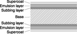
The majority of screen-type film is ‘duplitised’. This type of film has two sensitive emulsion layers – one on each side of base (Fig. 12.1). It is used for most general applications. However duplitised emulsions are also used for intra-oral dental film, although in this instance the film is exposed directly to X-radiation alone.
Film base
It is essential that the base should be:
Supercoat/anti-abrasive layer
Single-sided emulsion
Single emulsion
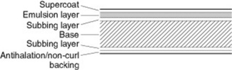
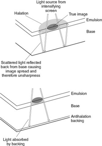
This is similar in construction to duplitised film; however, the second emulsion layer is replaced with an anti-curl/halo backing (Fig. 12.2). Curl may occur during processing as the emulsion layer absorbs processing chemicals and water and expands to a certain degree. To avoid this a layer of gelatin of identical thickness to the emulsion layer is applied to the non-emulsion aspect of the film. During processing this will expand to the same degree as the emulsion, ensuring that the dry film will lie flat. In single-sided emulsions light can be reflected at the base–air interface, back towards the sensitive emulsion layer, thus creating a halo effect (Fig. 12.3).
To minimise the halo effect a coloured dye is incorporated within the gelatin of the anti-curl backing. This acts as a colour filter and absorbs light of specific wavelengths, increasing the resolution of the image. The dye colour utilised is always the opposite colour to the exposing light source; for example yellow dye to absorb blue light. The anti-halation dye is bleached out in the fixer during the processing cycle. Processors that process large numbers of single-sided films require a higher fixer replenishment rate than those that primarily process duplitised films, as the removal of anti-halation dye utilises more fixer energy.
Advantages of using duplitised emulsions
Image resolution and use of films
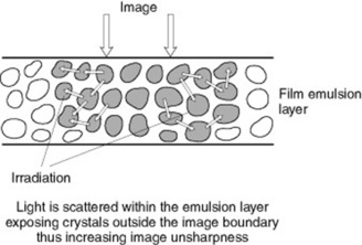
Irradiation
This is the sideways scattering of light within the emulsion layer as a consequence of light striking the silver halide crystals (Fig. 12.4). This is a cause of image unsharpness, as the scattered light does not contribute to the primary image.
Halation
Halation occurs when an image is formed by light and some of this incident energy passes through the emulsion to the base. On reaching the base–air interface this light either passes out of the film or is reflected back towards the emulsion layer where it creates unsharpness by interacting with silver halide crystals.
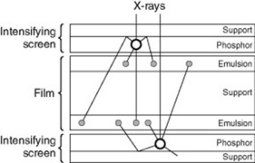
Crossover
Crossover creates an increase in image unsharpness because light that is not completely absorbed in the emulsion layer nearest to source of light passes through the film base and subsequently interacts with silver halide crystals in the opposite emulsion layer, creating a wider and thus less sharp image (Fig. 12.5).
CASSETTES
In radiographic terms a cassette normally houses and provides a physically safe and light-tight environment for both the film and the intensifying screens in which the processes associated with fluorescence and the formation of the latent image can occur (Fig. 12.6). Cassettes are available in various sizes and with detailed differences between specific manufactures.
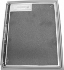
CONSTRUCTION
INTENSIFYING SCREENS
CONSTRUCTION OF INTENSIFYING SCREENS
The detailed construction of an intensifying screen can vary widely; it is, however, closely related to its planned use in clinical practice and comprises a number of discrete layers (Fig. 12.7).

Phosphor layer
This layer consists of the phosphor crystals; suspended in a transparent binding material such as polyurethane. The nature of the phosphor crystals will vary depending upon the planned spectral emission of the intensifying screen. The speed of the intensifying screen will depend upon both the type of phosphor crystal used and the density to which they are packed. Within high definition intensifying screens the use of coloured pigment or carbon granules in the binder material tends to absorb laterally scattered light within the phosphor layer. This minimises photographic unsharpness but requires an increase in radiation exposure to the patient.
PHOSPHOR TYPES
Modern rare earth phosphors, such as gadolinium oxysulphide, lanthanum oxybromide, yttrium oxysulphide and others, generally have both a higher detection and conversion efficiency than the older mostly blue/violet-light emitting materials such as calcium tungstate or barium lead sulphate. Rare earth phosphors are normally used in conjunction with a small amount of an activator, the combination of which determines both the spectral emission, colour of the emitted light, and its intensity of luminescence. For example a combination of gadolinium oxysulphide with terbium as an activator emits green light whilst lanthanum oxybromide with thulium emits blue light. Rare earth phosphors tend to emit the majority of light produced at discrete wavelengths and are referred to as ‘line emitters’, whilst older type materials, such as calcium tungstate, emit light continuously between specific wavelengths and hence are ‘broad spectrum emitters’ (Fig. 12.8).

MATCHING FILM SPECTRAL SENSITIVITY AND SPECTRAL EMISSION
It is essential that the film’s sensitivity is matched directly to the spectral emission of the intensifying screens in order to achieve maximum filmblackening from a given radiation exposure to the patient (Fig. 12.9). When an orthochromatic-type film is used with intensifying screens emitting green light it can be seen that the majority of the light emitted by the intensifying screens lies within the spectral sensitivity curve of the film. This ensures optimal performance of the system. However, if a monochromatic-type film is used with the same intensifying screens, the majority of the light emitted by the screens lies outside the film’s spectral sensitivity curve. Therefore, most of the emitted light will have minimal impact on the silver halide crystals within the film’s emulsion.

TYPES OF INTENSIFYING SCREEN
Enhanced image resolution may be achieved by the use of absorptive material within the substratum and inclusion of coloured dyes within the binding material of the phosphor layer. Except in special circumstances, intensifying screens are paired facilitating the use of duplitised film emulsions (see p. 136). In such circumstances the back intensifying screen will receive slightly fewer X-ray photons than the front screen due to absorption within both the front screen and the film itself. Thus the two images may be of a slightly different density. Manufacturers may either choose to ignore this and produce a pair of screens of identical speed. Alternatively they may opt to increase the speed of the back screen by the use of a reflective layer or greater coating weight or use a pigment to reduce the speed of the front screen.
INTENSIFYING SCREENS AND IMAGE RESOLUTION
The use of screens plays a significant role in reducing the radiation dose received by patients. The following features of their construction make a significant contribution to the final image resolution:
PROCESSING
DEVELOPMENT
The developer solution has various constituents including:
FIXATION
Major functions of fixation include:
Constituents of fixer
AUTOMATIC PROCESSORS
The basic components within an automatic processor are very similar despite the differences that occur between manufacturers products in relation to design and film capacity (Fig. 12.10).

MAIN CONTENTS OF THE PROCESSOR
The processor is essentially a light-tight box containing:


FIXER SECTION
The fixer section contains drainage, recirculatory and replenisher systems that are similar in function to those within the developer section (Fig. 12.13). The temperature control will be dependent on the design of the processor and may utilise heat exchange from the surrounding warm developer and wash tanks. In the case of cold-water wash units the temperature control is achieved by using an immersion heater thermostat device, with insulation provided in the dividing wall between the fixer and wash sections. The precise control of fixer temperature is not as critical as it is for developer solution.

WASH SECTION
DRYING SECTION
There is danger to the film emulsion if the air used for drying is too hot. A microswitch is present to prevent film damage. There are a number of different systems available to dry films (Fig. 12.14).

TRANSPORT SYSTEM
The film transport system comprises a series of rollers arranged in racks, driven by an electric motor at a constant speed (Fig. 12.15).

FILM FEED SYSTEM
This system activates all the main processor functions and, in instances when manual loading of the processor occurs, gives an audible signal that it is safe to feed another film into the processor (Fig. 12.16). Different systems are utilised to achieve this, including:

REPLENISHMENT SYSTEM
As a film passes through the beam is broken. This calculates the film size and the required amount of replenishment. As films are processed then the nature of both the developer and fixer solution is subject to change. This occurs because the by-products of the process can alter the nature of the solution. Some solution is carried over on the film, reducing the amount present in the tanks and causing some contamination. Developer solution can become less active as it oxidises in the air and so constant replacementis essential. In order to maintain both solution activity and level, replenishment of solutions is essential (Fig. 12.17). Replenishment may occur whilst each film is fed into the processor when the microswitch is activated or is related to the area of film processed as calculated by infrared detector. The latter is the most accurate method.

AUTOMIXERS (CHEMICAL MIXERS)
Mixers (Fig. 12.18) may differ in construction and mode of operation but all systems provide:

CARE AND MAINTENANCE OF THE AUTOMATIC PROCESSOR AND CHEMICAL MIXER
AUTOMATIC PROCESSOR CARE
These are guidelines; the specific care provided by manufacturers should be followed.
Daily
Weekly
In addition manufactures recommend the periodic drainage and cleaning of fixer and developer tanks.
PROCESSOR QUALITY CONTROL
Routine assessment should also be made of:
A change to the nature of processing solutions occurs as a result of use; solution replenishment is designed to maintain the maximum function of both developer and fixer. Checks on processing chemistry include:
SENSITOMETRIC TESTS
Manual
This requires the use of a densitometer, and as the density of specific parts of the image must be recorded manually it is a somewhat lengthy and time-consuming procedure. Results are used to plot graphs that investigate trends by recording the fog levels, density and contrast (Fig. 12.19).

Ball J, Price T. Chesneys’ radiographic imaging, 6th edn. Oxford: Blackwell Science, 1998.
This text provides a clear description of all aspects of processing and films..
Gunn C. Radiographic imaging: a practical approach, 3rd edn. Edinburgh: Churchill Livingstone, 2002.
Environmental Protection Act 1990. London: HMSO.
The Control of Substances Hazardous to Health Regulations 2002 (SI 2002/2677). London: HMSO.