[level-membership-for-cardiovascular-category]
Chapter 4 Evaluation of the Aortic Valve
Introduction
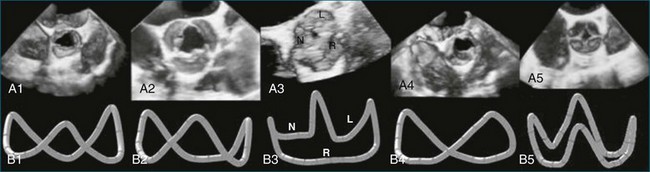
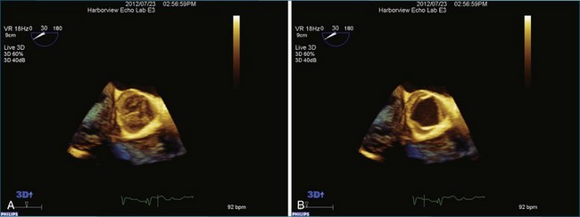
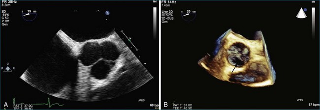
The aortic valve is the third largest valve in the body, behind the tricuspid and mitral valves, and has a typical valve area of 3 to 4 cm2. Despite its smaller size, it is arguably the most important because it lies between the high-resistance aorta and the high pressure–generating left ventricle. Like the pulmonary valve, the aortic valve is semilunar in nature; the major difference between the two semilunar valves is that the left and right coronary arteries arise from the aortic valve and from the left and right coronary sinuses of Valsalva, respectively. However, the aortic valve is also a more resilient valve than the pulmonic valve, as has been shown when the pulmonic valve has been switched into the aortic position in the Ross procedure.1 The anatomy of the semilunar valves is unique in that a discrete, well-defined annulus, as in the mitral and tricuspid valves, is not present. That is, there is no well-formed fibrous band of tissue encircling the aorta, even though clinicians, especially surgeons, speak of this. Rather, there is a curvilinear attachment of the aortic valve cusps to the aortic wall. Real-time three-dimensional transesophageal echocardiography (RT3DTEE) has been used to reconstruct the aortic valve annulus, which has been shown to have significant variation depending on whether it is tricuspid, bicuspid, calcified, or quadricuspid (Figure 4-1).2 In fact, the aortic annulus has the appearance of a crown and is well visualized in Figure 4-1. Furthermore, the valve cusps attach to tissue in both the aortic wall as well as the left ventricular arterial junction in a curvilinear fashion. The aortic valve cusps have a main core of tissue with endocardial lining present on each side. The individual leaflets meet at a central line of coaptation, the center of which is a thickened nodule called the nodule of Arantius (Figure 4-2). This nodule has important anatomic significance for RT3DE imaging because the extent of the nodule thickening often cannot be completely appreciated by two-dimensional echocardiography (2DE), and complete visualization is important in pathology of the valve leading to aortic regurgitation.2–4 The body of the aortic valve leaflets is well seen by RT3DE, as opposed to 2DE (Figure 4-3).
Aortic Valve Pathology and Real-Time Three-Dimensional Echocardiography
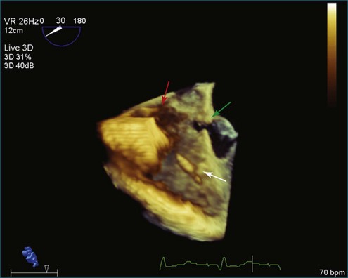
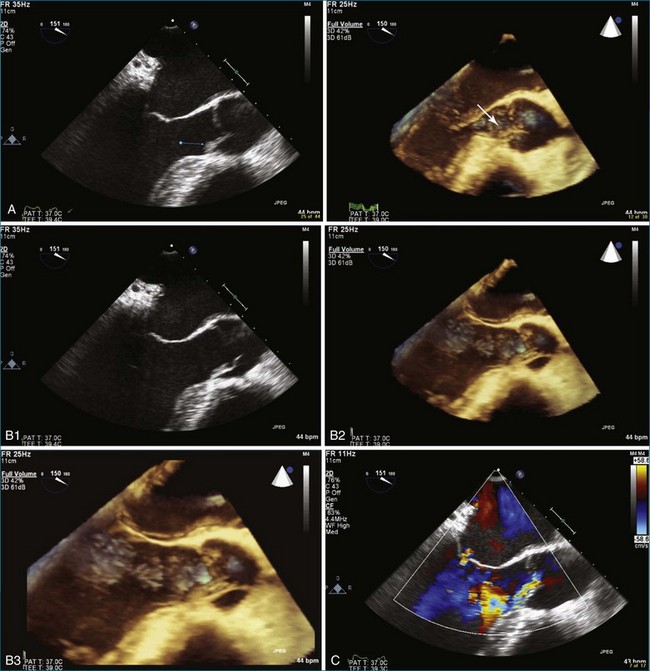
The evaluation of the aortic valve, including the sinuses of Valsalva and the aortic root, by both 2DE and 3DE has become even more important in modern-day cardiology because of the advent of the percutaneously delivered aortic valve and the ability to close defects in the aortic root and sinuses of Valsalva by using percutaneously placed vascular plugs.5 The characteristic Gerbode defect, defined as right coronary sinus of Valsalva rupture into the right atrium, is just one example in which RT3DTEE can particularly perform well in terms of visualization of the many (right atrium, right coronary sinus of Valsalva, tricuspid valve, interatrial and interventricular septae) structures that are in proximity to each other (Figure 4-4; Video 4-1). The anatomic relationships of these structures are not trivial, and RT3DTEE can sort them out nicely in many, if not all, instances.1,2 My own experience with closing the Gerbode defect with vascular plugs using RT3DTEE guidance has been extremely favorable.
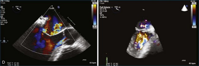
The most common clinically significant aortic valve lesion is calcific aortic stenosis; this problem is becoming more and more common as the population ages. Significant hemodynamic effects develop with aortic stenosis when the valve area reaches roughly one fourth its normal value, depending on patient size. In young and middle-aged patients with aortic stenosis, the cause is frequently bicuspid aortic valve.6 RT3DE of the aortic valve can produce quite satisfactory images, particularly of bicuspid aortic valves, although visualization of the valve leaflets typically is more challenging than that of the mitral valve because the leaflets are very thin in the former (Figure 4-5; Videos 4-2 to 4-8). The advantage of RT3DE over traditional 2DE is the ability to visualize the body of the valve leaflets as opposed to only the borders of the leaflets at the coaptation point and as they come together to form the commissures at the circumference of the aortic valve. This particular strength of RT3DE is shown in Figure 4-6 with direct comparison with 2DE imaging in the same patient. A step-by-step approach to acquisition of the RT3DTEE dataset, starting with the 2DTEE views and then moving to the 3D zoom mode, is described (Videos 4-9 to 4-14). Both RT3D transthoracic echocardiography (TTE) and RT3DTEE have been extensively used for evaluation of the disease of the cusp body. Because the most common cause of aortic stenosis is degenerative or calcific aortic stenosis, RT3DE is particularly useful because that type of aortic stenosis preferentially involves the body of the aortic cusps. The same is true for evaluation of the precursor of calcific aortic stenosis: aortic sclerosis (Figure 4-7; Videos 4-15 to 4-17). For aortic regurgitation, the second most common clinically significant aortic valve lesion, RT3DE can provide data about the degree of regurgitation, particularly by evaluating the 3D vena contracta of the regurgitation, especially with regard to the etiology of the aortic regurgitation.
One of the first reports specific for RT3DE imaging of the aortic valve, performed by Blot-Souleti,12 looked at the accuracy of aortic stenosis quantitation using RT3DTTE. Previously, there had been multiple reports of the general use of RT3DTTE to visualize many structures, including the aortic valve.7 Blot-Souleti’s study was, however, a comprehensive evaluation of the first experience with RT3DTTE. Later, several case reports of imaging bicuspid aortic valves by RT3DTTE appeared. Imaging of a quadricuspid aortic valve by RT3DTTE was described by Aggarwal, Burri, and Chen, and that of the unicuspid aortic valve by Matsumoto.8–11 In the first report, the right upper sinus of Valsalva ruptured into the right atrium, which was well visualized by RT3DTTE as well as color RT3DTTE. Figure 4-8 shows a quadricuspid valve by 2DE and RT3DTEE (Videos 4-18 and 4-19).
As previously mentioned, the accuracy of imaging the aortic valve area in aortic stenosis by RT3DTTE has been compared with the 2D continuity equation and TEE planimetry, with a correlation of 0.82 and 0.94, respectively.12 Furthermore, aortic stenosis imaging accuracy by RT3DTTE was compared with catheterization and planimetry by 2DTEE, and only very small absolute differences (between 0.01 and 0.15 cm) were noted.13 Aortic annular motion is a significant pitfall in measuring the aortic valve area by 2DTEE planimetry. This seems to be at least partially overcome by using the volumetric data obtained by RT3DTEE.14
Bicuspid Aortic Valve Pathology and Real-Time Three-Dimensional Echocardiography
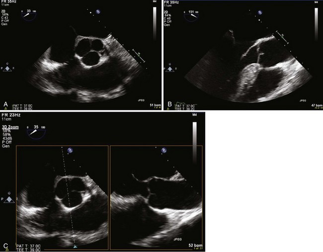
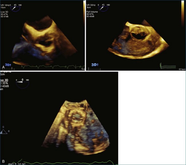
Bicuspid aortic valves typically can be diagnosed with 2DTTE imaging, although in some patients transthoracic imaging is inadequate and 2DTEE is necessary. However, RT3DE imaging can visualize the presence or absence of a raphe between the fused cusps as well as the relationship of the raphe to the other cusps and the coronary arteries. This characterization is useful from a prognostic standpoint, since bicuspid aortic valves with an anterior or posterior orientation with the coronary arteries arising from the anterior cusp have more complications and less longevity than the right or left orientation. Furthermore, bicuspid valves with a raphe have a worse prognosis than those without.15–17 Also, the presence or absence of a raphe as well as presence of a cleft have been reported to affect surgical repair in patients who have valve preservation surgery.18 Hence, imaging of the bicuspid valve morphology by RT3DE becomes important because (1) bicuspid aortic valve is the most common congenital heart defect, present in 2% of the population; and (2) RT3DE is the imaging test of choice to evaluate for the presence and extent of a raphe. Examples of RT3DTEE views of bicuspid aortic valves are shown in Figure 4-9 (Videos 4-20 and 4-21.)
Endocarditis of the Aortic Valve and Real-Time Three-Dimensional Echocardiography
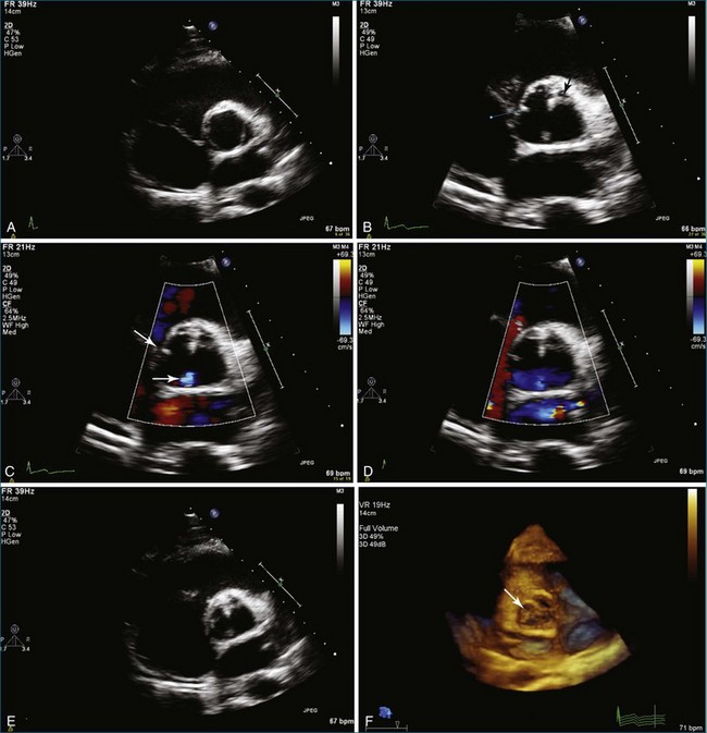
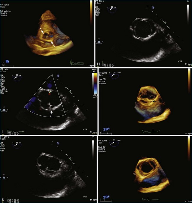
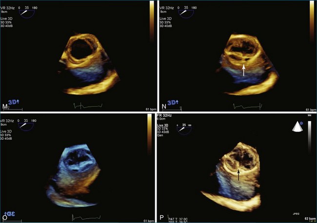
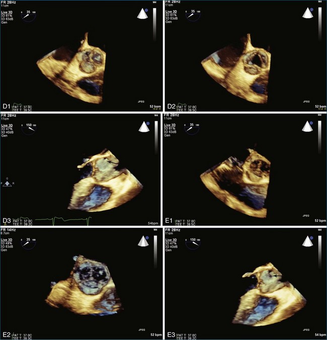
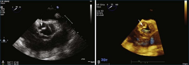
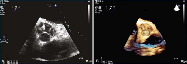
Endocarditis is a significant cause of aortic regurgitation in adult patients with trileaflet aortic valves. In addition, when an abscess cavity develops in endocarditis, the aortic valve is involved in 83% of the cases. Evaluation of endocarditis by RT3DE has been shown to improve the accuracy of vegetation size and morphology and also aid in the diagnosis of abscess cavity associated with the endocarditis process. For aortic valve endocarditis specifically, both RT3DTTE and RT3DTEE have been used extensively to determine aortic valve cusp integrity and to diagnose an abscess cavity associated with the aortic valve. Figure 4-10 shows several examples of aortic valve endocarditis visualized by RT3DTEE (Videos 4-22 to 4-26).
Interventional Procedures and the Aortic Valve by Real-Time Three-Dimensional Echocardiography
Interventional procedures involving the aortic valve, including transcatheter aortic valve implantation, closure of paraaortic prosthetic aortic valvular leak, closure of sinus of Valsalva ruptured aneurysm, and closure of aortic root pseudoaneurysms have all been described with RT3DTTE or RT3DTEE guidance.19 Closure of paraaortic prosthetic aortic valvular leak, in fact, is quite difficult to perform without RT3DTEE. Figure 4-11 shows imaging of a transcatheter-placed aortic valve by RT3DTEE. Evaluation of the aortic annulus size has been shown to be more accurate by 3DTEE than by 2DTEE when compared with magnetic resonance imaging.
Prosthetic Aortic Valves
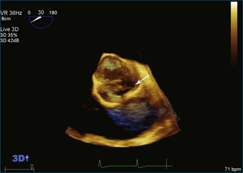
Although prosthetic valve imaging by RT3DE is covered in Chapter 8, it is important to mention RT3DE imaging specifically for the aortic position. The good news is that on the basis of my experience, there is less shadowing from the prosthetic valves with RT3DE than with traditional 2DE. This, however, is not easily explained, since RT3DE still uses ultrasound and shadowing artifact from prosthetic material remains a significant limitation. So, this is a small triumph. However, the unfortunate news is that compared with the mitral valve, the aortic valve remains much more difficult to image by any echocardiography modality. And, as in the 2D realm, although TEE helps dramatically with mitral imaging, TEE helps only to a certain extent for imaging the aortic valve. Finally, in the case of patients with mechanical prosthetic valves in both the mitral and aortic positions, aortic valve imaging remains a substantial challenge. Figure 4-12 shows an example of imaging of a prosthetic aortic valve by RT3DTEE. Further aortic valve images of interest are shown in Figures 4-13 to 4-18; Videos 4-27 to 4-34).
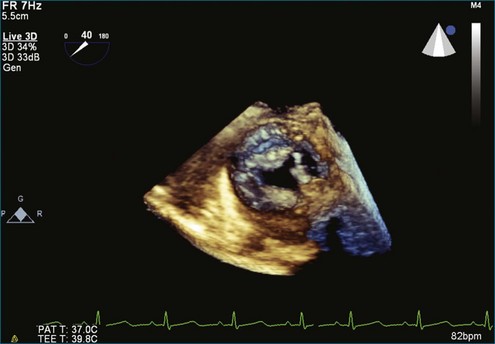
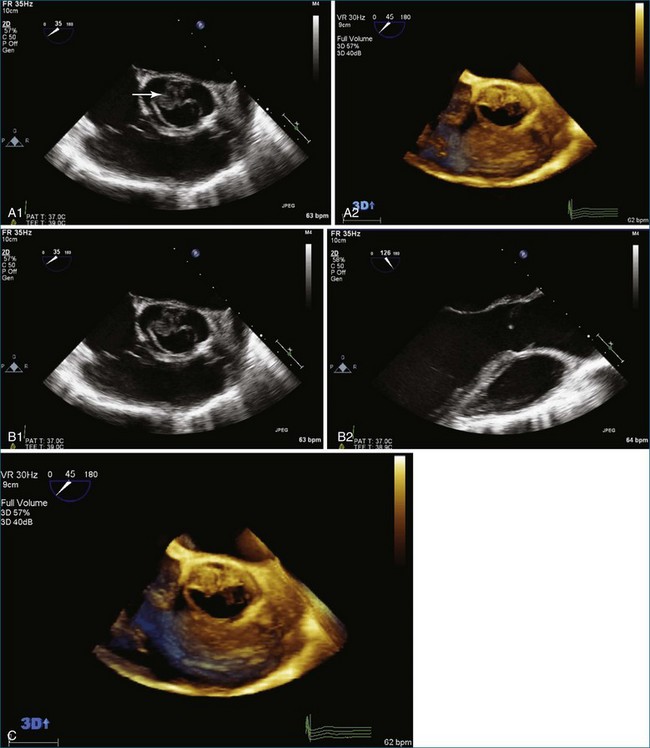
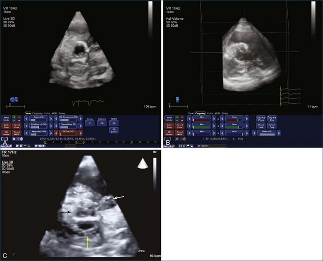
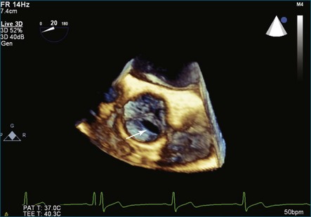
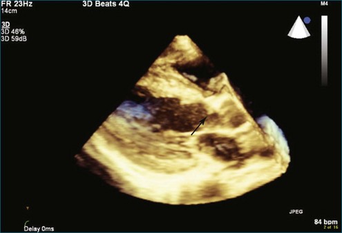
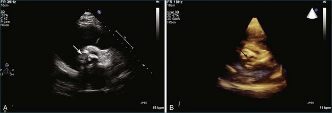
Figure 4-16 Subaortic membrane (arrow) by real-time three-dimensional transthoracic echocardiography (see Video 4-31).
1 Hanke T, Charitos EI, Stierle U, et al. The Ross operation—a feasible and safe option in the setting of a bicuspid aortic valve? Eur J Cardiothorac Surg. 2010;38:333–339.
2 Ren B, Tang H, Kang Y. Visualisation of the aortic annulus using the real-time three-dimensional transesophageal echocardiography. Heart. 2011;97:862–863.
3 Janosi RA, Kahlert P, Plicht B, et al. Measurement of the aortic annulus size by real-time three-dimensional transesophageal echocardiography. Minim Invasive Ther Allied Technol. 2011;20:85–94.
4 Otani K, Takeuchi M, Kaku K, et al. Assessment of the aortic root using real-time 3D transesophageal echocardiography. Circ J. 2010;74:2649–2657.
5 Dvir D, Kornowski R. Percutaneous aortic valve implantation using novel imaging guidance. Catheter Cardiovasc Interv. 2010;76:450–454.
6 Subramanian R, Olson LJ, Edwards WD. Surgical pathology of pure aortic stenosis: A study of 374 cases. Mayo Clin Proc. 1984;59:683–690.
7 Pepi M, Tamborini G, Pontone G, et al. Initial experience with a new on-line transthoracic three-dimensional technique: Assessment of feasibility and of diagnostic potential. Ital Heart J. 2003;4:544–550.
8 Aggarwal SK, Lingan A, Reddy KK, et al. Quadricuspid aortic valve with ruptured sinus of valsalva aneurysm to the right atrium. Echocardiography. 2009;26:977–979.
9 Burri MV, Nanda NC, Singh A, Panwar SR. Live/real time three-dimensional transthoracic echocardiographic identification of quadricuspid aortic valve. Echocardiography. 2007;24:653–655.
10 Chen M, McRee D. An incidentally discovered quadricuspid aortic valve: Echocardiographic and clinical characteristics. J Diagn Med Sonogr. 2009;25:93–96.
11 Matsumoto K, Tanaka H, Hiraishi M, et al. A case of unicommissural unicuspid aortic valve stenosis diagnosed by real time three-dimensional transesophageal echocardiography. Echocardiography. 2011;28:E172–E173.
12 Blot-Souletie N, Hebrard A, Acar P, et al. Comparison of accuracy of aortic valve area assessment in aortic stenosis by real time three-dimensional echocardiography in biplane mode versus two-dimensional transthoracic and transesophageal echocardiography. Echocardiography. 2007;24:1065–1072.
13 Goland S, Trento A, Iida K, et al. Assessment of aortic stenosis by three-dimensional echocardiography: An accurate and novel approach. Heart. 2007;93:801–807.
14 Nakai H, Takeuchi M, Yoshitani H, et al. Pitfalls of anatomical aortic valve area measurements using two-dimensional transoesophageal echocardiography and the potential of three-dimensional transoesophageal echocardiography. Eur J Echocardiogr. 2010;11:369–376.
15 Schaefer BM, Lewin MB, Stout KK, et al. The bicuspid aortic valve: An integrated phenotypic classification of leaflet morphology and aortic root shape. Heart. 2008;94:1634–1638.
16 Guntheroth W. Risk of aortic dissection in patients with bicuspid aortic valves. Am J Cardiol. 2011;107:958.
17 Iqtidar AF, O’Rourke DJ, Silverman DI, et al. Predictors of rapid aortic dilatation in adults with a bicuspid aortic valve. J Heart Valve Dis. 2011;20:292–298.
18 Mangini A, Lemma M, Contino M, et al. Bicuspid aortic valve: Differences in the phenotypic continuum affect the repair technique. Eur J Cardiothorac Surg. 2010;37:1015–1020.
19 Hoffmayer KS, Zellner C, Kwan DM, et al. Closure of a para-valvular aortic leak: With the use of 2 AMPLATZER devices and real-time 2- and 3-dimensional transesophageal echocardiography. Tex Heart Inst J. 2011;38:81–84.
[/level-membership-for-cardiovascular-category][not-level-membership-for-cardiovascular-category]
Chapter 4 Evaluation of the Aortic Valve
Introduction
The aortic valve is the third largest valve in the body, behind the tricuspid and mitral valves, and has a typical valve area of 3 to 4 cm2. Despite its smaller size, it is arguably the most important because it lies between the high-resistance aorta and the high pressure–generating left ventricle. Like the pulmonary valve, the aortic valve is semilunar in nature; the major difference between the two semilunar valves is that the left and right coronary arteries arise from the aortic valve and from the left and right coronary sinuses of Valsalva, respectively. However, the aortic valve is also a more resilient valve than the pulmonic valve, as has been shown when the pulmonic valve has been switched into the aortic position in the Ross procedure.1 The anatomy of the semilunar valves is unique in that a discrete, well-defined annulus, as in the mitral and tricuspid valves, is not present. That is, there is no well-formed fibrous band of tissue encircling the aorta, even though clinicians, especially surgeons, speak of this. Rather, there is a curvilinear attachment of the aortic valve cusps to the aortic wall. Real-time three-dimensional transesophageal echocardiography (RT3DTEE) has been used to reconstruct the aortic valve annulus, which has been shown to have significant variation depending on whether it is tricuspid, bicuspid, calcified, or quadricuspid (Figure 4-1).2 In fact, the aortic annulus has the appearance of a crown and is well visualized in Figure 4-1. Furthermore, the valve cusps attach to tissue in both the aortic wall as well as the left ventricular arterial junction in a curvilinear fashion. The aortic valve cusps have a main core of tissue with endocardial lining present on each side. The individual leaflets meet at a central line of coaptation, the center of which is a thickened nodule called the nodule of Arantius (Figure 4-2). This nodule has important anatomic significance for RT3DE imaging because the extent of the nodule thickening often cannot be completely appreciated by two-dimensional echocardiography (2DE), and complete visualization is important in pathology of the valve leading to aortic regurgitation.2–4 The body of the aortic valve leaflets is well seen by RT3DE, as opposed to 2DE (Figure 4-3).
Aortic Valve Pathology and Real-Time Three-Dimensional Echocardiography
The evaluation of the aortic valve, including the sinuses of Valsalva and the aortic root, by both 2DE and 3DE has become even more important in modern-day cardiology because of the advent of the percutaneously delivered aortic valve and the ability to close defects in the aortic root and sinuses of Valsalva by using percutaneously placed vascular plugs.5 The characteristic Gerbode defect, defined as right coronary sinus of Valsalva rupture into the right atrium, is just one example in which RT3DTEE can particularly perform well in terms of visualization of the many (right atrium, right coronary sinus of Valsalva, tricuspid valve, interatrial and interventricular septae) structures that are in proximity to each other (Figure 4-4; Video 4-1). The anatomic relationships of these structures are not trivial, and RT3DTEE can sort them out nicely in many, if not all, instances.1,2 My own experience with closing the Gerbode defect with vascular plugs using RT3DTEE guidance has been extremely favorable.
The most common clinically significant aortic valve lesion is calcific aortic stenosis; this problem is becoming more and more common as the population ages. Significant hemodynamic effects develop with aortic stenosis when the valve area reaches roughly one fourth its normal value, depending on patient size. In young and middle-aged patients with aortic stenosis, the cause is frequently bicuspid aortic valve.6 RT3DE of the aortic valve can produce quite satisfactory images, particularly of bicuspid aortic valves, although visualization of the valve leaflets typically is more challenging than that of the mitral valve because the leaflets are very thin in the former (Figure 4-5; Videos 4-2 to 4-8). The advantage of RT3DE over traditional 2DE is the ability to visualize the body of the valve leaflets as opposed to only the borders of the leaflets at the coaptation point and as they come together to form the commissures at the circumference of the aortic valve. This particular strength of RT3DE is shown in Figure 4-6 with direct comparison with 2DE imaging in the same patient. A step-by-step approach to acquisition of the RT3DTEE dataset, starting with the 2DTEE views and then moving to the 3D zoom mode, is described (Videos 4-9 to 4-14). Both RT3D transthoracic echocardiography (TTE) and RT3DTEE have been extensively used for evaluation of the disease of the cusp body. Because the most common cause of aortic stenosis is degenerative or calcific aortic stenosis, RT3DE is particularly useful because that type of aortic stenosis preferentially involves the body of the aortic cusps. The same is true for evaluation of the precursor of calcific aortic stenosis: aortic sclerosis (Figure 4-7; Videos 4-15 to 4-17). For aortic regurgitation, the second most common clinically significant aortic valve lesion, RT3DE can provide data about the degree of regurgitation, particularly by evaluating the 3D vena contracta of the regurgitation, especially with regard to the etiology of the aortic regurgitation.
