[level-membership-for-cardiovascular-category]
4 Engineering and Construction of Pacemaker and ICD Leads
Tremendous advances have occurred in implanted cardiac device therapy, from the evolution of pacemakers to the modern era of high-voltage defibrillation and resynchronization devices. Advances in the components, integrated circuitry, size, and software of the implantable pulse generator are readily apparent, but the revolutionary progress in the design and manufacture of device leads is often not appreciated. In any device system, the lead is the critical interface linking the pulse generator and the myocardium; it allows for communication of electrical signals from the heart to the pulse generator through the sensing circuitry, and in the reverse direction, it allows for bradycardia pacing or tachyarrhythmia therapy. Although leadless pacing1 and defibrillation2 device systems are being actively developed, leads clearly will remain an integral component of device therapy for the foreseeable future.
 Pacing Leads
Historical Milestones in Development
Permanently implantable pacing leads evolved from the temporary pacing wires that were first used to provide bradycardia support.3 The initial permanent transvenous leads were unipolar and consisted of a basic conductor, an insulator, and a connector pin. The electrodes were large and polished with high-polarization properties, low electrode-tissue impedance, and excessive current drain. No lumen was present in these leads to allow for stylet insertion, so lead implantation was a long, difficult task. Also, no fixation mechanism was present, so lead displacement rates were high. The development of bipolar pacing leads minimized far-field oversensing,4 requiring a major reconsideration of lead body design and structure, because two longitudinal conductors needed to coexist inside the lead, separated only by a thin layer of insulation. This and subsequent increases in complexity required advances in materials science so as not to compromise reliability.
The development of passive-fixation tines was a huge step forward and dramatically reduced the rate of reoperation for lead dislodgement compared with existing flange-tipped pacing leads.5–7 Active-fixation helices were introduced subsequently and further improved the stability of implanted leads. Modern electrodes were developed with small geometric surface area but large effective area as a result of porous surfaces, and these optimized the trade-off between high current density and low polarization. Chronic threshold rises and late exit block were still major problems in cardiac pacing at that stage, however, and remained so until the revolutionary incorporation of an elutable dexamethasone reservoir into a porous-tip electrode, essentially eliminating this complication.8 Although this likely resulted from the glucocorticoid and not the redesigned porous titanium-tip electrode, this remained unproved until a pioneering randomized double-blind trial compared two otherwise identical leads and electrodes, with and without steroid elution.9 This unequivocally demonstrated the benefit was the result of the dexamethasone. Subsequent advances have included the universal standardization of connector pins (and consequently device headers), improving lead longevity through the use of better component materials, and improving sensing through the use of narrower bipoles.
Lead Structure And Polarity
The basic functions of any cardiac device lead—pacing and sensing—require conductors for current flow between the pulse generator and myocardium and insulators to prevent short-circuiting of this current. These elements may be configured in two ways. First, a pace/sense circuit may be composed of a lead containing one conductor that connects to a negatively charged tip electrode, the cathode, from which electrons flow through the myocardium and thoracic cavity back to the active, positively charged pulse generator (IPG), the anode (Fig. 4-1, A). Such a lead, with only one conductor and electrode, is called a unipolar lead because only one electrode is in contact with the heart (although it is part of a bipolar circuit). It has been established that pacing thresholds are lower at most pulse widths when the intracardiac pacing electrode is configured as the cathode rather than as the anode10 (see Chapter 1). Although once the only option, unipolar leads have largely been replaced by bipolar leads. The alternative system consists of a lead body containing two conductors (separated and surrounded by insulation) that connect to a cathode-tip electrode and an anode ring electrode located several millimeters more proximally (Fig. 4-1, B). The IPG is not an active electrode in a bipolar circuit, and such leads are said to have bipolar configuration.
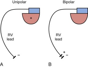
Unipolar systems have a large interelectrode distance from the tip of the intracardiac lead to the IPG, and this large field of view makes them vulnerable to the oversensing of myocardial signals (T waves or electrograms from another chamber, known as “crosstalk”) and far-field nonmyocardial signals such as pacing artifacts (another form of crosstalk), skeletal myopotentials, and nonphysiologic electrical “noise” in up to 38% of patients.11 Electrical signal oversensing can have significant consequences on pacing behavior, including ventricular output inhibition and inappropriate mode switching caused by far-field ventricular oversensing on the atrial channel.12,13 Because of the additional consequence of inappropriate shock delivery if oversensing were to occur in an ICD, it is particularly important for ICD leads to have bipolar sensing circuitry. Since the IPG itself serves as one of the electrodes in a unipolar system, skeletal muscle capture and pectoral muscle stimulation may result in the setting of a higher programmed pacing output. Bipolar leads have been shown to have similar but slightly higher, acute and chronic stimulation thresholds to unipolar leads.4 Bipolar leads also carry an element of redundancy in that they can be used in either the bipolar or the unipolar configuration, as in isolated failure of the proximal, anodal conductor, with no demonstrated difference in performance between the two pacing configurations.14 In addition, the much lower amplitude of the bipolar pacing artifact greatly reduces the likelihood of crosstalk and oversensing. The great advantage of bipolar leads is related to their superior sensing properties. These factors have led to the near-universal adoption of the bipolar lead as the configuration of choice in cardiac device systems.15 The only potential disadvantage of bipolar leads is that reliability is lower than with the less complicated unipolar lead,16 although some studies have not supported this contention.15,17
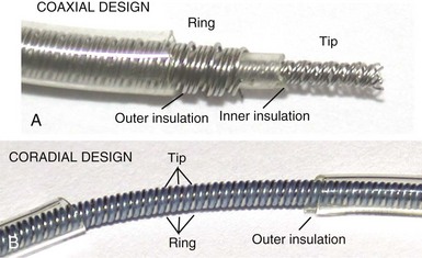
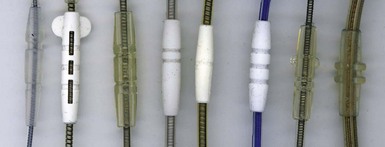
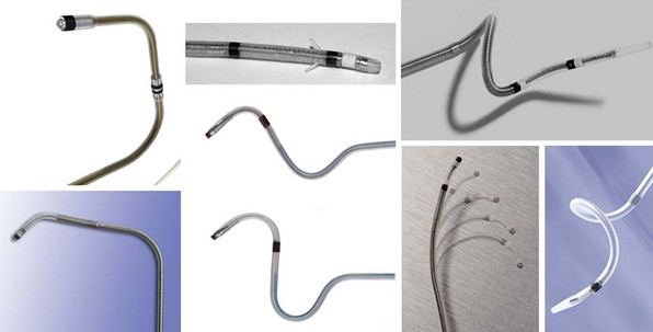
However, insulation failure usually has negligible effects on unipolar lead performance, a clear reliability advantage. In terms of the structure of the lead body, the simple, single-conductor design of unipolar leads had to be modified to accommodate the greater number of components and increased complexity of the bipolar lead body. There are two main bipolar lead designs, coaxial and coradial (Fig 4-2). Coaxial leads have an inner conductor that extends down the length of the lead to the tip electrode, the cathode, arranged in a coil configuration with a central lumen to allow for passage of a stylet at implantation. This coil is covered by a cylindrical length of inner insulation, which in turn is wrapped by another coil conductor that also runs down the lead to the ring electrode, the anode. A second, outer layer of insulation and lead covering protect the ring conductor from the outside environment, thereby completing the design. Although this coaxial model has been the industry standard for pacing leads for many years, the resulting bulk and stiffness of this four-layer design are significant compared with the simpler unipolar leads. Coradial bipolar leads addressed some of these concerns with new conductor and insulator technology that was subsequently used in ICD lead design. In coradial leads, a single coil extends down the length of the lead (again with a central lumen to allow for stylet insertion) and consists of two parallel, alternating conductor strands, one of which connects to the cathode and the other to the anode. Each conductor strand is individually coated with a bonded layer of ethylene tetrafluoroethylene (ETFE) fluoropolymer insulation (originally by DuPont, Wilmington, Del), which serves to insulate each strand from the other, despite being intertwined. The single, two-component coil is surrounded by a single, outer insulation covering.18 These leads have comparable bulk (~5F diameter) and flexibility to unipolar leads, often with tines or a fixed, nonretractable helix to minimize size; electrical parameters and reliability have not been demonstrably inferior to coaxial leads.18–21
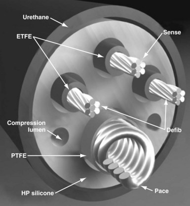
Defibrillator leads have even greater complexity, with two, three, or four conductors that connect to the pacing/sensing electrodes as well as to the high-voltage shocking coil(s), depending on the specific type of lead. Because of the prohibitive bulk that would result from a coaxial design with more than two conductors, ICD leads generally have a different type of structure, known as a multilumen design. This type of ICD lead consists of a long cylinder of insulating material, with separate internal channels running down its length (Fig. 4-3). Each conductor runs down an individual channel, usually with its own additional covering tube of insulation. The configuration and number of channels differ, depending on the number of conductors, the specific manufacturer, and whether air-filled channels are also incorporated into the design to improve lead handling and protect the conductors from flexion-related damage in the dynamic intracardiac and intravascular environment.
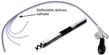
One other lead body structure worth mentioning are small (4.1F diameter), isodiametric, lumenless pacing leads (Model 3830 SelectSecure; Fig. 4-4). The lack of a central lumen and the use of a conductor cable (rather than coil) allows for increased insulation redundancy, high tensile strength, and reduced bulk. It also means that the active-fixation helix is nonextendable because there is no central coil conductor to transmit torque from the connector pin to extend or retract the helix. Fixation of such leads to the myocardium is achieved by turning the entire lead body. To enable implantation without a stylet, the lead is deployed through an 8.5F steerable catheter delivery system (SelectSite C304). Short-term results from this lead have been reasonable, with no signs of increased lead displacement or fracture risk.22,23 The small external diameter of this lead has been considered to be of some benefit in pediatric patients24 and patients with congenital heart disease,25 but the suggestion of a resulting improvement in chronic venous patency from the smaller size is yet to be substantiated in long-term follow-up. In addition, selective site pacing, in both the atria and the ventricles, is facilitated by the deflectable sheath, although steerable and preformed stylets can also be used with conventional leads to achieve this. No published experience with extraction of chronically placed lumenless leads exists, and the lack of a lumen to accommodate a lead-locking device may be a significant disadvantage of this design.
Conductors
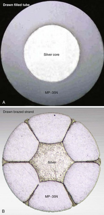
Both the coaxial and the coradial bipolar pacing lead body designs have been in widespread use and proved to be relatively fracture resistant over time. This durability is at least partially related to the materials and design of the conductor elements used in pacing leads. One study found conductor fracture over a 17-year follow-up in 19 of 561 right ventricular pacing leads (3.4%) and then generally at points of high stress, such as at the lead anchoring sleeve and the costoclavicular ligament (subclavian crush).26 The basic material used for most conductors over the last 3 to 4 decades has been MP-35N (SPS Technologies, Cleveland), an alloy of nickel, cobalt, chromium, and molybdenum. The main advantage of MP-35N is its high strength and resistance to corrosion.27 Its main disadvantage is its high electrical resistance, but this has been overcome with the development of composite-wire conductors that incorporate low-resistance metals such as silver and stainless steel with high-strength materials such as titanium, platinum, and platinum-iridium alloy.
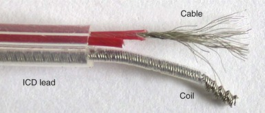
In pacing leads, these materials are generally incorporated into a drawn filled tube (DFT) composite-wire conductor strand consisting of a thick, strong body of MP-35N or titanium that has been filled with a central core of softer, low-resistance metal such as silver, often encased in a further outer shell of platinum alloy (Fig. 4-5, A). The DFT conductor strands are then formed into multifilar (i.e., multiple strands or filaments) coils with a central lumen in coaxial leads, as described earlier, or further coated in a layer of ETFE fluoropolymer before being arranged in bifilar coradial coils,28 again with a central lumen. The alternative way of forming a composite-wire conductor is the drawn brazed strand (DBS) method, generally consisting of six strands of a high-resistance material (e.g., MP-35N) that are tightly molded over a central strand of silver, such that the inner, low-resistance metal is forced between and around the strong outer strands (Fig. 4-5, B). This results in a low-resistance, durable composite conductor wire that can once again be formed into a multifilar coil for use in pacing leads.29 However, it is also used to form strong, multifilar, braided cables that are employed as the conductors for the high-voltage circuitry of ICD leads. DBS cables are discussed later.
Insulation
Pacing lead insulation is a critical and vulnerable component that is often the cause of lead failure.30,31 One of the problems with the major materials used for lead insulation (polyurethane, silicone rubber, fluoropolymers) is that they were not originally designed specifically for this purpose, and each has disadvantages when used as part of a biologic pacing system. They were incorporated by early lead engineers into their designs for lack of any purpose-built alternatives, and it is only recently that any viable, tailored alternatives have been developed.
Poly(ether)urethane is a synthetic, segmented polymer with very high tensile strength and resistance to mechanical abrasion. From a physical perspective, this means that a thinner layer of insulation can be used to cover the lead conductors, thereby reducing the overall lead diameter. Also, polyurethane has excellent lubricity and handling characteristics, with a low frictional coefficient, which can facilitate implantation of two or three lead systems by decreasing the physical interactions between the leads. However, polyurethane leads are stiffer and not fully biostable, being subject to in vivo polymer degradation that can cause insulation and late lead failure.32 The two main types of polyurethane are Pellethane 80A and Pellethane 55D (Upjohn, CPR Division, Torrance, Calif), with 80A particularly prone to biodegradation.
Two mechanisms of in vivo, biologically mediated degradation of polyurethane predominate: environmental stress cracking (ESC) and metal ion oxidation (MIO)33 (Fig. 4-6). When polyurethane is subjected to repeated mechanical stresses in the presence of surface-active agents provided by macrophages and α2-macroglobulin, parallel polymer molecules are disordered and interchain bonds weakened. This is the mechanism of ESC,34 manifesting as a deep surface cracking visible with electron microscopy, particularly at the anchoring sleeve and venous entry portions of the lead. By comparison, no mechanical stress is required for MIO to develop because this is a chemical reaction that occurs particularly at the conductor-insulator interface.35 Biologic oxidants, such as peroxide from surrounding inflammatory cells,36 can result in the release of metal cations from the conductor, especially cobalt and nickel ions. These cations cause oxidation of the soft zones in the polymer, starting at the α-carbon of the ether bond and resulting in chain break. The harder Pellethane 55D is much less susceptible to both ESC and MIO than 80A but is significantly stiffer. Nevertheless, the long-term performance of Pellethane 55D has been much better than Pellethane 80A, a material notoriously prone to failure.
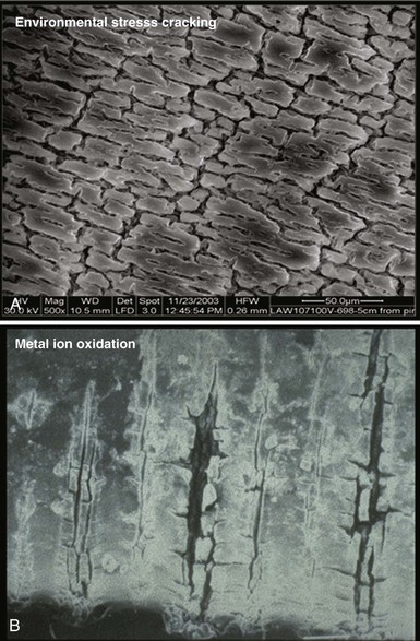
Figure 4-6 Mechanisms of polyurethane insulation failure on electron microscopy.
(Courtesy St Jude Medical, Sylmar, Calif.)
Silicone rubber (polysiloxane) has none of the disadvantages of polyurethane. It is completely inert and biostable over extended periods and thus not vulnerable to MIO or ESC. Silicone is more flexible, which may decrease the risk of damage to cardiac structures, including lead perforation. It is also more thermally resistant to the effects of electrocautery, which can be a significant advantage during pulse generator replacement or system revision.37 Initially, a softer peroxide-catalyzed silicone rubber, MDX4-4515-50A, was used for pacing leads, but new versions with higher tensile strength and abrasion resistance have been developed. These include high-performance (HP) silicone, extra-tear-resistant (ETR) silicone, and Novus (Med-4719, Nusil Technologies, Carpinteria, Calif), produced by hybridizing HP and MDX4 silicone. Unfortunately, no variety of silicone rubber has the positive characteristics of polyurethane, including surface lubriciousness and ease of handling. Although these friction-related problems of silicone can be addressed by an outer layering of polyurethane, the main problem with silicone relates to its lower tensile strength and susceptibility to abrasion and tears (Fig. 4-7, A). This means that silicone insulation is more prone to damage during implantation and subsequent interactions in the device pocket, and that a thicker insulation layer must be used to maintain lead reliability, thereby increasing lead bulk. Also, as with glass, silicone is a fluid material and thus prone to a gradual flowing process away from pressure points, known as “cold flow,” which can lead to thinned, denuded, and abraded troughs or depressions adjacent to areas of thickened rubber polymer32 (Fig. 4-7, B).
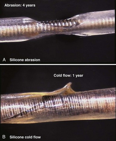
Figure 4-7 Mechanisms of silicone rubber insulation failure.
(Courtesy St Jude Medical, Sylmar, Calif.)
The fluoropolymers polytetrafluoroethylene (PTFE) and ETFE (DuPont) have some of the advantages of both silicone and polyurethane, with good abrasion resistance and biostability.38 Unfortunately, their great stiffness excludes them from functioning as the primary insulating material in any lead, but they can be used, as outlined earlier, as a thin coat on conductor strands, particularly in coradial leads. This inner insulating layer can prevent electrical communication between conductor strands and can also protect them from interacting with an adjacent outer layer of polyurethane, thereby reducing MIO.
Recently, the development of a specific insulation material for cardiac leads has suggested that the deficiencies of the standard insulators in pacing leads may finally be addressed. The material is a copolymer hybrid composed of 48% silicone, 40% polyurethane hard segment, and 12% polyhexamethylene oxide soft segment; it is called Elast-Eon (Aortech Biomaterials, Clayton, Victoria, Australia). This blending of insulating materials results in the product having the strength, lubricity and abrasion resistance of polyurethane, but the flexibility and biostability of silicone.39 Early bench and clinical testing have been promising to date, with little evidence of cold flow, ESC, or MIO phenomena, the main weaknesses of silicone and polyurethane. The material has been used in the St. Jude Medical Optim family of pacing (Models 1888T and 2088T) and ICD leads (Durata), but no long-term data on its chronic performance are yet available.
Electrodes
The materials used for lead electrodes have evolved over the past 40 years and have included titanium, anodized platinum, platinum-iridium alloys, Elgiloy (an alloy of cobalt, iron, chromium, molybdenum, nickel, and manganese), and vitreous carbon. All these display relative inertness in vivo, which minimizes inflammatory reactions and corrosion over the long term. Minor corrosion is seen, however, with Elgiloy and platinum alloys when in situ for extended periods, although this is of uncertain clinical significance.40 While attempting to control for other differences, several human and animal studies have compared these materials, but the results are conflicting.41–44 In general, applications have been found for these materials in electrode composition, with most having reasonable in vivo performance and longevity, although vitreous carbon cathodes have particular strength, inertness, and long-term electrical reliability.45
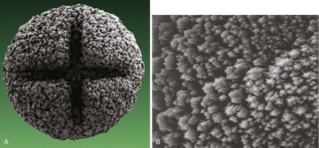
More important than the precise material composition of electrodes seems to be their geometry, particularly the surface area. A large cathodal surface area in contact with the endocardium results in a low current density at the electrode-tissue interface and consequently a higher capture threshold. As tip electrodes were reduced in surface area, apart from better thresholds, higher tissue-electrode impedances were also seen, and this increased pulse generator longevity.46,47 Against this beneficial effect of a smaller electrode is the adverse effect on tissue polarization seen with a smaller electrode surface area. Polarization refers to the electrical afterpotential generated at the electrode-tissue interface by ionic movement induced by the pacing stimulus. At pacing pulse delivery, a layer of positively charged cations is attracted to and surrounds the negatively charged cathode (and a larger layer of negatively charged anions surrounds the cation layer), which opposes current flow from the pacing electrode. This polarization potential is recorded as an afterpotential following the stimulus artifact. To maximize the advantages of small-radius electrodes, yet minimize the disadvantage of the polarization effect more prominent with smaller electrode surface area, current electrodes are small in size but have a complex, porous microscopic surface (Fig. 4-8). Regardless of the method of achieving a complex, highly textured surface, such as coating the electrode with microspheres or a woven mesh of microscopic metallic fibers, the resulting large surface area has proved beneficial with regard to pacing and sensing performance.
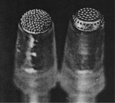
Figure 4-8 Sintered porous electrode (left) and laser porous electrode (right).
(From Hirshorn MS, Holley LK, Skalsky M, et al: Characteristics of advanced porous and textured surface pacemaker electrodes. PACE 6:525-536, 1983.)
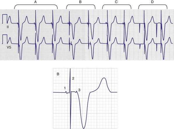
Titanium nitride–coated or iridium-coated cathodes with fractal surface structure achieve the goal of enhanced surface area with a negligible polarization signal48 (Fig. 4-9). Such electrodes have permitted the development of beat-by-beat automatic capture threshold and pacing output management systems that measure the evoked myocardial response following every pacing stimulus. By verifying myocardial capture for each paced beat, with the immediate delivery of a backup higher-output pulse if capture is lost (Fig. 4-10), the pacemaker can maintain a pacing output only marginally above the capture threshold, thereby prolonging pulse generator battery life.49 Another type of automatic threshold algorithm does not verify beat-to-beat capture, but performs an automatic threshold test daily and adjusts the pacing output accordingly (with larger safety margin above capture threshold). These types of automatic capture-detection algorithms can be unreliable in the setting of a significant polarization afterpotential, because a large polarization signal cannot be distinguished from the local myocardial evoked response.50
Electrodes implanted in myocardium elicit a strong foreign body granulomatous reaction that results in the formation of a local fibrous capsule at the lead tip, which can have a profound effect on electrical performance. Smooth-surfaced electrodes elicit the formation of a thick, electrically insulating capsule of fibrous and granulation tissue that may impede electrode fixation to the endocardium.51 Complex, porous electrodes, in contrast, are manufactured to have extremely small (20-50 µ in diameter) surface pores that allow for endocardial attachment by way of tissue ingrowth into these regions, which yields a mechanical advantage in addition to the electrical benefits mentioned earlier. A fibrous reaction also occurs with highly textured electrodes, but a lesser insulating effect is observed because the electrically active myocardium is closer to the electrode,51 resulting in improved electrical parameters over time.52
To curtail further the fibrous reaction elicited by the electrode and to decrease the incidence and magnitude of chronic threshold rises, a pharmacologic anti-inflammatory strategy was pursued with glucocorticoid-eluting porous electrodes (Fig. 4-11). These leads showed excellent long-term capture and sensing parameters, with a dramatic reduction in late exit block (i.e., loss of myocardial capture).8 In an elegant and seminal double-blind randomized trial, Mond et al.9 conclusively proved the beneficial effect of steroid elution by comparing two otherwise identical porous titanium electrodes, only one of which incorporated dexamethasone in its tip. There was no difference in capture threshold seen at implant. Although there was an expected late rise in threshold in the standard leads starting at 2 weeks, this was completely abolished in the steroid-eluting lead, both during the trial period and in long-term follow-up.53 Animal studies confirmed that the biologic basis of this electrophysiologic effect was through the glucocorticoid-induced attenuation of the inflammatory reaction, with thinner, less cellular fibrous capsules.54
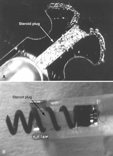
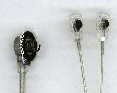
Figure 4-11 Dexamethasone-eluting reservoirs in passive-fixation (A) and active-fixation (B) leads.
(Courtesy St Jude Medical, Sylmar, Calif.)
In bipolar leads, another factor affecting electrical performance, particularly far-field sensing, is the interelectrode distance between the tip cathode and the ring anode. Narrow-spaced bipolar electrodes in atrial leads have been shown to reduce far-field ventricular electrogram sensing without compromising atrial sensing.55 In a randomized trial that compared an atrial lead with a 1.1-mm tip-to-ring spacing (Model 1699T Optisense, St. Jude Medical) with a standard 10-mm spacing, the close-spaced bipole showed minimal far-field ventricular sensing at a sensitivity of 0.3 mV, compared to 30% 1-year incidence in the standard-bipole group.56 This translated into a large reduction in inappropriate mode switch events, from 23% in the control group to 4% in the narrow-bipole group.
Fixation Mechanisms
Initial pacemaker leads had no fixation mechanisms, so lead dislodgement rates were high. The first solutions to this problem were wedge-shaped flanges and fins, but these had limitations. The development of scalloped tines was the first robust solution to the problem of lead displacement,5 and comparisons with earlier methods of passive fixation were favorable.57 Tines are usually constructed from the same material as the covering insulation of the lead, typically silicone rubber, and protrude backward from the base of the tip electrode. Their orientation is designed to allow advancement of the lead for initial implantation but to prevent retraction and dislodgement by engaging the myocardial trabeculae of the right atrial appendage and right ventricular apex (Fig. 4-12, A).
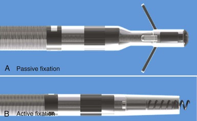
Although passive-fixation tined leads perform well, with low rates of dislodgement, they are less reliable for pacing at nontraditional sites, and the development of active-fixation leads with a helix at the tip improved the options for pacing site selection (Fig. 4-12, B). These leads generally have an extendable-retractable screw made of platinum-iridium or similar alloy that is usually electrically active as part of the cathode. This terminal helix is deployed (i.e., extended out of lead) with clockwise rotation of the connector pin, which transmits torque via the central coil conductor to the helix mechanism at the other end of the lead. A small number of leads use a stylet-driven extension-retraction mechanism. Some smaller-diameter leads have a fixed helix that requires rotation of the entire lead body around the stylet for deployment into the myocardium. Steroid elution from a reservoir at the base of the helix helps to dampen the inflammatory reaction produced by traumatic engagement of the myocardium by the screw. Active- and passive-fixation leads perform similarly overall,58 with some differences related to their construction. Active leads tend to be easier to extract, whereas passive leads tend to have lower chronic thresholds with higher impedances that prolong pulse generator longevity. The clinician must always consider the potential for perforation59 and trauma to surrounding structures60 when using active-fixation leads.61
Lead Anchoring Sleeves
Securing the lead body to the fascia or muscle at the floor of the device pocket at implantation is an important step to prevent lead dislodgement. The sutures used must be fastened firmly but, given the relative fragility of lead insulation as previously outlined, must not be allowed to compromise the lead structure or integrity (Fig. 4-13). Although the anchoring sleeve provides a mechanism to achieve this balance, there has been little development in this area. After being tied down tightly, sleeves made of MDX silicone were found to produce much lower lead deformation than ETR silicone,62 but no long-term in vivo data are available. Suture sleeves that grasp the lead by snapping into place (rather than relying on circumferential deformation of sleeve by encircling suture) have been proposed but are not in current use.
Connector Terminal Pins
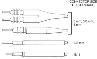
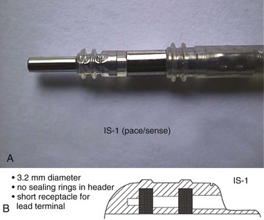
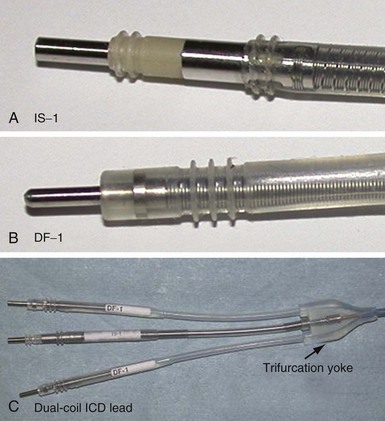
The connector terminal pin forms the interface of the lead with the header of the pulse generator and has gone through significant evolution. With successive generations of pulse generator and lead technology, various standards for connector terminal pins for pacing leads have been used,63,64 as well as two different pin-fixation mechanisms within the device header, the side lock, and the now-universal set screw. Reliability has been high with both pin-header fixation interfaces, although the more forgiving tolerance of the set-screw platform has led to its widespread adoption.65 This design requires a self-sealing grommet to cover the head of the set screw and prevent corrosion of the pin or header connections because pocket fluid enters the header. Sealing fins are required around the lead body or within the header channel to prevent fluid leaking into the header at that site, regardless of the fixation mechanism. Different patterns of connector pins include the 5- and 6-mm-long pins, the 3.2-mm low-profile pin, the VS-1 pin, and the current standard IS-1 connector pin (Fig. 4-14). Compatibility between terminal pin type and header channel type is still of major concern when changing pulse generators in patients with older leads. Modern pulse generator headers conform to IS-1 specifications (Fig. 4-15) and are backwards-compatible with VS-1 pins. Occasionally, for example, adapters may be required to downsize a long pin connector to an IS-1 header.
 Resynchronization Leads
The symptomatic and prognostic benefits of cardiac resynchronization therapy (CRT) in congestive heart failure patients with electrical dys-synchrony (asynchrony), usually in the form of native left bundle branch block (LBBB) or right ventricular pacing, have been repeatedly demonstrated in those already receiving maximal medical therapy.66,67 Leads used for providing CRT are exposed to different implant conditions than conventional pacing leads and thus have different design parameters. The benefits of CRT were first demonstrated with the placement of left ventricular (LV) epicardial leads. CRT leads can be implanted directly on the epicardium by an open or video-assisted thoracotomy. These leads are, or have similar characteristics to, standard epicardial pacing leads (Fig. 4-16). They are generally sutured or screwed in place on the lateral LV wall. Increasingly, patients who undergo cardiac surgery for coronary disease or valve dysfunction, but who also have heart failure, LV dysfunction, or a chronic need for pacing because of heart block, are having LV epicardial leads implanted at surgery, with the terminal pin end tunneled up to the left infraclavicular fossa for future connection to a CRT device.
Lead Placement and Fixation Mechanisms
For accessing the stimulation site, CRT lead systems come with a range of outer guide introducers to facilitate coronary sinus cannulation and provide support during lead placement. Although the initial transvenous CRT leads were stylet driven, over-the-wire leads were rapidly introduced because of difficulty negotiating venous tortuosities and acute takeoff angles. The development of an over-the-wire system was a major advance,68 and such leads are routinely required to select and place leads in the best possible target venous branches, usually over the posterolateral left ventricle. These leads allow for front or back loading of a 0.014-inch angioplasty wire into the stylet lumen. With or without the assistance of inner guiding catheters, the wire may be used to subselect target venous branches (including those with acute takeoff angles) and the lead may then be tracked over the pre-positioned wire. Obtaining distal vascular access with a wire also allows for venoplasty to facilitate lead placement in the setting of stenotic vascular segments.
Once at the target site, and with retraction of the wire or stylet back into the lead body, most lead tips have some degree of memory and assume the form of a preshaped curvature, which may be a smooth curve, an angled cant, or a spiral (Fig. 4-17). These distal lead shapes provide some degree of stability in the target vein by exerting modest lateral pressure on the inner vein surface, thereby increasing friction and a resistance to forward or backward migration. LV lead models that have no distal curvature use small, distal tines to engage the venous wall, but these tines likely have a reduced ability to fix the lead passively in place, particularly in larger vein branches. Thus, stability of tined leads probably relies more on lead flexibility and the cumulative friction along the lead length wherever it is in contact with the venous wall. These straight leads seem to have a higher risk of dislodgement, and subsequent generations of CRT leads have not incorporated tines.
In most cases the major contributor to LV lead fixation in the coronary venous system has been the extent to which the outer lead diameter is circumferentially opposed to the inside wall of a venous tributary of given caliber. If the lead has been advanced snugly into a vein branch, significant fixation friction forces may be generated, but lead stability remains variable. The risk of dislodgement also depends on upstream factors, including the number and size of redundant loops and tortuosities in the proximal course of the lead body, cardiac motion, tricuspid valve regurgitation, and interactions with other intracardiac hardware, which can each generate traction forces on the LV lead. Consequently, there is a significant rate of CRT lead displacement of up to 1% to 5% that may require surgical lead revision if there is a significant change in electrode position, ventricular capture threshold, or phrenic capture.66,69,70
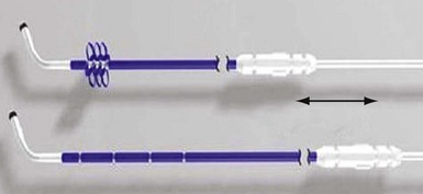
The concept of active-fixation leads in the coronary venous system has been brought to clinical practice with the Attain StarFix lead (Model 4195, Medtronic, Minneapolis), which has three sets of deployable lobes that fold out and protrude from the lead body just proximal to the tip (Fig. 4-18). These 12 circumferential lobes are extended by an external sliding-push tubing mechanism, and radiopaque markers are used to indicate whether one, two, or all three sets of lobes are extended or retracted. In a recent multicenter study of 408 implants, Crossley et al.71 found a very low lead dislodgment rate of 0.7% with stable electrical parameters over a mean follow-up of 23 months. Phrenic nerve capture with this unipolar lead required lead revision in 11 patients (2.5%). This reasonable performance must be weighed, however, against potential difficulties of extraction, which fortunately has not been a major issue in the other LV lead models to date. In this study of the active-fixation LV lead, 26 patients (6.4%) underwent an attempt at lead revision. In two patients, no attempt to remove the lead was made, and in the remaining 24 revisions, five attempts failed (21%). These patients had maximum implant duration of only 941 days. Of the seven patients who had a lead in situ for more than 1 year, four (57%) were unable to be extracted.
This study is similar to the experience of Nagele et al.,72 who encountered extraction difficulty caused by immobile lobes in two patients. The ability to un-deploy the lobes seems to be independent of the duration of implant and may be related to local branch vein thrombosis or an ingrowth of fibrous tissue through the lobe loops. Although both these studies were small and represented early experience with this lead, the difficulties with extraction of the StarFix lead contrast with the relative ease of extraction of chronic LV leads, even after extended periods since implantation.73
Design of CRT Leads
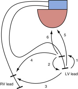
The interelectrode distance in bipolar CRT leads varies from 8 to 21 mm. The great advantage of bipolar leads is the option of programming between multiple different pacing electrode permutations, including true bipolar and extended bipolar configurations, with the option of selecting whether to use the LV tip or the LV ring electrode as the pacing cathode (Fig. 4-19). These programming options may be invaluable in the patient with posterolateral LV fibrosis or a large field of phrenic nerve capture, where an alternate pacing polarity may obviate the need for lead revision. True bipolar LV pacing also eliminates the problem of simultaneous right ventricular (RV) anodal capture, which can be seen in the setting of unipolar LV lead use and can sometimes partially undermine the benefit of LV pacing.74 Anodal capture from the RV ring or coil electrode can hinder proper CRT delivery by eliminating the ability to stimulate the left before the right ventricle, and occasionally by leading to absent LV pacing if the pacing output is inadvertently programmed below the true LV capture threshold, because RV anodal capture is mistaken for LV cathodal capture during threshold testing.75
No significant differences have been noted in the short-term and long-term complication rates after CRT implantation among the various leads and CRT systems commercially available.76
 ICD Leads
The development of the implantable cardioverter-defibrillator was a revolutionary step in the history of medicine.77 Sudden-death prevention became an achievable goal, initially in those who had survived cardiac arrest or malignant ventricular arrhythmias,78 but then in patients at risk of dying suddenly (primary prevention).79,80 Modern ICD systems are extremely sophisticated devices, frequently combined with CRT capability, that feature advanced rhythm-discrimination software, antitachycardia pacing (ATP) during capacitor charging, and high-voltage biphasic shocks, all in a pectorally implanted device of 40 cc or less. Advances in pulse generator technology and reliability are important but of limited relevance if progress cannot be matched in ICD lead design, development, and particularly durability. The reductionist view of ICD leads as simply being “pacemaker leads with additional shock coils” ignores the exponential rise in complexity as more components are added. This complexity puts pressure on long-term reliability in a device expected to cope repeatedly with 800-V high-current discharges and move with the heartbeat 37 million times annually. As longer follow-up data are published on both older and newer ICD leads, despite the innovations and developments in recent years, clearly this most vulnerable part of the ICD system continues to be prone to late failure.81–84
Historical Evolution of ICD Leads
Epicardial patches placed through thoracotomy were the leads first used in human ICD systems.77 The pulse generators in these systems were large and required placement in an abdominal pocket. Shock energy was delivered through a free-floating 12F nonpacing endovascular titanium spring coil that served as the anode, with the patch as the cathode. Sensing was accomplished initially by epicardial patches (or apical cup electrode in the first implant), but this sensing mechanism proved to be unreliable, and dedicated epicardial and endocardial leads were adopted early. These first-generation ICD systems had a high risk of complications, particularly in the large endovascular coil, including superior vena cava thrombosis, coil fracture, insulation failure, and coil retraction into the subclavian vein caused by lack of a lead anchoring sleeve.
Consequently, the second-generation ICD devices in the late 1980s were fully epicardial systems, with shock delivery between two epicardial patches and tachyarrhythmia sensing through an epicardial lead. Epicardial patches also had problems, however, including an ongoing infection and pericarditis risk,85 a possible adverse effect on transthoracic external defibrillation threshold, and a perioperative mortality of up to 4% at implantation in these patients, who were generally at high risk for thoracotomy or median sternotomy.86,87 These patch electrodes also displayed poor in vivo durability over time, with a failure rate of up to 28% at 4 years. More than half of patients with obvious lead failure or fracture were asymptomatic. The epicardial pace/sense leads incorporated in these systems were also suspect, with a failure rate of 14.1% at 8.5 years in one study, with lead fracture accounting for half these failures.88 In contrast to patch failure, patients with epicardial pace/sense lead failure were likely to develop multiple inappropriate ICD shocks from oversensing.89
By the early 1990s, advances in pulse generator design and technology allowed miniaturization for infraclavicular pectoral implantation, although this would require an entirely endocardial defibrillation, sensing, and pacing lead system. The initial transvenous leads were implanted with the pulse generator in an abdominal pocket, and the leads were tunneled subcutaneously from their pectoral vascular insertion site down to the abdomen. Such leads, including the Transvene family (Medtronic), were initially based on coaxial pacing lead platforms. Their development added ATP capability to ICD systems, but also new lead-related problems. Apart from the large bulk of these leads (up to 12F), predisposing to venous occlusion and subclavian crush,90 lead failure was frequent, demonstrating a progressive late incidence related to both conductor fracture and insulation defects.91 Addressing these problems required paradigm shifts in lead body design as well as advancements in materials technology, which ushered in the modern era of multilumen, narrow-caliber transvenous ICD leads.
ICD Lead Structure
The basic elements in pacing leads are also found in transvenous ICD leads: conductors, insulation, electrodes, fixation mechanisms, and connector terminals. In addition, however, ICD leads contain the high-voltage circuitry that links the pulse generator with one or two high-voltage shock coils located on the lead body (Fig. 4-20). One of these coils is located in the right ventricle, a variable distance proximal to the tip pace/sense electrode, whereas the other coil, if present, is positioned on the part of the lead located in the superior vena cava.
Two basic lead body architectures can be used to incorporate all these elements into an ICD lead. First, the coaxial structure, a design essentially borrowed from the pacing platform of the same name, consists of concentric coiled conductors (to tip electrode, ring electrode, and shock coils) layered inside one another and separated by intervening layers of insulation, with the whole assembly housed in an outer covering layer of insulation. The innermost coil connected down to the tip conductor contained a lumen for stylet insertion that assisted with endocardial lead implantation. The best known examples of this design were the Medtronic Transvene and the Ventritex TVL families of ICD leads, first used in the early 1990s. Although initial reports were positive,92 subsequent longitudinal data showed that these leads were prone to early and late failure, caused by a combination of conductor and insulation problems.83,91 Whether these failures were mainly related to the limited durability of the conductor and insulation (polyurethane 80A) materials, or resulted from an inherent weakness of the bulky coaxial architecture in situations of increased complexity as found in ICD leads, will never be known; this design was no longer in use by the late 1990s.
The second main paradigm for ICD lead structure, and still the dominant architecture for modern ICD leads, is the multilumen design, in which parallel cable and coil conductors run to the tip, with ring and shock electrodes in separate channel lumens, all within a single frame of insulation; some models also have additional, empty decompression lumens. The conductor to the tip electrode is conventionally coiled and contains the central lumen for stylet insertion. The coil also permits the transfer of torque when the implanting physician rotates the pace/sense connector terminal pin to deploy an active-fixation helix at the distal lead tip. Each conductor, both cable and coil, is invested with an inner layer of insulation, typically of fluoropolymer type, and the entire lead body is encased in a further outer insulation layer (see Fig. 4-3).
ICD Lead Sensing Design
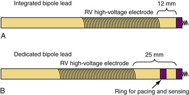
Sensing function is critical in ICD systems to allow for accurate rhythm discrimination and to prevent inappropriate shocks from oversensing as well as failure of tachyarrhythmia treatment caused by undersensing. Therefore, unipolar ICD leads were not developed because of the prohibitive risk of oversensing noncardiac potentials, such as pectoral and diaphragmatic myopotentials. Bipolar ICD lead sensing can be arranged according to one of two paradigms: integrated bipolar and dedicated bipolar (also called true bipolar) designs. Sensing in integrated bipolar leads occurs between the tip electrode and the RV shock coil, which doubles as the sensing anode, the distal extent of which is located 6 to 15 mm proximal to the tip. By comparison, dedicated bipolar leads additionally include a conventional ring electrode (the anode) 10 to 15 mm back from the tip, similar to a bipolar pacing lead (Fig. 4-21). The additional electrode means that an extra conductor is required in dedicated bipolar leads, but the smaller anode in these leads confers superior sensing performance with reduced far-field oversensing.93,94
The larger sensing anode (the distal shock coil) in integrated bipolar leads may be of particular concern in patients with small right ventricles, where the proximal end of the coil may extend across the tricuspid anulus and thereby pose a risk of far-field atrial oversensing.93 Integrated bipolar leads may be more prone to oversensing high-frequency respirophasic noise transients (i.e., diaphragmatic myopotentials), which may cause pacing inhibition and inappropriate shocks.95 The increased current density at the smaller anode of a dedicated bipolar lead does, however, increase the likelihood of anodal myocardial stimulation in CRT systems in which LV pacing is programmed in an “extended bipolar” fashion, with the RV ring doubling as the LV pacing anode,75 although in the current era of bipolar LV leads and pacing vector programmability, this is less of a concern.
The main theoretical advantage of integrated bipolar leads, apart from their greater simplicity (which may reduce the chance for component failure), relates to the smaller distance between the RV shock coil in these leads and the RV apex, because there is no intervening ring electrode between the shock coil and the lead tip. This is known as the pullback distance, and data suggest a modestly improved defibrillation threshold with shorter pullback distance,96,97 although this was more important before the current era of high-output, biphasic devices and greater defibrillation safety margins. Theoretical concerns about differences in R-wave amplitudes between the two lead designs have not been borne out by comparative studies,98 but some studies suggest longer sensing latency98 with integrated bipolar leads, as well as the potential for undersensing of postshock ventricular fibrillation, presumably from local myocardial stunning around the shock coil and its proximity to the tip cathode.99,100 This phenomenon was not seen when the shock coil was more than 6 mm from the tip electrode. However, in terms of sensing de novo ventricular fibrillation, no significant differences have been demonstrated between the two lead platforms,101 and both are in clinical use today, although dedicated bipolar systems are implanted more frequently.
Conductors
As with pacing leads, similar materials are used in ICD lead conductor construction, with MP-35N being the dominant metal alloy employed. As outlined earlier, its advantages include its corrosion and fracture resistance, but MP-35N–based conductors can still fracture at points of high stress (e.g., costoclavicular ligament). Recent testing suggests that this risk may be related to the presence of contaminant titanium inclusions, although this is controversial.102 In ICD systems, however, low-resistance conductors are essential to minimize voltage drops across the lead during high-voltage shock delivery. This requirement mandates the use of composite wire technology in which individual conductor strands combine higher-resistance MP-35N with a low-resistance metal such as silver in one of two patterns. The DFT pattern (see Fig. 4-5, A) produces conductor strands that are generally formed into coils, whereas in the DBS pattern (see Fig. 4-5, B), strands are twisted into multifilar braided cables (Fig. 4-22). The latter are particularly important in ICD leads because they have very high tensile strength and are more fracture resistant than coils.
Failed ICD leads frequently demonstrate intact high-voltage cables with fractured pace/sense coil conductors. One conductor coil strand is generally required, as outlined earlier, to create a lumen for stylet insertion and to permit active-fixation helix deployment. However, the use of multiple parallel cables in a multilumen ICD lead design produces a stronger lead of smaller diameter than would be possible if only coiled conductors were used (as in the now-obsolete coaxial configurations). Each cable generally is housed in its own lumen of the multilumen lead by coating it with stiff, fluoropolymer insulation, preventing abrasion and damage to the soft, silicone-based insulation of the lead body (see Fig. 4-3). Decompression spaces, either within the lumen that houses a conductor or as separate channels in the housing insulation, may reduce the stress on the conductors, particularly in the setting of repeated lead flexion.
Electrodes and High-Voltage Coils
The high-voltage defibrillation shock coil is the defining feature of the ICD lead. All models include at least one shock coil, wrapped around the distal lead body, 5 to 6 cm in length and positioned in the right ventricle, whereas dual-coil leads have a second shock coil located either 17 cm or 21 cm proximal to the shaft end of the RV coil, with this superior vena cava (SVC) coil being slightly longer, 7 to 8 cm (see Fig. 4-20). The RV coil serves as the defibrillation anode or cathode during phase 1 of a biphasic shock, depending on how the ICD is programmed to deliver high-voltage therapy, with the SVC coil and active pulse generator casing together serving as the other shock cathode or anode. With single-coil ICD leads, the pulse generator solely functions as the second high-voltage electrode. Dual-coil leads may assist in lowering the defibrillation threshold (DFT), although the improvement in DFT with the addition of an SVC coil may be modest and of greater benefit when the electrical impedance during single-coil shock delivery is higher.103 Because the high-voltage shock vector plays a role in DFT, some ICDs permit programming changes to eliminate either the SVC coil or the pulse generator itself from the shocking circuit, thereby improving the DFT in certain patients. Shocking coil–only leads are also available for implantation in the coronary sinus or azygous vein, or subcutaneously around the left thorax to improve the shock vector in patients with an elevated DFT and unreliable defibrillation with standard shock configurations.
The materials used in shock coil construction are generally platinum-iridium alloy or platinum alloy–clad tantalum, because titanium coils produce metallic oxides during high-voltage shocks that prevent their use in ICD leads. Polarization also affects the design of shock electrodes, as it does for pacing electrodes, but unlike the situation described earlier with pacing leads, fractally coating the shock coils does not improve defibrillation efficacy.104 However, some data suggest that iridium oxide coating may improve lead porosity and reduce polarization, even to the point of seeing a clinically meaningful reduction in DFT.105,106
Insulation
Although silicone rubber may be biostable and flexible enough to be used as the dominant material for ICD lead body insulation, its softness and high frictional coefficient make lead implantation difficult if the outermost surface of the ICD lead is silicone. Outer coverings of polyurethane may address this disadvantage to some extent, but the long-term mechanical risks related to silicone’s softness remain, as well as its susceptibility to abrasion and cold flow, and require the use of thicker silicone layers and thus increased lead caliber. This weakness is particularly marked at high-stress points such as at the costoclavicular ligament or in the pocket next to the pulse generator, where harsh local mechanical forces can lead to progressive insulation abrasion and local silicone thinning at pressure points. If lead insulation is sufficiently thinned or denuded that a low-impedance dielectric is created, particularly where a high-voltage conductor strand closely opposes the metal casing of the pulse generator in the device pocket, a short circuit with arcing can result during shock delivery, leading to ineffective defibrillation and permanent damage to the lead, the ICD circuitry, or both.107
As mentioned in the section on pacing leads, newer insulation materials are being developed for specific application in cardiac device leads, including one already in clinical use, Elast-Eon (Aortech Biomaterials, Clayton, Victoria, Australia). This substance is a hybrid copolymer composed of near-equal amounts of silicone and polyurethane and, in extensive laboratory experience, combines advantages of each.39 A family of pacing and ICD leads uses this material as an outer insulator (Optim, St. Jude Medical), but as yet no leads use this material for the primary lead body insulation.
ICD Lead Connector Terminals
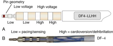
Eventually, industry-wide standardization occurred in ICD systems, such that the pace/sense coil conductor terminates in a standard IS-1 pacing pin that is placed in the IS-1 port of the ICD header, and each high-voltage shock coil terminates in a standard DF-1 (ISO-11318) connector pin. In a dual-coil ICD lead, therefore, three tails ending in one IS-1 pin and two DF-1 pins emerge from a trifurcation yoke attached to the main lead body (Fig. 4-23). Three separate connector ports are found on the ICD header to accommodate the trifurcated end of a dual-coil ICD lead (one IS-1 port and two DF-1 ports). The yoke and lead tails of the ICD lead are subject to insulation and conductor failure, just as in the rest of the lead system. They also increase pocket bulk and may contribute to erosion risk, particularly in the setting of a dual-chamber or biventricular device system, with atrial and LV leads also present. Additional abandoned lead ends might also be present in the device pocket, if nonfunctional or redundant leads remain in place in the setting of lead failure or device upgrade. Besides increasing pocket bulk and interaction between device system components, the greater number of connector pins in a standard ICD lead allows inadvertent connector pin reversal in the device header, and the thick fibrous tissue that frequently encapsulates the lead trifurcation yoke can make a generator change or system revision more challenging. The development of the new IS-4/DF-4 standard connector pin has allowed the integration of two DF-1 high-voltage terminals and one bipolar IS-1 pace/sense terminal, all into one connector pin (Fig. 4-24). This new design addresses the mechanical issues associated with current multiterminal ICD leads, but the long-term reliability of these connector pins is currently unknown.108 In addition, this all-in-one connector pin design precludes the ability to replace a single component of the ICD lead, such as the pace/sense or a shocking coil component, in the setting of pace/sense malfunction or elevated DFT.
Extraction Considerations
Increasingly, ICD systems are being implanted in younger patients with evolving indications outside the context of acquired cardiomyopathy. Channelopathies, arrhythmogenic RV dysplasia, congenital cardiac abnormalities, and sarcoidosis are indications for implant that affect younger patients, often children, who are expected to live with their ICD leads (since generators are changed at regular intervals) over their lifetime. Because ICD lead failure rates continue to accrue over time with current lead and materials technology,81 and lead infection can occur at any time without warning,109 lead manufacturers and physicians must give due consideration to this aspect of device therapy at implant. In addition, abandoned sterile leads are increasingly being removed to allow for reduced intravascular hardware burden, avoidance of inappropriate oversensing,110 and potentially increased long-term venous patency.111
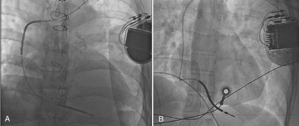
Lead extraction, even with the modern tools and expertise,112 remains a potentially hazardous endeavor,113,114 particularly in young patients with long-standing dual-coil ICD leads, in which tissue ingrowth into the interstices between the helical turns of the shock coil wire may be causing dense, fibrous adhesions and tissue encapsulation of the lead body (Fig. 4-25). With some data indicating that defibrillation efficacy may not be significantly improved with the addition of the SVC coil,115 one approach is to consider implanting only single-coil ICD leads in patients expected to have longer implant duration.116 However, the real solution lies in the manufacture of shock coils that are easier to extract.
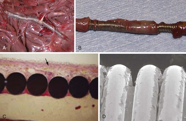
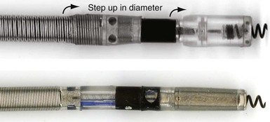
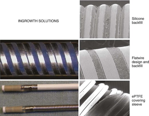
All newer ICD lead bodies are isodiametric, with the same or a smaller maximal external diameter as proceeding from the proximal to the distal end of the lead (Fig. 4-26), and are 8-Fr size or smaller, which already improves the ease of extraction over previous transvenous ICD lead systems. Manufacturers also have taken different approaches to the problem of shock coil adhesion to the venous and cardiac walls102 (Fig. 4-27). Silicone backfilling of the interstices between the coils has been used in Medtronic leads to reduce fibrous tissue ingrowth. This approach may be effective117 but is limited by the surface area of the outer curvature of the round coil strands; the interstices cannot be fully obliterated because a large, exposed coil surface area is required for effective defibrillation. In Biotronik and St. Jude Medical leads, use of flatwire technology allows complete backfilling of the interhelix turns with silicone, allowing for a completely isodiametric shock coil segment while still reducing fibrous tissue ingrowth, as demonstrated in animal testing.102 A third strategy, employed in Boston Scientific leads, is to cover the defibrillation coils with a thin, encapsulating jacket of semiporous expanded polytetrafluoroethylene (ePTFE; Gore-Tex, Gore and Associates, Flagstaff, Ariz). As with all fluoropolymers, this material is abrasion and tear resistant as well as biostable, but it has been molecularly modified to make it semiporous. This allows for free fluid and ion flow so as not to significantly alter high-voltage electrical conductance during shocks from the underlying defibrillation coils. Consequently, no significant difference in clinical defibrillation efficacy has been demonstrated with the use of ePTFE coils.118 In the setting of an integrated bipolar sensing ICD lead and additional abandoned leads in the right ventricle, mechanical interactions between the large RV coil and adjacent lead materials may occasionally result in sensed electrical artifacts. Oversensing from this type of lead-on-lead interaction may be reduced or eliminated if the metal strands of the RV coil are covered by an ePTFE sleeve.110 The real advantage of the semiporous sleeve, however, is that cellular migration cannot occur into the covered underlying coil interstices, thus reducing tissue ingrowth into, and local adherence of, the shocking coils over time. This has made ICD lead extraction easier in animal models, compared with an identical lead without covering sleeves.117 Recent clinical data have corroborated the potential benefit of modified ICD lead shock coils to improve the ease of extraction.119
ICD Lead Failure
The ICD lead is one of the most complex and vulnerable parts of the ICD system, and lead failure is a significant problem (Box 4-1). ICD lead failure, perhaps more so than with pacing lead failure, can lead to sudden death. This can occur not only by loss of pacing support in pacemaker-dependent patients, but as most often seen, also by causing recurrent inappropriate shocks due to oversensing of lead noise. These shocks can induce ventricular fibrillation, which the system may then not be able to defibrillate successfully.120 Early data from the transvenous lead experience held great promise,121 but late lead failure was seen at longer-term follow-up across all lead designs and manufacturers.81 Patient-related factors, such as excessive upper body activity, can contribute to ICD lead failure, as can procedural factors at implant, including subclavian (rather than cephalic) access,122,123 rough handling, traumatic transvenous insertion, overtorquing of active-fixation helices, and kinking of lead loops in the pocket. However, none of these factors is positively identified in most cases; the difficulty in extracting ICD leads (possibly with additional lead damage during its extraction) means that the failure mechanism usually remains obscure. A systematic solution to this problem must involve better ICD lead design and manufacture, with advances in materials technology.
Box 4-1
Symptoms and Signs of Lead Problems
The Transvene family (Medtronic) of coaxial ICD leads had a structural failure rate of 38% at 8 years,83 which was more often caused by fracture of the outer high-voltage coil conductor than disruption of the polyurethane 80A insulation. Despite changes in design and materials, however, newer generations of ICD leads are also prone to late failure. Kleemann et al.81 found that cumulative survival of 990 ICD leads implanted between 1992 and 2005 was only 60% at 8 years, mainly from insulation defects, including in silicone-based leads. One in five leads implanted for a decade or longer failed. This study was weighted toward the older lead models, however, and 95% of implants were through subclavian access, which may have affected failure rates and mechanisms.
In an industry-wide push for increasing miniaturization, small-caliber ICD leads were introduced in the mid-2000s. Again, although early data gave no cause for alarm,124 more recently125 the small-caliber (6.6F) Sprint Fidelis lead (Models 6930/6931/6949/6948, Medtronic) has been identified as much more prone than other contemporary lead models to early and late failure, usually presenting with conductor fracture, noise oversensing, and inappropriate shocks. Initial failure rate was 1.29% at 21 months,126 but risk appears to increase with time, up to 5.7% to 12.1% at 3 years,127–129 a failure rate of 3.75% per year, versus 0.58% per year or less for other contemporary ICD lead models.129,130 The mechanism in most cases is a fracture of the pace/sense hexafilar cathode conductor, either proximally, near the lead anchoring sleeve, or distally, near the anode ring electrode.102,131 Although no longer being implanted, the problem of failure with this lead is ongoing because of the large number of patients with this model in place.
 Conclusion
1 Wieneke H, Konorza T, Erbel R, Kisker E. Leadless pacing of the heart using induction technology: a feasibility study. Pacing Clin Electrophysiol. 2009;32:177-183.
2 Santini M, Cappato R, Andresen D, et al. Current state of knowledge and experts’ perspective on the subcutaneous implantable cardioverter-defibrillator. J Interv Card Electrophysiol. 2009;25:83-88.
3 Mond HG, Hunt D, Vohra J, Sloman JG. Cardiac pacing: memories of a bygone era. Pacing Clin Electrophysiol. 2008;31:1192-1201.
4 Breivik K, Ohm OJ, Engedal H. Long-term comparison of unipolar and bipolar pacing and sensing, using a new multiprogrammable pacemaker system. Pacing Clin Electrophysiol. 1983;6:592-600.
5 Mond H, Sloman G. The small-tined pacemaker lead: absence of dislodgement. Pacing Clin Electrophysiol. 1980;3:171-177.
6 Richardson JV, Wright CB, Ehrenhaft JL. Tined transvenous endocardial electrodes: results of a randomized prospective study. Ann Thorac Surg. 1981;31:289.
7 Snow N. Elimination of lead dislodgement by the use of tined transvenous electrodes. Pacing Clin Electrophysiol. 1982;5:571-574.
8 Kruse IM. Long-term performance of endocardial leads with steroid-eluting electrodes. Pacing Clin Electrophysiol. 1986;9:1217-1219.
9 Mond H, Stokes K, Helland J, et al. The porous titanium steroid-eluting electrode: a double-blind study assessing the stimulation threshold effects of steroid. Pacing Clin Electrophysiol. 1988;11:214-219.
10 Mehra R, Furman S. Comparison of cathodal, anodal, and bipolar strength-interval curves with temporary and permanent pacing electrodes. Br Heart J. 1979;41:468-476.
11 Secemsky SI, Hauser RG, Denes P, Edwards LM. Unipolar sensing abnormalities: incidence and clinical significance of skeletal muscle interference and undersensing in 228 patients. Pacing Clin Electrophysiol. 1982;5:10-19.
12 Zimmern SH, Clark MF, Austin WK, et al. Characteristics and clinical effects of myopotential signals in a unipolar DDD pacemaker population. Pacing Clin Electrophysiol. 1986;9:1019-1025.
13 Echeverria HJ, Luceri RM, Thurer RJ, Castellanos A. Myopotential inhibition of unipolar AV sequential (DVI) pacemaker. Pacing Clin Electrophysiol. 1982;5:20-22.
14 Schuchert A, Cappato R, Kuck KH, Meinertz T. Programmable polarity: effects on pacing and sensing of bipolar steroid-eluting leads. Pacing Clin Electrophysiol. 1996;19:2099-2102.
15 Mond HG. Unipolar versus bipolar pacing: poles apart. Pacing Clin Electrophysiol. 1991;14:1411-1424.
16 Helguera ME, Pinski SL, Maloney JD, et al. Durability of bipolar coaxial endocardial pacemaker leads compared with unipolar leads. Cleve Clin J Med. 1994;61:25-28. quiz 80-22
17 Wiegand UK, Bode F, Bonnemeier H, et al. Incidence and predictors of pacemaker dysfunction with unipolar ventricular lead configuration: can we identify patients who benefit from bipolar electrodes? Pacing Clin Electrophysiol. 2001;24:1383-1388.
18 Breivik K, Danilovic D, Ohm OJ, et al. Clinical evaluation of a thin bipolar pacing lead. Pacing Clin Electrophysiol. 1997;20:637-646.
19 Mond HG, Grenz D. Implantable transvenous pacing leads: the shape of things to come. Pacing Clin Electrophysiol. 2004;27:887-893.
20 Belott PH, Rizo-Patron C, Brownstein SL, et al. Clinical experience with passive-fixation coradial bipolar endocardial pacing leads. Thinline clinical investigators. Pacing Clin Electrophysiol. 1998;21:2291-2299.
21 Tang C, Yeung-Lai-Wah JA, Qi A, et al. Initial experience with a co-radial bipolar pacing lead. Pacing Clin Electrophysiol. 1997;20:1800-1807.
22 Gammage MD, Lieberman RA, Yee R, et al. Multi-center clinical experience with a lumenless, catheter-delivered, bipolar, permanent pacemaker lead: implant safety and electrical performance. Pacing Clin Electrophysiol. 2006;29:858-865.
23 Bai R, Kam R, Ching CK, et al. Implantation of lumenless pacing leads at the inter-atrial septum and right ventricular outflow tract with deflectable catheter-sheath. J Huazhong Univ Sci Technol Med Sci. 2008;28:639-644.
24 Kenny D, Walsh KP. Noncatheter-based delivery of a single-chamber lumenless pacing lead in small children. Pacing Clin Electrophysiol. 2007;30:834-838.
25 Chakrabarti S, Morgan GJ, Kenny D, et al. Initial experience of pacing with a lumenless lead system in patients with congenital heart disease. Pacing Clin Electrophysiol. 2009;32:1428-1433.
26 Kazama S, Nishiyama K, Machii M, et al. Long-term follow-up of ventricular endocardial pacing leads: complications, electrical performance, and longevity of 561 right ventricular leads. Jpn Heart J. 1993;34:193-200.
27 Stokes K. Implantable pacing lead technology. IEEE Eng Med Biol Mag. 1990;9:43-49.
28 Tyers GF, Mills P, Clark J, et al. Bipolar leads for use with permanently implantable cardiac pacing systems: a review of limitations of traditional and coaxial configurations and the development and testing of new conductor, insulation, and electrode designs. J Invest Surg. 1997;10:1-15.
29 Kruse I, Peters P, Ryden L. A new transvenous lead for both atrial and ventricular pacing. Pacing Clin Electrophysiol. 1983;6:953-956.
30 Raymond RD, Nanian KB. Insulation failure with bipolar polyurethane pacing leads. Pacing Clin Electrophysiol. 1984;7:378-380.
31 Antonelli D, Rosenfeld T, Freedberg NA, et al. Insulation lead failure: is it a matter of insulation coating, venous approach, or both? Pacing Clin Electrophysiol. 1998;21:418-421.
32 Bruck SD, Mueller EP. Materials aspects of implantable cardiac pacemaker leads. Med Prog Technol. 1988;13:149-160.
33 Phillips R, Frey M, Martin RO. Long-term performance of polyurethane pacing leads: mechanisms of design-related failures. Pacing Clin Electrophysiol. 1986;9:1166-1172.
34 Byrd CL, McArthur W, Stokes K, et al. Implant experience with unipolar polyurethane pacing leads. Pacing Clin Electrophysiol. 1983;6:869-882.
35 Stokes K, Urbanski P, Upton J. The in vivo auto-oxidation of polyether polyurethane by metal ions. J Biomater Sci Polym Ed. 1990;1:207-230.
36 Wiggins MJ, Wilkoff B, Anderson JM, Hiltner A. Biodegradation of polyether polyurethane inner insulation in bipolar pacemaker leads. J Biomed Mater Res. 2001;58:302-307.
37 Lim KK, Reddy S, Desai S, et al. Effects of electrocautery on transvenous lead insulation materials. J Cardiovasc Electrophysiol. 2009;20:429-435.
38 De Voogt WG. Pacemaker leads: performance and progress. Am J Cardiol. 1999;83:187D-191D.
39 Jenney C, Tan J, Karicheria A, et al. A new insulation material for cardiac leads with potential for improved performance. Heart Rhythm. 2005;2:S318-S319.
40 Parsonnet V, Villanueva A, Driller J, Bernstein AD. Corrosion of pacemaker electrodes. Pacing Clin Electrophysiol. 1981;4:289-296.
41 Mugica J, Duconge B, Henry L, et al. Clinical experience with new leads. Pacing Clin Electrophysiol. 1988;11:1745-1752.
42 Molajo AO, Bowes RJ, Fananapazir L, et al. Comparison of vitreous carbon and Elgiloy transvenous ventricular pacing leads. Pacing Clin Electrophysiol. 1985;8:261-265.
43 Adler S, Spehr P, Allen J, Block W. Chronic animal testing of new cardiac pacing electrodes. Pacing Clin Electrophysiol. 1990;13:1896-1900.
44 Hirshorn MS, Holley LK, Hales JR, et al. Screening of solid and porous materials for pacemaker electrodes. Pacing Clin Electrophysiol. 1981;4:380-390.
45 Mugica J, Henry L, Attuel P, et al. Clinical experience with 910 carbon tip leads: comparison with polished platinum leads. Pacing Clin Electrophysiol. 1986;9:1230-1238.
46 Moracchini PV, Cornacchia D, Bernasconi M, et al. High impedance low energy pacing leads: Long-term results with a very small surface area steroid-eluting lead compared to three conventional electrodes. Pacing Clin Electrophysiol. 1999;22:326-334.
47 Berger T, Roithinger FX, Antretter H, et al. The influence of high versus normal impedance ventricular leads on pacemaker generator longevity. Pacing Clin Electrophysiol. 2003;26:2116-2120.
48 Bolz A, Hubmann M, Hardt R, et al. Low polarization pacing lead for detecting the ventricular-evoked response. Med Prog Technol. 1993;19:129-137.
49 Erdinler I, Akyol A, Okmen E, et al. Long-term follow-up of pacemakers with an autocapture pacing system. Jpn Heart J. 2002;43:631-641.
50 Luria D, Gurevitz O, Bar Lev D, et al. Use of automatic threshold tracking function with non-low polarization leads: risk for algorithm malfunction. Pacing Clin Electrophysiol. 2004;27:453-459.
51 MacGregor DC, Wilson GJ, Lixfeld W, et al. The porous-surfaced electrode: a new concept in pacemaker lead design. J Thorac Cardiovasc Surg. 1979;78:281-291.
52 Djordjevic M, Stojanov P, Velimirovic D, Kocovic D. Target lead–low threshold electrode. Pacing Clin Electrophysiol. 1986;9:1206-1210.
53 Mond HG, Stokes KB. The steroid-eluting electrode: a 10-year experience. Pacing Clin Electrophysiol. 1996;19:1016-1020.
54 Radovsky AS, Van Vleet JF. Effects of dexamethasone elution on tissue reaction around stimulating electrodes of endocardial pacing leads in dogs. Am Heart J. 1989;117:1288-1298.
55 De Groot JR, Schroeder-Tanka JM, Visser J, et al. Clinical results of far-field R-wave reduction with a short tip-ring electrode. Pacing Clin Electrophysiol. 2008;31:1554-1559.
56 Fung JW, Sperzel J, Yu CM, et al. Multicenter clinical experience with an atrial lead designed to minimize far-field R-wave sensing. Europace. 2009;11:618-624.
57 Kertes P, Mond H, Sloman G, et al. Comparison of lead complications with polyurethane tined, silicone rubber tined, and wedge tip leads: clinical experience with 822 ventricular endocardial leads. Pacing Clin Electrophysiol. 1983;6:957-962.
58 Hidden-Lucet F, Halimi F, Gallais Y, et al. Low chronic pacing thresholds of steroid-eluting active-fixation ventricular pacemaker leads: a useful alternative to passive-fixation leads. Pacing Clin Electrophysiol. 2000;23:1798-1800.
59 Geyfman V, Storm RH, Lico SC, Oren JW. Cardiac tamponade as complication of active-fixation atrial lead perforations: proposed mechanism and management algorithm. Pacing Clin Electrophysiol. 2007;30:498-501.
60 Van Herendael H, Willems R. Contralateral pneumothorax after endocardial dual-chamber pacemaker implantation resulting from atrial lead perforation. Acta Cardiol. 2009;64:271-273.
61 Vlay SC. Complications of active-fixation electrodes. Pacing Clin Electrophysiol. 2002;25:1153-1154.
62 Li H, Helland J. In vitro evaluation of new design lead anchoring sleeves. Pacing Clin Electrophysiol. 1992;15:2005-2010.
63 Brown S. Connectors for implantable pacemaker leads. Pacing Clin Electrophysiol. 1980;3:620-621.
64 Doring J, Flink R. The impact of pending technologies on a universal connector standard. Pacing Clin Electrophysiol. 1986;9:1186-1190.
65 Tyers GF, Sanders R, Mills P, Clark J. Analysis of set screw and side-lock connector reliability. Pacing Clin Electrophysiol. 1992;15:2000-2004.
66 Cleland JG, Daubert JC, Erdmann E, et al. The effect of cardiac resynchronization on morbidity and mortality in heart failure. N Engl J Med. 2005;352:1539-1549.
67 Bristow MR, Saxon LA, Boehmer J, et al. Cardiac-resynchronization therapy with or without an implantable defibrillator in advanced chronic heart failure. N Engl J Med. 2004;350:2140-2150.
68 Purerfellner H, Nesser HJ, Winter S, et al. Transvenous left ventricular lead implantation with the Easytrak lead system: the European experience. Am J Cardiol. 2000;86:157K-164K.
69 Linde C, Abraham WT, Gold MR, et al. Randomized trial of cardiac resynchronization in mildly symptomatic heart failure patients and in asymptomatic patients with left ventricular dysfunction and previous heart failure symptoms. J Am Coll Cardiol. 2008;52:1834-1843.
70 Beshai JF, Grimm RA, Nagueh SF, et al. Cardiac-resynchronization therapy in heart failure with narrow QRS complexes. N Engl J Med. 2007;357:2461-2471.
71 Crossley GH, Exner D, Mead RH, et al. Chronic performance of an active-fixation coronary sinus lead. Heart Rhythm. 2010;7:472-478.
72 Nagele H, Azizi M, Hashagen S, et al. First experience with a new active fixation coronary sinus lead. Europace. 2007;9:437-441.
73 Hamid S, Arujuna A, Khan S, et al. Extraction of chronic pacemaker and defibrillator leads from the coronary sinus: laser infrequently used but required. Europace. 2009;11:213-215.
74 Freedman RA, Petrakian A, Boyce K, et al. Performance of dedicated versus integrated bipolar defibrillator leads with CRT-defibrillators: results from a prospective multicenter study. Pacing Clin Electrophysiol. 2009;32:157-165.
75 Thibault B, Roy D, Guerra PG, et al. Anodal right ventricular capture during left ventricular stimulation in CRT-implantable cardioverter defibrillators. Pacing Clin Electrophysiol. 2005;28:613-619.
76 Nof E, Gurevitz O, Carraso S, et al. Comparison of results with different left ventricular pacing leads. Europace. 2008;10:35-39.
77 Mirowski M, Reid PR, Mower MM, et al. Termination of malignant ventricular arrhythmias with an implanted automatic defibrillator in human beings. N Engl J Med. 1980;303:322-324.
78 Connolly SJ, Hallstrom AP, Cappato R, et al. Meta-analysis of the implantable cardioverter defibrillator secondary prevention trials. AVID, CASH and CIDS studies. Antiarrhythmics vs Implantable Defibrillator Study. Cardiac Arrest Study Hamburg. Canadian Implantable Defibrillator Study. Eur Heart J. 2000;21:2071-2078.
79 Moss AJ, Zareba W, Hall WJ, et al. Prophylactic implantation of a defibrillator in patients with myocardial infarction and reduced ejection fraction. N Engl J Med. 2002;346:877-883.
80 Bardy GH, Lee KL, Mark DB, et al. Amiodarone or an implantable cardioverter-defibrillator for congestive heart failure. N Engl J Med. 2005;352:225-237.
81 Kleemann T, Becker T, Doenges K, et al. Annual rate of transvenous defibrillation lead defects in implantable cardioverter-defibrillators over a period of >10 years. Circulation. 2007;115:2474-2480.
82 Ellenbogen KA, Wood MA, Shepard RK, et al. Detection and management of an implantable cardioverter defibrillator lead failure: incidence and clinical implications. J Am Coll Cardiol. 2003;41:73-80.
83 Dorwarth U, Frey B, Dugas M, et al. Transvenous defibrillation leads: high incidence of failure during long-term follow-up. J Cardiovasc Electrophysiol. 2003;14:38-43.
84 Luria D, Glikson M, Brady PA, et al. Predictors and mode of detection of transvenous lead malfunction in implantable defibrillators. Am J Cardiol. 2001;87:901-904.
85 Chevalier P, Moncada E, Canu G, et al. Symptomatic pericardial disease associated with patch electrodes of the automatic implantable cardioverter defibrillator: an underestimated complication? Pacing Clin Electrophysiol. 1996;19:2150-2152.
86 Echt DS, Armstrong K, Schmidt P, et al. Clinical experience, complications, and survival in 70 patients with the automatic implantable cardioverter/defibrillator. Circulation. 1985;71:289-296.
87 Gartman DM, Bardy GH, Allen MD, et al. Short-term morbidity and mortality of implantation of automatic implantable cardioverter-defibrillator. J Thorac Cardiovasc Surg. 1990;100:353-357. discussion 357-359
88 Almassi GH, Olinger GN, Wetherbee JN, Fehl G. Long-term complications of implantable cardioverter defibrillator lead systems. Ann Thorac Surg. 1993;55:888-892.
89 Daoud EG, Kirsh MM, Bolling SF, et al. Incidence, presentation, diagnosis, and management of malfunctioning implantable cardioverter-defibrillator rate-sensing leads. Am Heart J. 1994;128:892-895.
90 Gallik DM, Ben-Zur UM, Gross JN, Furman S. Lead fracture in cephalic versus subclavian approach with transvenous implantable cardioverter defibrillator systems. Pacing Clin Electrophysiol. 1996;19:1089-1094.
91 Hauser RG, Cannom D, Hayes DL, et al. Long-term structural failure of coaxial polyurethane implantable cardioverter defibrillator leads. Pacing Clin Electrophysiol. 2002;25:879-882.
92 Golino A, Pappone C, Panza A, et al. Clinical experience with the transvenous Medtronic Pacer Cardioverter Defibrillator (PCD) system. Tex Heart Inst J. 1993;20:264-270.
93 Weretka S, Michaelsen J, Becker R, et al. Ventricular oversensing: A study of 101 patients implanted with dual chamber defibrillators and two different lead systems. Pacing Clin Electrophysiol. 2003;26:65-70.
94 Gradaus R, Breithardt G, Bocker D. ICD leads: design and chronic dysfunctions. Pacing Clin Electrophysiol. 2003;26:649-657.
95 Sweeney MO, Ellison KE, Shea JB, Newell JB. Provoked and spontaneous high-frequency, low-amplitude, respirophasic noise transients in patients with implantable cardioverter defibrillators. J Cardiovasc Electrophysiol. 2001;12:402-410.
96 Rashba EJ, Bonner M, Wilson J, et al. Distal right ventricular coil position reduces defibrillation thresholds. J Cardiovasc Electrophysiol. 2003;14:1036-1040.
97 Lang DJ, Heil JE, Hahn SJ, et al. Implantable cardioverter defibrillator lead technology: Improved performance and lower defibrillation thresholds. Pacing Clin Electrophysiol. 1995;18:548-559.
98 Frain BH, Ellison KE, Michaud GF, et al. True bipolar defibrillator leads have increased sensing latency and threshold compared with the integrated bipolar configuration. J Cardiovasc Electrophysiol. 2007;18:192-195.
99 Callans DJ, Swarna US, Schwartzman D, et al. Postshock sensing performance in transvenous defibrillation lead systems: analysis of detection and redetection of ventricular fibrillation. J Cardiovasc Electrophysiol. 1995;6:604-612.
100 Natale A, Sra J, Axtell K, et al. Undetected ventricular fibrillation in transvenous implantable cardioverter-defibrillators: prospective comparison of different lead system-device combinations. Circulation. 1996;93:91-98.
101 Goldberger JJ, Horvath G, Donovan D, et al. Detection of ventricular fibrillation by transvenous defibrillating leads: Integrated versus dedicated bipolar sensing. J Cardiovasc Electrophysiol. 1998;9:677-688.
102 Haqqani HM, Mond HG. The implantable cardioverter-defibrillator lead: principles, progress, and promises. Pacing Clin Electrophysiol. 2009;32:1336-1353.
103 Lubinski A, Lewicka-Nowak E, Zienciuk A, et al. Comparison of defibrillation efficacy using implantable cardioverter-defibrillator with single- or dual-coil defibrillation leads and active can. Kardiol Pol. 2005;63:234-241. discussion 242-243
104 Gradaus R, Bocker D, Dorszewski A, et al. Fractally coated defibrillation electrodes: is an improvement in defibrillation threshold possible? Europace. 2000;2:154-159.
105 Niebauer MJ, Wilkoff B, Yamanouchi Y, et al. Iridium oxide–coated defibrillation electrode: reduced shock polarization and improved defibrillation efficacy. Circulation. 1997;96:3732-3736.
106 Niebauer MJ, Yamanouchi Y, Hills D, et al. Voltage dependence of ICD lead polarization and the effect of iridium oxide coating. Pacing Clin Electrophysiol. 2000;23:818-823.
107 Sweeney MO. Exploding implantable cardioverter defibrillator. J Cardiovasc Electrophysiol. 2001;12:1422-1424.
108 Hauser RG, Almquist AK. Learning from our mistakes? Testing new ICD technology. N Engl J Med. 2008;359:2517-2519.
109 Klug D, Balde M, Pavin D, et al. Risk factors related to infections of implanted pacemakers and cardioverter-defibrillators: results of a large prospective study. Circulation. 2007;116:1349-1355.
110 Cooper JM, Sauer WH, Garcia FC, et al. Covering sleeves can shield the high-voltage coils from lead chatter in an integrated bipolar ICD lead. Europace. 2007;9:137-142.
111 Zartner PA, Wiebe W, Toussaint-Goetz N, Schneider MB. Lead removal in young patients in view of lifelong pacing. Europace. 2010;12:714-718.
112 Wazni O, Epstein LM, Carrillo RG, et al. Lead extraction in the contemporary setting: the Lexicon Study: an observational retrospective study of consecutive laser lead extractions. J Am Coll Cardiol. 2010;55:579-586.
113 Hauser RG, Katsiyiannis WT, Gornick CC, et al. Deaths and cardiovascular injuries due to device-assisted implantable cardioverter-defibrillator and pacemaker lead extraction. Europace. 2010;12:395-401.
114 Saad EB, Saliba WI, Schweikert RA, et al. Nonthoracotomy implantable defibrillator lead extraction: results and comparison with extraction of pacemaker leads. Pacing Clin Electrophysiol. 2003;26:1944-1950.
115 Rinaldi CA, Simon RD, Geelen P, et al. A randomized prospective study of single-coil versus dual-coil defibrillation in patients with ventricular arrhythmias undergoing implantable cardioverter defibrillator therapy. Pacing Clin Electrophysiol. 2003;26:1684-1690.
116 Cooper JM, Stephenson EA, Berul CI, et al. Implantable cardioverter-defibrillator lead complications and laser extraction in children and young adults with congenital heart disease: implications for implantation and management. J Cardiovasc Electrophysiol. 2003;14:344-349.
117 Wilkoff BL, Belott PH, Love CJ, et al. Improved extraction of ePTFE and medical adhesive modified defibrillation leads from the coronary sinus and great cardiac vein. Pacing Clin Electrophysiol. 2005;28:205-211.
118 Koplan BA, Weiner S, Gilligan D, et al. Clinical and electrical performance of expanded polytetrafluoroethylene–covered defibrillator leads in comparison to traditional leads. Pacing Clin Electrophysiol. 2008;31:47-55.
119 Hackler JW, Sun Z, Lindsay BD, et al. Effectiveness of implantable cardioverter defibrillator lead coil treatments in facilitating ease of extraction. Heart Rhythm. 2010;7:890-897.
120 Undavia M, Fischer A, Mehta D. Fatal outcome in a pacemaker-dependent patient. Pacing Clin Electrophysiol. 2009;32:550-553.
121 Fahy GJ, Kleman JM, Wilkoff BL, et al. Low incidence of lead-related complications associated with nonthoracotomy implantable cardioverter-defibrillator systems. Pacing Clin Electrophysiol. 1995;18:172-178.
122 Roelke M, O’Nunain SS, Osswald S, et al. Subclavian crush syndrome complicating transvenous cardioverter-defibrillator systems. Pacing Clin Electrophysiol. 1995;18:973-979.
123 Kron J, Herre J, Renfroe EG, et al. Lead- and device-related complications in the antiarrhythmics versus implantable defibrillators trial. Am Heart J. 2001;141:92-98.
124 Kupper B, Yee R, O’Hara G, et al. Do small (6.6 Fr) active and passive fixation defibrillation leads perform as well as larger sized leads? A multi-centre analysis. Europace. 2007;9:657-661.
125 Hauser RG, Kallinen LM, Almquist AK, et al. Early failure of a small-diameter high-voltage implantable cardioverter-defibrillator lead. Heart Rhythm. 2007;4:892-896.
126 Krahn AD, Champagne J, Healey JS, et al. Outcome of the Fidelis implantable cardioverter-defibrillator lead advisory: a report from the Canadian Heart Rhythm Society Device Advisory Committee. Heart Rhythm. 2008;5:639-642.
127 Faulknier BA, Traub DM, Aktas MK, et al. Time-dependent risk of Fidelis lead failure. Am J Cardiol. 2010;105:95-99.
128 Beukema RJ, Misier AR, Delnoy PP, et al. Characteristics of Sprint Fidelis lead failure. Neth Heart J. 2010;18:12-17.
129 Hauser RG, Hayes DL. Increasing hazard of Sprint Fidelis implantable cardioverter-defibrillator lead failure. Heart Rhythm. 2009;6:605-610.
130 Porterfield JG, Porterfield LM, Kuck KH, et al. Clinical performance of the St. Jude Medical Riata defibrillation lead in a large patient population. J Cardiovasc Electrophysiol. 2010;21:551-556.
131 Cannom DS, Fisher J. The Fidelis recall: how much pressure can the ICD world bear? Pacing Clin Electrophysiol. 2008;31:1233-1235.
* Disclosures: Dr. Haqqani is the recipient of a Training Fellowship from the National Health and Medical Research Council of Australia (544309) and the Bayer Fellowship from the Royal Australasian College of Physicians. Drs. Cooper and Epstein have received modest honoraria from Boston Scientific, Medtronic, St. Jude Medical, Biotronik, and Spectranetics.
[/level-membership-for-cardiovascular-category][not-level-membership-for-cardiovascular-category]
4 Engineering and Construction of Pacemaker and ICD Leads
Tremendous advances have occurred in implanted cardiac device therapy, from the evolution of pacemakers to the modern era of high-voltage defibrillation and resynchronization devices. Advances in the components, integrated circuitry, size, and software of the implantable pulse generator are readily apparent, but the revolutionary progress in the design and manufacture of device leads is often not appreciated. In any device system, the lead is the critical interface linking the pulse generator and the myocardium; it allows for communication of electrical signals from the heart to the pulse generator through the sensing circuitry, and in the reverse direction, it allows for bradycardia pacing or tachyarrhythmia therapy. Although leadless pacing1 and defibrillation2 device systems are being actively developed, leads clearly will remain an integral component of device therapy for the foreseeable future.
Pacing Leads
Historical Milestones in Development
Permanently implantable pacing leads evolved from the temporary pacing wires that were first used to provide bradycardia support.3 The initial permanent transvenous leads were unipolar and consisted of a basic conductor, an insulator, and a connector pin. The electrodes were large and polished with high-polarization properties, low electrode-tissue impedance, and excessive current drain. No lumen was present in these leads to allow for stylet insertion, so lead implantation was a long, difficult task. Also, no fixation mechanism was present, so lead displacement rates were high. The development of bipolar pacing leads minimized far-field oversensing,4 requiring a major reconsideration of lead body design and structure, because two longitudinal conductors needed to coexist inside the lead, separated only by a thin layer of insulation. This and subsequent increases in complexity required advances in materials science so as not to compromise reliability.
The development of passive-fixation tines was a huge step forward and dramatically reduced the rate of reoperation for lead dislodgement compared with existing flange-tipped pacing leads.5–7 Active-fixation helices were introduced subsequently and further improved the stability of implanted leads. Modern electrodes were developed with small geometric surface area but large effective area as a result of porous surfaces, and these optimized the trade-off between high current density and low polarization. Chronic threshold rises and late exit block were still major problems in cardiac pacing at that stage, however, and remained so until the revolutionary incorporation of an elutable dexamethasone reservoir into a porous-tip electrode, essentially eliminating this complication.8 Although this likely resulted from the glucocorticoid and not the redesigned porous titanium-tip electrode, this remained unproved until a pioneering randomized double-blind trial compared two otherwise identical leads and electrodes, with and without steroid elution.9 This unequivocally demonstrated the benefit was the result of the dexamethasone. Subsequent advances have included the universal standardization of connector pins (and consequently device headers), improving lead longevity through the use of better component materials, and improving sensing through the use of narrower bipoles.
Lead Structure And Polarity
The basic functions of any cardiac device lead—pacing and sensing—require conductors for current flow between the pulse generator and myocardium and insulators to prevent short-circuiting of this current. These elements may be configured in two ways. First, a pace/sense circuit may be composed of a lead containing one conductor that connects to a negatively charged tip electrode, the cathode, from which electrons flow through the myocardium and thoracic cavity back to the active, positively charged pulse generator (IPG), the anode (Fig. 4-1, A). Such a lead, with only one conductor and electrode, is called a unipolar lead because only one electrode is in contact with the heart (although it is part of a bipolar circuit). It has been established that pacing thresholds are lower at most pulse widths when the intracardiac pacing electrode is configured as the cathode rather than as the anode10 (see Chapter 1). Although once the only option, unipolar leads have largely been replaced by bipolar leads. The alternative system consists of a lead body containing two conductors (separated and surrounded by insulation) that connect to a cathode-tip electrode and an anode ring electrode located several millimeters more proximally (Fig. 4-1, B). The IPG is not an active electrode in a bipolar circuit, and such leads are said to have bipolar configuration.
Unipolar systems have a large interelectrode distance from the tip of the intracardiac lead to the IPG, and this large field of view makes them vulnerable to the oversensing of myocardial signals (T waves or electrograms from another chamber, known as “crosstalk”) and far-field nonmyocardial signals such as pacing artifacts (another form of crosstalk), skeletal myopotentials, and nonphysiologic electrical “noise” in up to 38% of patients.11 Electrical signal oversensing can have significant consequences on pacing behavior, including ventricular output inhibition and inappropriate mode switching caused by far-field ventricular oversensing on the atrial channel.12,13 Because of the additional consequence of inappropriate shock delivery if oversensing were to occur in an ICD, it is particularly important for ICD leads to have bipolar sensing circuitry. Since the IPG itself serves as one of the electrodes in a unipolar system, skeletal muscle capture and pectoral muscle stimulation may result in the setting of a higher programmed pacing output. Bipolar leads have been shown to have similar but slightly higher, acute and chronic stimulation thresholds to unipolar leads.4 Bipolar leads also carry an element of redundancy in that they can be used in either the bipolar or the unipolar configuration, as in isolated failure of the proximal, anodal conductor, with no demonstrated difference in performance between the two pacing configurations.14 In addition, the much lower amplitude of the bipolar pacing artifact greatly reduces the likelihood of crosstalk and oversensing. The great advantage of bipolar leads is related to their superior sensing properties. These factors have led to the near-universal adoption of the bipolar lead as the configuration of choice in cardiac device systems.15 The only potential disadvantage of bipolar leads is that reliability is lower than with the less complicated unipolar lead,16 although some studies have not supported this contention.15,17
However, insulation failure usually has negligible effects on unipolar lead performance, a clear reliability advantage. In terms of the structure of the lead body, the simple, single-conductor design of unipolar leads had to be modified to accommodate the greater number of components and increased complexity of the bipolar lead body. There are two main bipolar lead designs, coaxial and coradial (Fig 4-2). Coaxial leads have an inner conductor that extends down the length of the lead to the tip electrode, the cathode, arranged in a coil configuration with a central lumen to allow for passage of a stylet at implantation. This coil is covered by a cylindrical length of inner insulation, which in turn is wrapped by another coil conductor that also runs down the lead to the ring electrode, the anode. A second, outer layer of insulation and lead covering protect the ring conductor from the outside environment, thereby completing the design. Although this coaxial model has been the industry standard for pacing leads for many years, the resulting bulk and stiffness of this four-layer design are significant compared with the simpler unipolar leads. Coradial bipolar leads addressed some of these concerns with new conductor and insulator technology that was subsequently used in ICD lead design. In coradial leads, a single coil extends down the length of the lead (again with a central lumen to allow for stylet insertion) and consists of two parallel, alternating conductor strands, one of which connects to the cathode and the other to the anode. Each conductor strand is individually coated with a bonded layer of ethylene tetrafluoroethylene (ETFE) fluoropolymer insulation (originally by DuPont, Wilmington, Del), which serves to insulate each strand from the other, despite being intertwined. The single, two-component coil is surrounded by a single, outer insulation covering.18 These leads have comparable bulk (~5F diameter) and flexibility to unipolar leads, often with tines or a fixed, nonretractable helix to minimize size; electrical parameters and reliability have not been demonstrably inferior to coaxial leads.18–21
Defibrillator leads have even greater complexity, with two, three, or four conductors that connect to the pacing/sensing electrodes as well as to the high-voltage shocking coil(s), depending on the specific type of lead. Because of the prohibitive bulk that would result from a coaxial design with more than two conductors, ICD leads generally have a different type of structure, known as a multilumen design. This type of ICD lead consists of a long cylinder of insulating material, with separate internal channels running down its length (Fig. 4-3). Each conductor runs down an individual channel, usually with its own additional covering tube of insulation. The configuration and number of channels differ, depending on the number of conductors, the specific manufacturer, and whether air-filled channels are also incorporated into the design to improve lead handling and protect the conductors from flexion-related damage in the dynamic intracardiac and intravascular environment.
One other lead body structure worth mentioning are small (4.1F diameter), isodiametric, lumenless pacing leads (Model 3830 SelectSecure; Fig. 4-4). The lack of a central lumen and the use of a conductor cable (rather than coil) allows for increased insulation redundancy, high tensile strength, and reduced bulk. It also means that the active-fixation helix is nonextendable because there is no central coil conductor to transmit torque from the connector pin to extend or retract the helix. Fixation of such leads to the myocardium is achieved by turning the entire lead body. To enable implantation without a stylet, the lead is deployed through an 8.5F steerable catheter delivery system (SelectSite C304). Short-term results from this lead have been reasonable, with no signs of increased lead displacement or fracture risk.22,23 The small external diameter of this lead has been considered to be of some benefit in pediatric patients24 and patients with congenital heart disease,25 but the suggestion of a resulting improvement in chronic venous patency from the smaller size is yet to be substantiated in long-term follow-up. In addition, selective site pacing, in both the atria and the ventricles, is facilitated by the deflectable sheath, although steerable and preformed stylets can also be used with conventional leads to achieve this. No published experience with extraction of chronically placed lumenless leads exists, and the lack of a lumen to accommodate a lead-locking device may be a significant disadvantage of this design.
Conductors
Both the coaxial and the coradial bipolar pacing lead body designs have been in widespread use and proved to be relatively fracture resistant over time. This durability is at least partially related to the materials and design of the conductor elements used in pacing leads. One study found conductor fracture over a 17-year follow-up in 19 of 561 right ventricular pacing leads (3.4%) and then generally at points of high stress, such as at the lead anchoring sleeve and the costoclavicular ligament (subclavian crush).26 The basic material used for most conductors over the last 3 to 4 decades has been MP-35N (SPS Technologies, Cleveland), an alloy of nickel, cobalt, chromium, and molybdenum. The main advantage of MP-35N is its high strength and resistance to corrosion.27 Its main disadvantage is its high electrical resistance, but this has been overcome with the development of composite-wire conductors that incorporate low-resistance metals such as silver and stainless steel with high-strength materials such as titanium, platinum, and platinum-iridium alloy.
In pacing leads, these materials are generally incorporated into a drawn filled tube (DFT) composite-wire conductor strand consisting of a thick, strong body of MP-35N or titanium that has been filled with a central core of softer, low-resistance metal such as silver, often encased in a further outer shell of platinum alloy (Fig. 4-5, A). The DFT conductor strands are then formed into multifilar (i.e., multiple strands or filaments) coils with a central lumen in coaxial leads, as described earlier, or further coated in a layer of ETFE fluoropolymer before being arranged in bifilar coradial coils,28 again with a central lumen. The alternative way of forming a composite-wire conductor is the drawn brazed strand (DBS) method, generally consisting of six strands of a high-resistance material (e.g., MP-35N) that are tightly molded over a central strand of silver, such that the inner, low-resistance metal is forced between and around the strong outer strands (Fig. 4-5, B). This results in a low-resistance, durable composite conductor wire that can once again be formed into a multifilar coil for use in pacing leads.29 However, it is also used to form strong, multifilar, braided cables that are employed as the conductors for the high-voltage circuitry of ICD leads. DBS cables are discussed later.
Insulation
Pacing lead insulation is a critical and vulnerable component that is often the cause of lead failure.30,31 One of the problems with the major materials used for lead insulation (polyurethane, silicone rubber, fluoropolymers) is that they were not originally designed specifically for this purpose, and each has disadvantages when used as part of a biologic pacing system. They were incorporated by early lead engineers into their designs for lack of any purpose-built alternatives, and it is only recently that any viable, tailored alternatives have been developed.
Poly(ether)urethane is a synthetic, segmented polymer with very high tensile strength and resistance to mechanical abrasion. From a physical perspective, this means that a thinner layer of insulation can be used to cover the lead conductors, thereby reducing the overall lead diameter. Also, polyurethane has excellent lubricity and handling characteristics, with a low frictional coefficient, which can facilitate implantation of two or three lead systems by decreasing the physical interactions between the leads. However, polyurethane leads are stiffer and not fully biostable, being subject to in vivo polymer degradation that can cause insulation and late lead failure.32 The two main types of polyurethane are Pellethane 80A and Pellethane 55D (Upjohn, CPR Division, Torrance, Calif), with 80A particularly prone to biodegradation.
Two mechanisms of in vivo, biologically mediated degradation of polyurethane predominate: environmental stress cracking (ESC) and metal ion oxidation (MIO)33 (Fig. 4-6). When polyurethane is subjected to repeated mechanical stresses in the presence of surface-active agents provided by macrophages and α2-macroglobulin, parallel polymer molecules are disordered and interchain bonds weakened. This is the mechanism of ESC,34 manifesting as a deep surface cracking visible with electron microscopy, particularly at the anchoring sleeve and venous entry portions of the lead. By comparison, no mechanical stress is required for MIO to develop because this is a chemical reaction that occurs particularly at the conductor-insulator interface.35 Biologic oxidants, such as peroxide from surrounding inflammatory cells,36 can result in the release of metal cations from the conductor, especially cobalt and nickel ions. These cations cause oxidation of the soft zones in the polymer, starting at the α-carbon of the ether bond and resulting in chain break. The harder Pellethane 55D is much less susceptible to both ESC and MIO than 80A but is significantly stiffer. Nevertheless, the long-term performance of Pellethane 55D has been much better than Pellethane 80A, a material notoriously prone to failure.
Figure 4-6 Mechanisms of polyurethane insulation failure on electron microscopy.
(Courtesy St Jude Medical, Sylmar, Calif.)
Silicone rubber (polysiloxane) has none of the disadvantages of polyurethane. It is completely inert and biostable over extended periods and thus not vulnerable to MIO or ESC. Silicone is more flexible, which may decrease the risk of damage to cardiac structures, including lead perforation. It is also more thermally resistant to the effects of electrocautery, which can be a significant advantage during pulse generator replacement or system revision.37 Initially, a softer peroxide-catalyzed silicone rubber, MDX4-4515-50A, was used for pacing leads, but new versions with higher tensile strength and abrasion resistance have been developed. These include high-performance (HP) silicone, extra-tear-resistant (ETR) silicone, and Novus (Med-4719, Nusil Technologies, Carpinteria, Calif), produced by hybridizing HP and MDX4 silicone. Unfortunately, no variety of silicone rubber has the positive characteristics of polyurethane, including surface lubriciousness and ease of handling. Although these friction-related problems of silicone can be addressed by an outer layering of polyurethane, the main problem with silicone relates to its lower tensile strength and susceptibility to abrasion and tears (Fig. 4-7, A). This means that silicone insulation is more prone to damage during implantation and subsequent interactions in the device pocket, and that a thicker insulation layer must be used to maintain lead reliability, thereby increasing lead bulk. Also, as with glass, silicone is a fluid material and thus prone to a gradual flowing process away from pressure points, known as “cold flow,” which can lead to thinned, denuded, and abraded troughs or depressions adjacent to areas of thickened rubber polymer32 (Fig. 4-7, B).
Figure 4-7 Mechanisms of silicone rubber insulation failure.
(Courtesy St Jude Medical, Sylmar, Calif.)
The fluoropolymers polytetrafluoroethylene (PTFE) and ETFE (DuPont) have some of the advantages of both silicone and polyurethane, with good abrasion resistance and biostability.38 Unfortunately, their great stiffness excludes them from functioning as the primary insulating material in any lead, but they can be used, as outlined earlier, as a thin coat on conductor strands, particularly in coradial leads. This inner insulating layer can prevent electrical communication between conductor strands and can also protect them from interacting with an adjacent outer layer of polyurethane, thereby reducing MIO.
Recently, the development of a specific insulation material for cardiac leads has suggested that the deficiencies of the standard insulators in pacing leads may finally be addressed. The material is a copolymer hybrid composed of 48% silicone, 40% polyurethane hard segment, and 12% polyhexamethylene oxide soft segment; it is called Elast-Eon (Aortech Biomaterials, Clayton, Victoria, Australia). This blending of insulating materials results in the product having the strength, lubricity and abrasion resistance of polyurethane, but the flexibility and biostability of silicone.39 Early bench and clinical testing have been promising to date, with little evidence of cold flow, ESC, or MIO phenomena, the main weaknesses of silicone and polyurethane. The material has been used in the St. Jude Medical Optim family of pacing (Models 1888T and 2088T) and ICD leads (Durata), but no long-term data on its chronic performance are yet available.
Electrodes
The materials used for lead electrodes have evolved over the past 40 years and have included titanium, anodized platinum, platinum-iridium alloys, Elgiloy (an alloy of cobalt, iron, chromium, molybdenum, nickel, and manganese), and vitreous carbon. All these display relative inertness in vivo, which minimizes inflammatory reactions and corrosion over the long term. Minor corrosion is seen, however, with Elgiloy and platinum alloys when in situ for extended periods, although this is of uncertain clinical significance.40 While attempting to control for other differences, several human and animal studies have compared these materials, but the results are conflicting.41–44 In general, applications have been found for these materials in electrode composition, with most having reasonable in vivo performance and longevity, although vitreous carbon cathodes have particular strength, inertness, and long-term electrical reliability.45
More important than the precise material composition of electrodes seems to be their geometry, particularly the surface area. A large cathodal surface area in contact with the endocardium results in a low current density at the electrode-tissue interface and consequently a higher capture threshold. As tip electrodes were reduced in surface area, apart from better thresholds, higher tissue-electrode impedances were also seen, and this increased pulse generator longevity.46,47 Against this beneficial effect of a smaller electrode is the adverse effect on tissue polarization seen with a smaller electrode surface area. Polarization refers to the electrical afterpotential generated at the electrode-tissue interface by ionic movement induced by the pacing stimulus. At pacing pulse delivery, a layer of positively charged cations is attracted to and surrounds the negatively charged cathode (and a larger layer of negatively charged anions surrounds the cation layer), which opposes current flow from the pacing electrode. This polarization potential is recorded as an afterpotential following the stimulus artifact. To maximize the advantages of small-radius electrodes, yet minimize the disadvantage of the polarization effect more prominent with smaller electrode surface area, current electrodes are small in size but have a complex, porous microscopic surface (Fig. 4-8). Regardless of the method of achieving a complex, highly textured surface, such as coating the electrode with microspheres or a woven mesh of microscopic metallic fibers, the resulting large surface area has proved beneficial with regard to pacing and sensing performance.
Figure 4-8 Sintered porous electrode (left) and laser porous electrode (right).
(From Hirshorn MS, Holley LK, Skalsky M, et al: Characteristics of advanced porous and textured surface pacemaker electrodes. PACE 6:525-536, 1983.)
Titanium nitride–coated or iridium-coated cathodes with fractal surface structure achieve the goal of enhanced surface area with a negligible polarization signal48 (Fig. 4-9). Such electrodes have permitted the development of beat-by-beat automatic capture threshold and pacing output management systems that measure the evoked myocardial response following every pacing stimulus. By verifying myocardial capture for each paced beat, with the immediate delivery of a backup higher-output pulse if capture is lost (Fig. 4-10), the pacemaker can maintain a pacing output only marginally above the capture threshold, thereby prolonging pulse generator battery life.49 Another type of automatic threshold algorithm does not verify beat-to-beat capture, but performs an automatic threshold test daily and adjusts the pacing output accordingly (with larger safety margin above capture threshold). These types of automatic capture-detection algorithms can be unreliable in the setting of a significant polarization afterpotential, because a large polarization signal cannot be distinguished from the local myocardial evoked response.50
Electrodes implanted in myocardium elicit a strong foreign body granulomatous reaction that results in the formation of a local fibrous capsule at the lead tip, which can have a profound effect on electrical performance. Smooth-surfaced electrodes elicit the formation of a thick, electrically insulating capsule of fibrous and granulation tissue that may impede electrode fixation to the endocardium.51 Complex, porous electrodes, in contrast, are manufactured to have extremely small (20-50 µ in diameter) surface pores that allow for endocardial attachment by way of tissue ingrowth into these regions, which yields a mechanical advantage in addition to the electrical benefits mentioned earlier. A fibrous reaction also occurs with highly textured electrodes, but a lesser insulating effect is observed because the electrically active myocardium is closer to the electrode,51 resulting in improved electrical parameters over time.52
To curtail further the fibrous reaction elicited by the electrode and to decrease the incidence and magnitude of chronic threshold rises, a pharmacologic anti-inflammatory strategy was pursued with glucocorticoid-eluting porous electrodes (Fig. 4-11). These leads showed excellent long-term capture and sensing parameters, with a dramatic reduction in late exit block (i.e., loss of myocardial capture).8 In an elegant and seminal double-blind randomized trial, Mond et al.9 conclusively proved the beneficial effect of steroid elution by comparing two otherwise identical porous titanium electrodes, only one of which incorporated dexamethasone in its tip. There was no difference in capture threshold seen at implant. Although there was an expected late rise in threshold in the standard leads starting at 2 weeks, this was completely abolished in the steroid-eluting lead, both during the trial period and in long-term follow-up.53 Animal studies confirmed that the biologic basis of this electrophysiologic effect was through the glucocorticoid-induced attenuation of the inflammatory reaction, with thinner, less cellular fibrous capsules.54
Figure 4-11 Dexamethasone-eluting reservoirs in passive-fixation (A) and active-fixation (B) leads.
(Courtesy St Jude Medical, Sylmar, Calif.)
In bipolar leads, another factor affecting electrical performance, particularly far-field sensing, is the interelectrode distance between the tip cathode and the ring anode. Narrow-spaced bipolar electrodes in atrial leads have been shown to reduce far-field ventricular electrogram sensing without compromising atrial sensing.55 In a randomized trial that compared an atrial lead with a 1.1-mm tip-to-ring spacing (Model 1699T Optisense, St. Jude Medical) with a standard 10-mm spacing, the close-spaced bipole showed minimal far-field ventricular sensing at a sensitivity of 0.3 mV, compared to 30% 1-year incidence in the standard-bipole group.56 This translated into a large reduction in inappropriate mode switch events, from 23% in the control group to 4% in the narrow-bipole group.
Fixation Mechanisms
Initial pacemaker leads had no fixation mechanisms, so lead dislodgement rates were high. The first solutions to this problem were wedge-shaped flanges and fins, but these had limitations. The development of scalloped tines was the first robust solution to the problem of lead displacement,5 and comparisons with earlier methods of passive fixation were favorable.57 Tines are usually constructed from the same material as the covering insulation of the lead, typically silicone rubber, and protrude backward from the base of the tip electrode. Their orientation is designed to allow advancement of the lead for initial implantation but to prevent retraction and dislodgement by engaging the myocardial trabeculae of the right atrial appendage and right ventricular apex (Fig. 4-12, A).
Although passive-fixation tined leads perform well, with low rates of dislodgement, they are less reliable for pacing at nontraditional sites, and the development of active-fixation leads with a helix at the tip improved the options for pacing site selection (Fig. 4-12, B). These leads generally have an extendable-retractable screw made of platinum-iridium or similar alloy that is usually electrically active as part of the cathode. This terminal helix is deployed (i.e., extended out of lead) with clockwise rotation of the connector pin, which transmits torque via the central coil conductor to the helix mechanism at the other end of the lead. A small number of leads use a stylet-driven extension-retraction mechanism. Some smaller-diameter leads have a fixed helix that requires rotation of the entire lead body around the stylet for deployment into the myocardium. Steroid elution from a reservoir at the base of the helix helps to dampen the inflammatory reaction produced by traumatic engagement of the myocardium by the screw. Active- and passive-fixation leads perform similarly overall,58 with some differences related to their construction. Active leads tend to be easier to extract, whereas passive leads tend to have lower chronic thresholds with higher impedances that prolong pulse generator longevity. The clinician must always consider the potential for perforation59 and trauma to surrounding structures60 when using active-fixation leads.61
Lead Anchoring Sleeves
Securing the lead body to the fascia or muscle at the floor of the device pocket at implantation is an important step to prevent lead dislodgement. The sutures used must be fastened firmly but, given the relative fragility of lead insulation as previously outlined, must not be allowed to compromise the lead structure or integrity (Fig. 4-13). Although the anchoring sleeve provides a mechanism to achieve this balance, there has been little development in this area. After being tied down tightly, sleeves made of MDX silicone were found to produce much lower lead deformation than ETR silicone,62 but no long-term in vivo data are available. Suture sleeves that grasp the lead by snapping into place (rather than relying on circumferential deformation of sleeve by encircling suture) have been proposed but are not in current use.
