33 Electromagnetic Interference and CIEDs
 Electromagnetic Compatibility
International standards have been developed establishing the upper limit of permissible field intensities and protocols established to test CIEDs against possible interference. Regulatory agencies in the United States established recommendations to test for EMI in CIEDs.1 Draft recommendations are also available for guidance in the use of wireless technology.2
 Sources of Electromagnetic Interference
Sources of EMI can be classified according to type and spectral frequency of energy emitted, as well as the environment in which the source is encountered (Box 33-1). For clinical purposes, it is useful to recognize radiated and conducted sources of EMI.
Box 33-1
Documented Sources Of Electromagnetic Interference (Emi)
Electromagnetic Fields
Radiated EMI
Radiated EMI can result from energy emitted for communication purposes or as an unintended effect of other electrical activity (e.g., motor operation in an electric razor). Electromagnetic fields have both an electric field, measured in volts per meter (V/m), and a magnetic field. The magnetic flux density is measured in milliteslas (mT). Another common way to characterize an electromagnetic field is by the power density, or power per unit area. Power density can be expressed in milliwatts (mW) or microwatts (µW) per square centimeter (cm2). The unit used to measure how much radiofrequency (RF) energy is actually absorbed by the body is the specific absorption rate (SAR); it is usually expressed in watts per kilogram (W/kg) or milliwatts per gram (mW/g). Electromagnetic sources, for the purpose of examining medical device interactions, may be broadly divided into RF waves, with frequencies between 0 Hz and 450 MHz (e.g., electric power, radio/television transmitters, electrosurgical units, EAS systems), and microwaves, between 450 MHz and 12 GHz (e.g., radar transmitters, cellular telephones, two-way phones, microwave ovens) (Fig. 33-1).
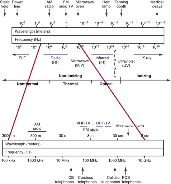
Figure 33-1 Electromagnetic spectrum.
(Modified from Moulder JP: Cellular phone antennas and health. http://www.mcw.edu/gcrc/cop/cell-phone-health-FAQ/toc.html.)
The frequency of the EMI determines the efficiency of energy coupling to the device and the resulting effect. The signal may be modulated in amplitude or frequency, and it may occur in bursts or single, long pulses. An RF carrier with amplitude modulation may induce voltages in the signal processing and detection circuitry of a CIED that can be misinterpreted as intracardiac signals.3 In other words, if the amplitude modulation has frequency components in the device’s physiologic passband, significant interference occurs. Electromagnetic fields may also cause interference with RF telemetry. Programming requires access codes to establish the telemetry link, parity checks of transmitted messages, and often simultaneous magnetic reed-switch closure by a steady magnetic field. Although the chance of modifying programmable parameters in a CIED is unlikely with current systems, integrity of the wirelessly transferred data may be affected.4
 Sources of Knowledge Regarding Electromagnetic Interference
Knowledge of EMI effects on implanted devices arises from several sources. Anecdotal reports highlight the possibility of interactions but provide little information regarding overall risk. The interaction may have depended on idiosyncratic programming or device malfunction. In the United States, the Center for Devices and Radiological Health of the Food and Drug Administration (FDA) maintains a database of reported incidents of deleterious interactions (MAUDE) that is searchable online.5 However, reporting is largely voluntary, and documentation is uneven. Case reports published in peer-reviewed journals (especially if they include a re-challenge in a controlled environment) can be most valuable.
Prospective studies can be performed in vitro (i.e., bench testing) or in vivo, using laboratory animals or patient volunteers. In vitro studies are performed with the implantable device submerged in a saline-filled tank (to emulate electrical properties of tissue) and the source of radiated EMI in close proximity. A multichamber heart/trunk simulator allows more realistic in vitro testing of devices.6 Anatomically based electromagnetic models of the human body allow the use of numerical modeling to quantify the relationship between an external electromagnetic field and the voltage induced in the leads of a CIED.7 Such modeling can greatly strengthen the clinical relevance of in vitro simulation studies. These investigations allow expeditious study of interactions among various EMI sources and devices. Multiple iterations of the experiment permit examination of the effects of distance, position, field strength, and device programming on the frequency and severity of the interaction. Although simulation studies predict interference in vivo, they do not match clinical exposures identically. Discrepancies may be related to the inability to replicate the strength and path of induced body fields, differences in body position and movements, modifications from shielding effects, and specific absorption rate of the body. The orientation of the air gap between the source and the saline tank (i.e., perpendicular vs. parallel) significantly influences the distance threshold for interaction.8
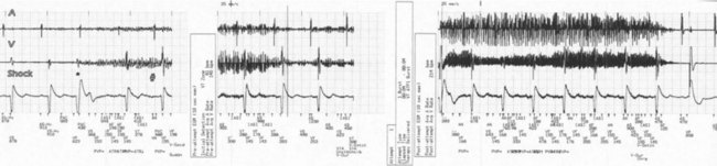
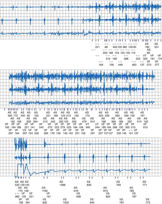
In a few high-risk circumstances (e.g., MRI), in vivo testing is first conducted in laboratory animals implanted with a pacemaker system. More frequently, in vivo simulation studies require controlled patient exposure to potential sources of EMI while the cardiac rhythm is monitored. Patient exposure studies clarify the clinical significance of in vitro interactions. However, because of the time and effort involved, the number of assessed permutations is, by necessity, limited. To avoid inadvertent bias, it is important to recruit patients who are representative of the general population with implanted devices. In vivo studies are complicated by many sources of EMI also interfering with real-time or Holter electrocardiogram (ECG) recordings. Bipolar asynchronous pacing pulses that do not elicit a QRS complex are particularly difficult to ascertain. Special recording techniques are often necessary. Furthermore, real-time telemetry between the implanted device and the programmer is often compromised by EMI, even when device function remains otherwise normal. Critical review of the literature suggests that some purported instances of EMI have resulted from this inconsequential phenomenon.9 Furthermore, the programmer wand placed directly over the device can act as an artificial shield. Analysis of annotated stored electrograms (EGMs), if available, is the ideal method to evaluate device behavior during exposure to potential sources of EMI (Fig. 33-2).
Protocols for testing of implantable cardiac devices to interactions with sources of EMI were updated by the American National Standards Institute and the Association for the Advancement of Medical Instrumentation in 2007.1 This voluntary standard addresses electromagnetic compatibility of pacemakers and ICDs and provides guidance for device testing. Increased traveling, the globalization and advancement of technology in addition to a rapid increase of the number of implanted devices also warrant a global, international approach for the management of device interactions. International standards for electromagnetic compliance are issued by the International Electrotechnical Commission (IEC) and by the European Committee for Electrotechnical Standardization (CENELEC).10,11
 Diagnosis of Electromagnetic Interference
 Pacemaker and ICD Responses to Electromagnetic Interference
Pacing Inhibition
Sustained pacing inhibition can be catastrophic in pacemaker-dependent patients (Fig. 33-3). Depending on the duration of inhibition and the emergence of escape rhythms, lightheadedness, syncope, or death could result. In pacemakers, protective algorithms make prolonged inhibition uncommon. Patients who are dependent on their ICD for bradycardia pacing may be more vulnerable to prolonged pacing inhibition from EMI. In ICDs, automatic adjustment of either the gain or the sensing threshold, according to the amplitude of the intrinsic R wave, ensures sensing of low-amplitude ventricular depolarization signals during ventricular fibrillation (VF) without oversensing of T waves and extracardiac signals. In the absence of sensed complexes, two potentially life-threatening diagnoses must be considered: asystole (requiring pacing) and fine VF (requiring amplifier gain adjustments for proper detection). To ensure the detection of VF, pacing onset triggers an increase in sensitivity in most devices. These very-high-sensitivity levels can promote oversensing of extracardiac signals. Oversensing perpetuates, because the absence of spontaneous large-amplitude escape beats maintains the high operating sensitivity. Asynchronous pacing may not occur in the absence of reliable ICD noise-reversion modes. Therefore, EMI-induced prolonged inhibition and spurious tachyarrhythmia detection become likely (see later discussion). Simulation studies of the interactions between sources of EMI and ICDs require creation of a “worst-case scenario” (inducing maximum sensitivity during continuous pacing).
Triggering of Rapid or Premature Pacing
Oversensing of EMI by the atrial channel of a pacemaker or ICD programmed to a tracking mode (DDD, VDD) can trigger ventricular pacing at or near the upper tracking rate limit. Alternatively, automatic mode switching may occur if this function is enabled (Fig. 33-4). In some pacemakers, detection of noise in the atrial channel can trigger a noise-reversion mode. Preferential detection of EMI does occur, because atrial sensitivity is usually programmed higher (more sensitive) than ventricular sensitivity. It is possible to observe rapid pacing caused by atrial oversensing as a patient approaches an electromagnetic field, followed by a period of ventricular oversensing (inhibition or mode reversion) as the field becomes stronger. If sustained, inappropriate pacemaker acceleration induced by atrial oversensing can cause palpitations, hypotension, or angina.
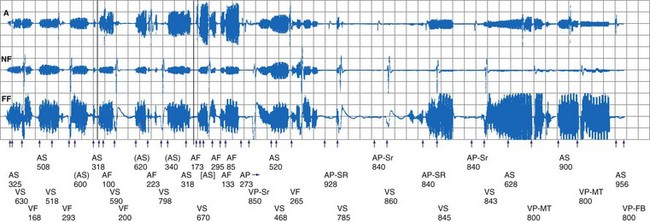
Figure 33-4 Spurious mode switch caused by atrial oversensing of EMI in patient with dual-chamber Guidant ICD.
Less frequently, EMI can induce rapid pacing through other mechanisms. For example, some sources of EMI can trigger rapid pacing (up to the sensor-triggered upper rate limit) by activating the sensor in minute ventilation (MV) pacemakers. The signal emitted by acoustomagnetic EAS systems is at the same frequency as the pulses used by some MV pacemakers to measure transthoracic impedance. MV pacemakers may also erroneously interpret the signals generated by certain monitoring and diagnostic equipment, including cardiac monitors, echocardiography equipment, apnea monitors, and respiration monitors, which also use bioelectric impedance measurements.12–14
Very strong electromagnetic fields could induce enough voltage in the lead or leads to directly capture the myocardium. For example, 58-kHz acoustomagnetic EAS systems are capable of inducing 3.7 V in pacemaker leads.15 Isolated premature paced beats (but no sustained rapid pacing) have been observed in patients. In vitro and in vivo animal studies16 have shown that application of 64-MHz RF power, required to produce MRI scans, can result in rapid pacing at pulsing periods between 200 and 1000 msec. Rapid pacing requires an intact lead connected to a pacemaker. Apparently, energy is coupled to the pacemaker defibrillation protection diodes or to the output circuit, bypassing the runaway protection mechanisms. Very rapid pacing could induce VF. Irregular rapid pacing at a rate of approximately 100 beats per minute (bpm) temporarily related to RF pulses during magnetic resonance imaging (MRI) was observed in a patient with a VVI pacemaker programmed at subthreshold output.17
Spurious Tachyarrhythmia Detection
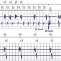
Electromagnetic interference signals can satisfy ICD tachyarrhythmia detection criteria and lead to spurious ICD discharges (Fig. 33-5). As noted, pacemaker-dependent patients can have concomitant inhibition of pacing. In a follow-up study of 341 ICD patients who received education regarding avoidance of sources of EMI, spurious tachyarrhythmia caused by EMI occurred five times in four patients.18 The incidence was 0.75% per patient-year of follow-up. In a study of 200 chronically implanted Medtronic ICDs with detection of VF, oversensing of EMI was the cause in three patients.19 Intermittent EMI can result in shock delivery if tachycardia detection fails to terminate between the self-limited EMI episodes.
Noise-Reversion Mode
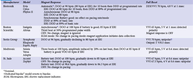
Pacemakers incorporate protective algorithms against prolonged inhibition from spurious signals (Table 33-1). A common response is transient reversion to asynchronous pacing. These algorithms are based on the fact that rapid frequencies are unlikely to represent myocardial activation. In most pacemakers, a noise-sampling or noise-interrogation window (also known as a relative refractory period) occupies the second part of the ventricular refractory period. Pacemakers do not respond to signals during the initial portion of the ventricular refractory period (i.e., ventricular blanking), which may or may not be programmable, and in some devices is adjusted automatically by the generator based on the strength and duration of the ventricular event. Signals recognized during the noise-sampling window cannot reset the lower rate timer, thus preventing inhibition, but they do affect other timing intervals, most importantly the ventricular refractory period. In some models, a noise-sampling period exists in both the atrial and the ventricular channel. Signals sensed in the noise-sampling period results in resetting of the noise-sampling window and extension of the blanking period. Repetitive triggering of the noise-sampling period eventually leads to asynchronous pacing. During simulation studies, a variable but narrow window of inappropriate pacing or inhibition is frequently observed at field or current strengths just below the reversion thresholds, because of intermittent oversensing. This phenomenon has little clinical significance during real-life EMI exposure. Occasional inhibition over a range of external field strengths is possible because EMI-induced body currents can fluctuate widely with changes in posture, respiratory phase, and other natural circumstances.20 Although transient asynchronous pacing is generally safe, it is not completely innocuous. Symptoms secondary to loss of atrioventricular (AV) synchrony and an irregular heartbeat can occur. Competition with the spontaneous rhythm can induce ventricular tachyarrhythmias if the pacing stimulus captures the ventricle during its vulnerable period. This is extremely uncommon in pacemaker patients, as attested to by the routine use of a magnet during clinic or transtelephonic pacemaker checks.
TABLE 33-1 Noise-Reversion and Electrical Reset Responses of Dual-Chamber Pacemakers Programmed DDDR
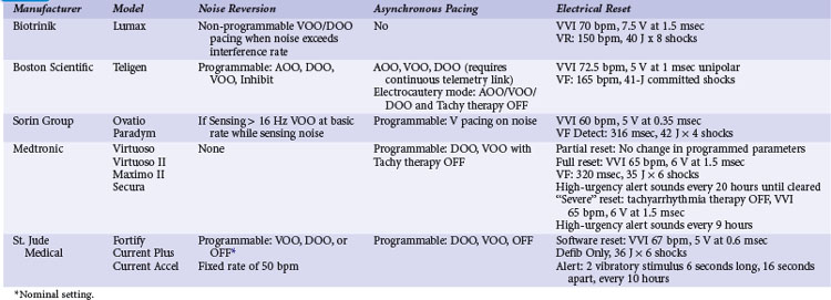
Implementation of noise-protection algorithms is more difficult in ICDs (Table 33-2). By design, these devices must be able to recognize the rapid rates of VF. Therefore, long refractory periods after sensed events are not feasible. Furthermore, asynchronous pacing is undesirable in patients who are vulnerable to reentrant ventricular arrhythmias.21 Newer Boston Scientific devices (Teligen, Cognis) utilize a Dynamic Noise Algorithm (DNA), which adjusts automatic gain control (AGC) settings in the presence of noise. Sorin devices (Ovatio, Paradym) also decrease sensitivity if noise is detected (signals sensed over 16 Hz). ICDs from Boston Scientific, Sorin, and St. Jude Medical provide programmable noise-reversion modes, but their performance against common sources of EMI is not well documented. Medtronic ICDs lack noise-reversion capabilities.
Electric (Power-On) Reset
Momentarily strong EMI, by inducing very high voltage within device circuits or triggering special microprocessor timers, may reset pacemakers and ICDs to operate in a mode different from the programmed mode. Electrosurgery and external or internal defibrillation are common causes of the reset phenomenon. In the reset mode, the pulse generator functions only with the basic factory-preset instructions (pacing mode and parameters) that are stored in the nonvolatile read-only memory (ROM), because communication between the microprocessor and the random-access memory (RAM), which contains the programmable settings, has been interrupted. Most DDD(R) pacemakers reset to the VVI mode (see Table 33-1). The reset mode does not revert back when EMI is discontinued. Resolution of the problem requires a specific programmer command. In some pulse generators, there is no response to magnet application in the reset mode. In some pacemakers, the pacing mode and rate are similar during electrical reset and elective replacement indicator (ERI). In other pacemakers (e.g., older St. Jude Medical devices), strong EMI can trigger a reset mode or ERI. In those cases, clearing the ERI message with the programmer restores normal function. In Medtronic pacemakers, two levels of electrical reset exist: partial and full. Partial reset tends to occur with less intense interference, preserving the programmed pacing mode and rates. Electrical reset can be differentiated from battery depletion by telemetric assessment of battery voltage and impedance. If reset was caused by EMI, the battery voltage should be normal (~2.8 V), and the battery impedance should be either normal or slightly raised according to battery age.
In ICDs, electrical reset generally results in a “shock box” configuration, with VVI pacing and maximum energy shocks (see Table 33-2). A special type of reset (called “hard reset” by St. Jude Medical, “cold reset” or “safety core mode” by Boston Scientific) can occur if there is damage to the ICD microprocessor or memory (e.g., from radiotherapy). This type of reset is irreversible and cannot be reverted by a programmer command. Prompt generator replacement is usually required.
Closure of the Reed Switch
Most pacemakers and some ICDs contain a magnetic reed switch that is closed by a 7 mT (Boston Scientific) to 1 mT (Medtronic) static magnetic field. This generally results in temporary asynchronous pacing in pacemakers and temporary suspension of tachyarrhythmia detection and therapy in most ICDs. Normal function returns as soon as the magnetic field dissipates. Older Guidant ICDs were deactivated by continuous application of a magnetic field for 30 seconds or longer. Reactivation required reapplication of the magnet for 30 seconds or longer or a programmer command. Guidant ICDs have been inadvertently deactivated by items that generate inconspicuous strong magnetic fields, such as magnetized screws,22 stereo speakers,22 and bingo wands,23 as well as by unadvised magnet application in health care settings.24 In later devices, this function was programmable and nominally disabled, and it is no longer available in the latest generation of Boston Scientific ICDs. In most contemporary ICDs, magnetic reed switch and its function has been largely replaced by other technologies (integrated solid-state detection, Boston Scientific; Hall effect sensor, Medtronic; telemetry coil, Sorin Group; GMR circuit, St. Jude Medical).
Transient suspension of antitachycardia pacing caused by reed-switch closure had been shown to occur frequently with older-generation ICDs. In a study of 46 patients with St. Jude ICDs (which keep a log of magnet reversions), nine unexplained inactivations occurred outside the medical environment (10% per patient-year of follow-up).25
Response to magnet application is also programmable in various devices to trigger specific behaviors, including storage of EGMs and event markers or replay of alert tones. Exposure to a strong magnetic field when these functions are activated can result in eccentric (but clinically inconsequential) device behavior.26 However, inadvertent asystole can occur when magnet application does not result in asynchronous pacing in pacemakers during electrosurgery.
Damage to Generator or Electrode-Myocardium Interface
Current devices incorporate elements (Zener diodes, thyristors) that protect the pacing output circuitry and sensing amplifiers by shunting excess energy away from the device. The Zener diode behaves as a short circuit as soon as the voltage exceeds a certain value, such as 10 to 15 V, that is substantially above the output voltage of the pulse generator. Other circuit designs can also limit the current flowing up the lead, but at the expense of inhibition of pacing output during the reception of large voltages.27
Interactions with Telemetry Function
Communication between the CIED and programmer is achieved by RF transmission via a wand. Once the “handshake” is complete and connection established with the programmer, further communication may be accomplished via wireless communication with certain devices. Wireless communication has also been increasingly used for home monitoring of device function and clinical status.28,29 Communication may be inhibited or greatly degraded if interference from external sources is present. These interactions may occur during device testing in the OR or clinic as well as potentially in the home.
Determinants of Electromagnetic Interference
The effects of EMI on pacemakers and ICDs depend on the intensity of the electromagnetic field, the frequency spectrum of the signal, the distance and positioning (angle) of the device relative to the source, the electrode configuration (unipolar or bipolar), nonprogrammable device characteristics, programmed settings, and patient characteristics (Box 33-2).
Electrical and magnetic fields decrease inversely with the square of the distance from the source. Devices from different manufacturers differ in susceptibility to various sources of EMI, depending on circuitry design. EMI from digital cellular telephones has largely been suppressed by incorporation of simple RF feedthrough filters to the circuitry. Interference is most likely when the antenna is placed over the device header. Neither the sensing electrodes near the distal tips of the leads, nor the coated lead body, is susceptible. A higher-programmed sensitivity level increases device susceptibility to EMI. Unipolar pacemakers are more vulnerable to EMI from sources in the lower range of the frequency spectrum, such as power lines.30 Left-sided unipolar CIEDs are particularly susceptible because of the larger loop for voltage induction between the lead and the generator. Sensing configuration loses importance at longer radiation wavelengths.
 Sources of Electromagnetic Interference
Daily Life
Cellular Telephones, Wireless Communication Devices, Personal Media Players
By the end of 2010, subscribers to mobile cellular phone services are expected to reach 5 billion worldwide. Although cell phones continue to be the most popular wireless communications devices, personal digital assistants (PDAs), laptop computers, wireless Internet connections, portable digital media players, and other appliances are being increasingly used for wireless voice, data, music, and video transmission. Assessment of the effects of cell phones on CIEDs has been complicated by the wide variety of technologies in use.31 Almost all current wireless telephones operate with digital technologies, although many can fall back to analog operation if their digital mode is not available. The Global System for Mobile (GSM) communications has become the predominant digital platform worldwide. Other digital technologies in use in the United States and elsewhere include North American Digital Cellular (NADC), also known as Time Division Multiple Access (TDMA-50 Hz); Code Division Multiple Access (CDMA); integrated Dispatch Enhanced Network (iDEN), a cell phone system that also serves as a walkie-talkie platform; and Personal Communication System (PCS). New third- and fourth-generation (3-G, 4-G) networks with increased speed for data transmission are being deployed. Wireless networks operate in the 800- to 960-MHz or the 1.8- to 2.5-GHz band. The power level used by a wireless telephone (and the consequent emitted electromagnetic field) fluctuates throughout the call, according to distance from the base station and the number of devices being used on the system at the same time. The maximal power of handheld phones is limited to 0.6 W in the United States and 2 W in Europe. Vehicle-mounted units can transmit at higher powers (up to 8 W), but they are not in common use by the general public.
Although isolated case reports have suggested the potential for severe interactions,32 most research indicates that deleterious interactions are unlikely to happen with normal cell phone use. Large-scale bench-testing studies of the effects of wireless telephones on pacemakers and ICDs have been conducted at the FDA’s Center for Devices and Radiological Health,33,34 the Medical Devices Bureau of Canada,35 and the University of Oklahoma’s Wireless Electromagnetic Compatibility Center.36,37 These studies encompassed several thousands of runs of telephone-device combinations and provided consistent results. Interference was nonexistent with the now-outdated analog telephones. The pulsed component of the transmission in digital cell phones was detectable by pacemaker sensing circuitry if the field was strong enough. PCS and similar technologies produced interactions in less than 1% of tests, whereas other digital technologies (GSM, TDMA) produced interference in 0% to 25% of tests. In all studies, just a few models were responsible for a disproportionately large number of interactions, and other models were largely immune. An older version of TDMA-11 technology (used only for specialized business applications such as trucking, delivery, and construction in the United States) accounted for most interactions with ICDs. Titanium casing and introduction of feedthrough filters, now common in modern pacemakers, made devices virtually immune to interference. Almost all interactions occurred at distances of less than 10 cm. Devices always reverted to normal operation when the phone was turned off.
Systematic investigations of the effects of cell phones in patients with pacemakers and ICDs have documented that severe interactions are improbable with most technologies during regular phone use. In a comprehensive multicenter study, Hayes et al.38 tested 980 patients with implanted pacemakers for potential interference with five types of telephones (one analog and four digital: NADC, TDMA-11, PCS, and CDMA). Telephones were tested in a simulated worst-case scenario; in addition, NADC telephones were tested during transmission to simulate actual use. Patients were monitored while the phones were held at the ipsilateral ear and in a series of maneuvers directly over the pacemaker. The incidence of any type of interference was 20% in the 5533 tests. Tracking of interference sensed in the atrial channel, asynchronous pacing, and ventricular inhibition were the most common reactions observed (14%, 7%, and 6%, respectively). Interference was least frequent with analog (2.5%) and PCS (1.2%) systems. Clinically significant EMI was observed in 7% of tests and was considered severe in 1.7%. There were no clinically significant EMI episodes when the telephone was placed in the normal position over the ear. The presence of feedthrough filters in the pacemakers almost abolished the risk of EMI (from 29% to 56% down to <1%).
In a study of 39 pacemakers, EMI was more common with portable 8-W GSM telephones than with handheld 2-W models (7% vs. 3% of tests); oversensing was more frequent at maximal than at nominal sensitivity (6% vs. 2% of tests).39 In a recent study of 100 patients with pacemakers from five manufacturers equipped with feedthrough filters testing a GSM cell phone with maximum power of 2 W in the standby, dialing, and operating mode, only two instances of ventricular inhibition were observed with the phone held directly over the pocket and the ventricular sensitivity programmed unipolar at 0.5 mV or less. Reprogramming of the sensitivity to 1 mV abolished the interaction in both cases.40 In another European study, 158 patients with pacemakers from one of seven manufacturers were tested for EMI using a GSM and PCS phone (max power 2 W vs. 1 W, operating frequency 900 MHz vs. 1800 MHz, respectively).41 The phones were placed over the device (as if carried in breast pocket), and EMI was evaluated while the device received a call (highest power emission). Device interaction was very rare and only occurred in four older devices with less advanced filters.
The GSM telephones did not induce inappropriate rapid pacing in patients with MV pacemakers42 or atrial oversensing in single-lead VDD pacemakers programmed at maximum atrial sensitivity.43 In a study of 95 children with a variety of pacemakers programmed to a worst-case scenario, GSM telephones did not induce significant interference.44 Clinical worst-case scenario testing has not disclosed significant interactions between ICDs and wireless digital telephones.44–47 Digital cell phones do not interfere with the detection of induced VF in the electrophysiology laboratory.47 Inconsequential intermittent loss of telemetered EGMs and surface ECGs and inscription of erroneous event markers (i.e., “pseudo-oversensing”) recorded via the programmer are common. Although this may have limited significance during a clinic visit, implications may be different if interaction occurred during the use of a remote home monitoring system. Effect of GSM phones were tested in vitro (three-chamber heart stimulator) as well as in vivo in a study to evaluate possible interactions with Biotronik pacemaker/ICD home monitoring system. A proprietary telemetry is used in these devices transmitting in the 402 to 405–MHz band with maximum power of 25 µW to communicate with the base unit within a 10-foot (3-m) distance. The base unit in turn transmits data via GSM cellular network to the monitoring center. No interactions were observed during in vitro testing, and there was 93% success in transmissions in vivo.48 Delay or loss of transmission was seen as result of EMI. Similar home monitoring systems are also available from several other manufacturers.
Portable media players, especially iPODs (Apple, Cupertino, Calif.) have been increasingly used (>270 million units sold worldwide). Because these units are frequently carried in the shirt pocket and close to the CIED, several studies addressed possible device interactions. While reproducible programmer telemetry interactions were common, these were clinically nonsignificant, and no other serious interaction was seen with modern pacemakers.49–52 Clinically significant device interaction caused by strong magnetic field may occur, however, if portable headphones are held close to a CIED.53 Telemetry interactions may have important implications in the use of home monitoring systems, and these need to be addressed in the future.
Although cell phones can potentially interfere with the function of implanted devices, this interference does not pose a health risk when telephones are placed over the ear. Maintaining an activated cell phone at least 6 inches (15 cm) from the device prevents interactions. The FDA has issued simple recommendations to minimize the risks. Patients should avoid carrying their activated cell phone or iPOD in a breast or shirt pocket overlying a CIED. A wireless telephone in use should be held to the ear opposite the side where the device is implanted. A survey of 1567 Japanese patients with implanted pacemakers revealed that, although 94% were right-handed, 41% used the left hand preferentially to hold a wireless telephone.54 Not-so-obvious reasons for choosing one hand versus the other to hold the phone included hearing loss on one side (10%) and use of the opposite hand for dialing or writing memos (22%). At least in some patients, apparently the hand preferentially used to hold the wireless telephone should be considered when selecting the site for pacemaker implantation.
Limited in vitro and in vivo testing has suggested that 3-W GSM telephones do not interfere with the function of an implantable ECG loop recorder.55 A single case report suggested interference between an ILR and the handheld activator if an iPOD is operating in proximity to the devices.56
In an in vitro study, PDAs connected to a hospital wireless local area network (WLAN) using the 802.11b protocol did not interfere with a variety of pacemakers and ICDs manufactured by Guidant, Medtronic, or St. Jude Medical.57
Electronic Article Surveillance Devices
Also known as antitheft devices or “antishoplifting gates,” EAS devices are ubiquitous in retail stores, libraries, and office buildings. More than 1 million systems have been installed worldwide. The transmitter in these devices emits an electromagnetic field that is designed to interact with a “tag” in an unpurchased item. As a result of the interaction, the tag emits a signal that is detected by the receiver. Customers are exposed to an electromagnetic field as they walk through the gate, which typically consists of a pair of transmitter and receiver pedestals. EAS systems differ greatly in the frequency and strength of their emitted fields. Available technologies include high-frequency systems (operating beyond 900 MHz), swept RF systems (operating at 2 to 10 MHz), low-frequency acoustomagnetic systems (30-132 kHz), and electromagnetic systems (20 Hz to 18 kHz). These technologies serve different retailers’ needs in terms of area covered, cost, detection, and “false alarm” rate, and they are not strictly interchangeable. The general consumer cannot differentiate these systems by their external appearance. Electromagnetic fields from these devices have the potential to induce interference signals in the sensing circuit of implanted cardiac devices. A sentinel report described a patient with complete heart block and a Ventak (CPI/Guidant) AV ICD in an abdominal pocket who developed multiple shocks and near-fatal inhibition of pacing on exposure to an acoustomagnetic EAS system.58 Provocative testing with similar equipment in a controlled environment reproduced the interaction. The maximum distance at which ventricular oversensing occurred was 30 cm. When sensitivity was reprogrammed from “nominal” to “least sensitive,” the interaction occurred only at closer proximity.
Prospective studies have clarified the incidence, severity, and risk factors for EMI from EAS systems. An in vitro study showed that 20 of 21 pacemaker models reacted to the field of an acoustomagnetic EAS system, and 10 reacted to an electromagnetic system.59 Responses included inhibition and noise reversion. Interference occurred when the simulator was within 33 cm of the transmission panel for the acoustomagnetic system, or 18 cm for the electromagnetic system. Mugica et al.60 exposed 204 patients with pacemakers to two different EAS systems (acoustomagnetic at 58 kHz and electromagnetic at 73 Hz) for up to 30 seconds. Interference occurred in 17% of patients and was twice as likely with the acoustomagnetic system. Atrial tracking, asynchronous pacing, and single-beat inhibition were observed. All the interactions were transient and deemed benign.
McIvor et al.15 studied the effects of six EAS devices of three types (magnetic audiofrequency, swept radiofrequency, acoustomagnetic) in 50 patients with pacemakers and 25 patients with ICDs from seven different manufacturers. One exposure protocol mimicked the most common real-life situation, walking at a normal pace midway between the gates. A “worst-case scenario” protocol required the patients to lean against the transmitter gate with the body parallel and then perpendicular to the transmitter. Interactions occurred with 48 pacemakers, almost exclusively with acoustomagnetic systems. No pacemaker reacted to the swept RF systems. Only two patients had transient asynchronous pacing while exposed to an electromagnetic system. The frequency of interactions with the acoustomagnetic system increased with the duration and closeness of the exposure: 16% when walking through the gates and 96% when leaning against the pedestal. Transient asynchronous pacing was the most common response, followed by atrial oversensing with tracking, ventricular oversensing with inhibition, and “voltage-induced” paced beats. Changing the sensing configuration from unipolar to bipolar, or programming a lower sensitivity setting, did not abolish the interactions but limited them to closer distances from the center of the gate. There were no instances of false tachyarrhythmia detection, but the ICDs were not programmed to pace during the testing.
Groh et al.61 studied the interaction between ICDs and two electromagnetic and one acoustomagnetic EAS devices in 169 patients. No spurious detections occurred during a 10- to 15-second walk through the gates. False VF detection occurred in three patients during a 2-minute exposure to the acoustomagnetic system. When the 2-minute exposure was repeated during continuous pacing in 126 patients, oversensing was observed in 19 (15%). Oversensing was severe (complete or prolonged pacing inhibition) in 7 patients (6%), including 3 patients who had had spurious tachyarrhythmia detection at baseline and 4 additional patients with Ventritex ICDs who had oversensing during exposure to an electromagnetic system. All the patients with serious interactions had an abdominal implant; however, by multivariate analysis, diminished R-wave amplitude and a Ventritex ICD were the only predictors of interactions.
In summary, severe interactions between EAS systems and CIEDs are unlikely when patients walk through the gates at a normal pace. On the other hand, dangerous interactions are likely with prolonged, close exposure to acoustomagnetic or electromagnetic systems. Patients should be instructed not to linger in proximity or lean against theft-deterrent gates. Retailers should avoid placing systems where people are required to linger, such as at checkout counters. Merchandise or information (e.g., store floor plans) should not be displayed close to antitheft systems. The FDA recommends that all manufacturers of electronic antitheft systems develop labeling or signage to post on or near all new and currently installed systems, indicating that an electronic antitheft system is in use. The labeling or signage should be positioned so that it is visible before an individual enters the monitored area.62
Metal Detectors
Handheld and walk-through metal detectors are used for security applications. They function by sensing disturbances in electromagnetic fields. Handheld metal detectors typically operate at a frequency of 10 to 100 kHz and produce weak fields (≤4 A/m at a distance of 1 inch). Weapons are detected only within 1 to 4 inches. Walk-through metal detectors have coils on one or both sides of the equipment. They operate in a continuous wave (5-10 kHz) or in pulsed mode (200-400 Hz). Magnetic fields measured at the chest level inside the arch are less than 2 G.63 Typically, a person walking through is exposed for 3 seconds. Kolb et al.64 monitored 200 patients with pacemakers and 148 patients with ICDs from a variety of manufacturers for interactions with a standard airport metal detector gate. Pacemakers were reprogrammed to force ventricular pacing and ICDs to maximum sensitivity. Testing included normal walking through the gate and a worst-case scenario in which the chest was as close as possible to the gate and a 360-degree torsion was performed around the body axis. There were no interactions with any system.
The FDA has received one report of a spurious ICD shock triggered by a handheld metal detector in an airport. In several other instances, older-model Guidant ICDs reverted to “monitor-only” mode after being exposed to metal detectors.5 Current FDA recommendations state that it is safe for patients with implanted cardiac devices to walk through a metal detector gate, although the alarm may be triggered by the generator case. If scanning with a handheld metal detector is needed, patients should ask the security personnel not to hold the detector close to the implanted device longer than is absolutely necessary. A manual personal search can also be requested.65
Electric Power
Detrimental effects from incidental exposure to high-voltage lines are unlikely. Even at a distance of 40 m from a 400-kV line, the electric and magnetic field strength is very low. Numerical studies suggested that the thresholds for EMI from magnetic fields at power line frequencies under the worst-case scenario for unipolar pacemakers are 40 µT in the atrium and 140 µT in the ventricle.66 In vivo studies disclosed that all types of response (inhibition, triggering, noise reversion) could occur, depending on the strength of the field, the generator model, the sensing configuration, and the programmed sensitivity.30 Trigano et al.67 exposed 250 pacemaker patients to a 50-Hz magnetic field with a flux density of 100 µT (the maximum allowed public exposure by European activities). There were no effects in devices programmed to bipolar sensing. Three patients with unipolar devices had noise-reversion to asynchronous mode; in one, symptomatic pacing inhibition followed. The studies suggest that bipolar sensing protects from EMI in all but the most extreme environmental conditions, such as power-generating stations. With unipolar sensing, inappropriate pacemaker behavior can occur during routine daily exposures.
The EMI from household appliances results almost exclusively from improper grounding. Washing machines appear to be a frequent offender.68–70 Anecdotal reports have incriminated slot machines,71 power drills operated in a wet environment,70,72 a current leak from a water boiler (occurring when the hot-water faucet was opened),73 and vibrators.18 A patient with a normally functioning ICD received spurious shocks caused by 60-Hz interference while entering and exiting a public swimming pool; the current leak was otherwise undetectable.74 Household induction ovens are safe in patients with pacemakers75 or ICDs.76
Two case reports describing patients with spurious ICD discharges from low-level alternating-current leak are especially illuminating. In a man with spurious ICD discharges caused by use of an electric razor, provocative testing confirmed oversensing of 50-Hz power with the patient’s razor and a new similar unit. At operative revision, an insulation break was discovered at the ventricular coil of the “integrated” bipolar Endotak (Guidant) lead.77 A boy with a single-chamber Medtronic ICD with an “integrated” bipolar Sprint lead had spurious detection of VF caused by oversensing of 60-Hz current while swimming in a pool and taking a shower powered by an electrical generator. The proximal and distal coils had been inverted in the device header. Because of the hardwiring in the lead and device header, the generator may become part of the sensing circuit.78 Both systems were operating “de facto” in a unipolar sensing mode.
Neuromuscular incapacitation devices have been increasingly used by law enforcement officers and by the general public. The Taser device (Taser International, Scottsdale, Ariz.) shoots darts that are wired to the device and deliver up to 50,000 V over 5 seconds to the victim, causing painful tetany. Oversensing with spurious detection of VF has been described after application of a shot from a Taser device.79 Lakkireddy et al.80 analyzed the effects of Taser shots in animals implanted with an ICD. No permanent device damage was seen, but oversensing was common with Taser application.
Alternative Medicine Devices
A variety of “therapeutic magnets” are commercially available for the treatment of arthritis and other musculoskeletal ailments. Despite manufacturers’ claims of very strong magnetic field strengths (up to 30,000 G), in vitro testing showed that the magnets were able to close the reed switch only when placed at a distance less than 1 inch from the generator.81 Spurious ICD shocks have been reported with unsupervised use of popular battery-operated muscular stimulators for abdominal training.82 Acupuncture entailing delivery of current to needles inserted in the anterior chest has triggered spurious ICD shocks.83 The “Zapper” is a battery-powered alternative medicine device that delivers a square-wave output at a constant frequency of 33.3 kHz.84 These electronic pulse frequencies are applied to both hands. It is marketed to enhance immune function and eliminate chronic illnesses, parasites, and germs. Vendors advise against the use of these devices in patients with pacemakers. Symptomatic pacemaker inhibition from oversensing has been documented in a patient with heart block during use of the Zapper.84
Working Environment
Industrial Equipment
The return of the CIED patient to a work environment suspected of high-level EMI can be challenging. Among the myriad potential EMI sources, arc or spot welders, industrial welding machines, degaussing coils, and electrical motors are frequent causes of concern. Not only do these sources emit energy in the RF spectrum, but their associated magnetic fields could potentially cause magnet response in pacemakers and ICDs. Static magnetic fields strong enough to close the reed switch are unlikely to be present in industrial environments. For example, in a petroleum refinery, peak fields of almost 2 mT were measured close to large compressors and in power distribution centers. However, the fields dropped off to less than 0.1 mT at a distance of 4 feet.85 High levels of electromagnetic radiation exist in the cockpits of general aviation aircraft. However, in vitro testing of five modern pacemakers programmed in a unipolar configuration during flight conditions in single-engine fixed-wing aircraft did not demonstrate EMI.86 There are no current guidelines regarding certification of air pilots with implanted cardiac rhythm management devices.
Each patient should be evaluated individually for recommendations to manage EMI at the workplace, although a few generalizations can be made. Bipolar sensing systems with close-coupled (≤1 cm) electrodes should be used preferentially in patients who may be exposed to high levels of EMI at work. The sensitivity should not be programmed very high in relation to the intrinsic EGM amplitude. Implant testing of VF detection at the least sensitive setting allows estimation of the sensing “safety margin” and appropriate reduction in the chronically programmed sensitivity. It is useful to ask a technical consultant from the device manufacturer to conduct a comprehensive EMI test at the patient’s worksite. However, this service may not be generally available because of liability issues. There is no professional reimbursement provided for an on-site visit by clinic staff. Testing should include measurement of magnetic fields at various distances from the source and review of telemetered and stored EGMs and event markers while the patient is operating the equipment. (ICDs should be programmed “monitor only” to avoid spurious shocks).87 In pacemaker-dependent patients, testing of a device identical to the one implanted coupled to a heart simulator represents a safe, sensitive preliminary step.88 In patients with Guidant ICDs, a simple screening strategy consisting of listening to QRS-synchronous beep tones (a programmable feature) after extending the detection duration while the patient routinely operates the equipment is safe and effective.89 This feature is not available in the newer Boston Scientific models (Cognis/Teligen). In patients with ICDs from St. Jude Medical or Boston Scientific that are exposed to intense magnetic fields at work, inhibition of tachyarrhythmia therapy in response to magnet application may be programmed off.
Additional general precautions include ensuring appropriate grounding of the equipment and avoiding close contact with the EMI source. Arc welders, for example, should wear nonconductive gloves and should not carry the cables on their shoulder.90 Accidental grasping of a 60V/30A alternating-current power line by a television cable line installer with an ICD triggered a spurious shock due to detection of 60-Hz electrical noise.91 Patients should be instructed that, if they experience lightheadedness or an ICD shock (see Fig. 33-5), they should stop operating the equipment and contact their physician. Many patients could return to work with these precautions. Following these general guidelines in everyday situations is challenging because of inadequate resources to carry out these tests and potential medicolegal considerations for the provider as well as the employer. Furthermore, changing work environments need to be constantly reassessed.
Medical Environment
Patients with implanted cardiac devices (who typically are of advanced age and with severe cardiovascular disease) often require diagnostic and therapeutic procedures that involve strong sources of EMI. Most of these procedures can be performed safely with appropriate planning. Consultation regarding exposure to EMI in the medical environment constitutes a common clinical practice issue for physicians and nurses who are caring for patients with pacemakers and ICDs. The routine use of preprocedural checklists to identify CIED patients in advance is strongly recommended.92 Likewise, all institutions (especially those with dedicated staff and clinics) should have written policies regarding evaluation and management of patients before, during, and after procedures involving sources of EMI. Continuous education of patients and colleagues in other specialties and avoidance of improvisation will minimize unexpected outcomes and reduce legal liability.
Magnetic Resonance Imaging
Compared with x-ray–based diagnostic techniques, MRI has many advantages, including lack of ionizing radiation, superior soft tissue resolution, and multiplanar imaging capabilities. In properly operating MRI systems, hazardous interactions between electromagnetic fields and the human body are negligible.93 However, deleterious interactions between electromagnetic fields of MRI and CIEDs may occur. The FDA database contains several reports of deaths in pacemaker patients during or immediately after MRI.94 These reports are poorly characterized in terms of type of pacemaker and programming, patients’ pacemaker-dependency status, field strength of the MRI unit, imaging sequence, and cardiac rhythm at death. Six deaths during MRI in patients with pacemakers have been reported from Germany; none of these patients was pacemaker dependent. The scans were performed in private radiology practices for orthopedic or neurologic reasons, with 0.5- to 1.5-T scanners and without monitoring. In three cases, VF was documented.95
Three types of electromagnetic fields are present in the MRI environment: an “always-on” static magnetic field (with its spatial gradient), a rapidly changing magnetic gradient field, and an RF field (Box 33-3). The last two are pulsed during imaging.96 Exposure to the static magnetic field (0.2 to 3 T at the center of the magnet bore in current commercially available systems) occurs on entry into the MRI suite. This results in activation of the reed switch with asynchronous pacing in pacemakers and suspension of tachyarrhythmia detection in most ICDs. Paradoxically, when the MRI static field is perpendicular to the reed-switch axis (i.e., when patient inside gantry of scanner), the reed switch may not be activated, and demand pacing (as programmed) may persist.97,98 The static magnetic field can also impart translational and rotational (torque) forces to a generator containing sufficient ferromagnetic material, which may theoretically result in pain and tissue damage. No magnetic force is measured at the isocenter of the magnet, but it increases rapidly toward the portal of the scanner. On the other hand, magnetic torque is highest at the isocenter of the magnet. In vitro studies have shown that translational attraction and torque levels are mild (i.e., acceleration lower than the gravity of the Earth) with current pacemaker and ICD generators exposed at 1.5 T.99–101 However, limited tests suggest that even modern pacemakers can be subjected to potentially dangerous translational attraction with 3.0-T scanners.100 The metallic parts of the leads are usually composed of MP35N, an alloy of nickel, cobalt, chromium, and molybdenum that is nonferromagnetic. Therefore, leads will not move or dislodge as a result of magnetic attraction.102
Box 33-3
Potential Effects of MRI on Cieds
The RF fields can induce EMI in device circuitry, with resulting inhibition, tachyarrhythmia detection,103 reset,104 or rapid pacing. Several mechanisms for rapid pacing have been proposed. Rapid pacing up to the upper track limit can occur in dual-chamber devices if EMI is sensed in the atrial channel. Inhibition in pacemaker-dependent patients may be avoided by programming asynchronous modes, whereas tracking may be avoided by programming inhibited modes. “Runaway” pacing synchronized to the RF pulses (attributed to interference with pacemaker electronics) is the most severe potential complication. Rates up to 300 bpm have been observed in animal studies.16 Additionally, the time-varying magnetic fields pulsed during imaging may induce voltage in leads that can pace the heart or interfere with sensing. This could occur even when the device is in OOO mode or when it is programmed to deliver subthreshold pulses.17 Tandri et al.105 assessed the magnitude of MRI-induced current using a current recorder connected in series to single-chamber permanent pacemakers programmed to subthreshold asynchronous output during unipolar and bipolar pacing. Under conventional implant conditions (without additional lead loops), the magnitude of induced current was less than 0.5 mA. The addition of five lead loops allowed current induction at greater than 30 mA and resulted in myocardial capture. Additionally, breaking the return pathway by electrically isolating the pulse generator case from the circuit abolished low-frequency–induced current.
High-level RF fields can also produce reversible or permanent damage to the device circuitry or memory. MRI has been reported to reprogram103 or permanently damage ICDs and pacemakers.101 Certain older-generation devices (e.g., Ventak Mini III ICD) are prone to complete loss of programmability if exposed to MRI.101,106 Generally, ICDs manufactured before 2000 are irreversibly damaged by in vivo and in vitro tests, whereas more current ones are not affected. In 15 dogs with chronically implanted ICDs manufactured after 2000, 3- to 4-hour MRI scans did not result in device dysfunction, although spurious detection of ventricular tachyarrhythmia was common.101 Recently, device reset to a backup pacing mode was described in a modern device at 3 T, resulting in transient asystole in a pacemaker-dependent patient.107 Therefore, further testing will be needed to assess device safety at 3 T.
The RF field in an MRI scanner has sufficient energy to cause local heating of long conductive wires, such as pacemaker leads, which could damage the adjacent myocardial tissue. Such thermal changes may theoretically result in increased thresholds, or even myocardial perforation. Bench studies have provided varying estimates of the heating at the lead tip, because the cooling effect of circulating blood is difficult to simulate.101,108 In open-chest dogs with right ventricular (RV) pacing or defibrillation leads connected to temperature probes, the maximum recorded heating was only 0.2° C, even during nonclinical high-SAR (up to 4 W/kg) imaging protocols.101 In swine experiments using chronically implanted pacing leads modified by the addition of a thermocouple sensor at the tip, increases in temperature of up to 20° C were measured during MRI of the heart at 1.5 T and high SAR.109 Heating peaked within seconds and appeared to depend strongly on the position of the pacing lead within the body coil of the MRI unit. Maximal heating was observed when the pacemaker and the whole lead were inside the RF field-transmitting body coil. A significant increase in lead impedance was measured immediately and 2-weeks after scanning. Changes in capture threshold were minor, although one RV apical lead showed an acute increase in capture threshold of 2 V that returned to baseline within 2 weeks. There was no release of troponin. Pathologic analysis could not clearly demonstrate heat-induced damage around the lead attachment.109 In the in vivo studies of Roguin et al.,101 one of 15 dogs with chronically implanted ICD, subjected to a 4-hour MRI scan, revealed immediate failure to capture at maximum output, which resolved after 12 hours. There were no acute or chronic changes in capture threshold in the other animals. Histopathologic analysis revealed no or very limited necrosis or fibrosis around the tip of the lead, similar to findings in control animals.
Importantly, most undesirable clinical events have occurred in patients who were inadvertently subjected to scanning without appropriate device programming or monitoring. On the other hand, there have been no major complications in clinical series of planned MRI in patients. Vahlhaus et al.97 performed 34 MRI examinations with a 0.5-T system in 32 nondependent patients with pacemakers reprogrammed to pace asynchronously above the intrinsic rate. In almost one half of the patients, temporary deactivation of the reed switch (activated on entering the MRI suite) occurred when the patient was positioned in the gantry of the scanner at the center of the magnetic field. No instance of rapid pacing was seen. Lead impedance and pacing and sensing thresholds did not change. Battery voltage decreased immediately after MRI and recovered within 3 months, without changes in projected longevity. Programmed data and the ability to interrogate, program, or use telemetry were not affected. The authors concluded that MRI at 0.5 T is feasible in select patients with pacemakers, and that it does not affect the devices irreversibly.
Martin et al.110 reported results of 62 clinically indicated MRI examinations at 1.5 T in 54 nondependent pacemaker patients. No specific programming was followed. All pacemakers were interrogated immediately before and after MRI scanning. No adverse events occurred. ECG changes and patient symptoms were minor and did not require cessation of MRI. There were significant threshold changes in 10 leads (9.4%). Only 2 (1.9%) of the 107 leads required a change in programmed output. Threshold changes were unrelated to cardiac chamber, anatomic location, peak SAR, or time from lead implantation to the MRI examination. MRI at 2 T was uneventful in 13 nondependent patients with St. Jude Affinity bipolar pacemakers.111
Gimbel et al.112 reported safe MRI of the head and neck in 10 pacemaker-dependent patients. The pacemakers (St. Jude Medical or Medtronic) were reprogrammed DOO or VOO, and MRI pulse sequences were modified to limit the whole-body SAR. There was no significant change in threshold immediately after imaging or 3 months later. There are no clinical series describing the results of MRI in pacemaker-dependent ICD patients. In another study, Gimbel et al.113 described eight MRI scans (7 cranial, 1 lumbar spine) at 1.5 T in seven patients with ICDs (all but one from Medtronic). Detection was programmed off, and pacing was set to a subthreshold output during the scan. After MRI, all devices demonstrated no changes in pacing, sensing, impedance, charge time, or battery status. The ICD exposed to the lumbar spine scan reverted to the “power-on-reset” mode, without permanent damage. MR scanning was safe in 10 patients with Medtronic Reveal implantable loop recorders. In the majority of patients, postscanning device interrogation disclosed artifacts mimicking tachycardia. There was no permanent damage to the devices.114
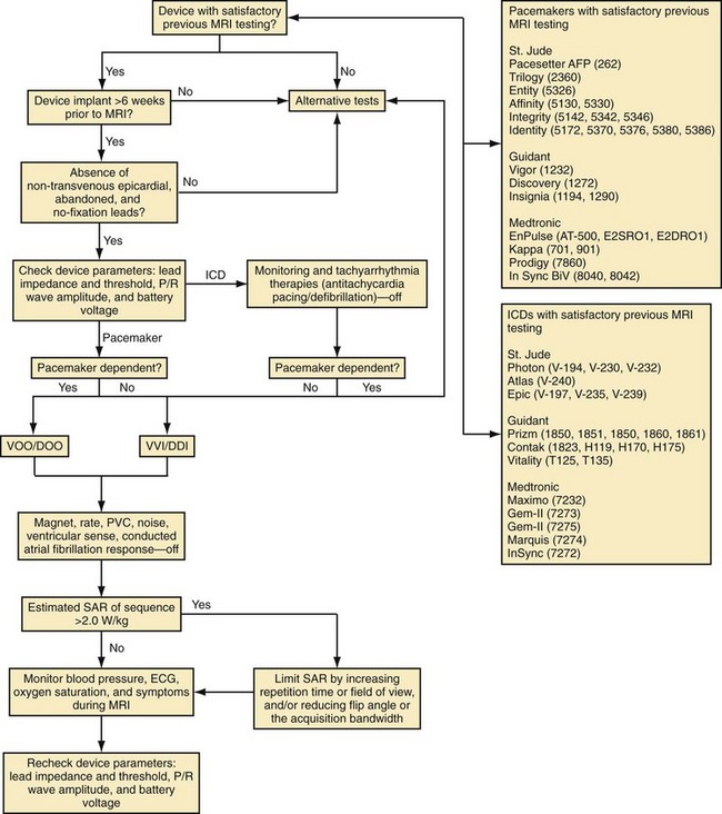
Based on in vitro and in vivo analyses,101 a protocol has been developed at the Johns Hopkins Hospital, including (1) device selection based on previous testing, (2) device programming to minimize inappropriate activation or inhibition of brady/tachyarrhythmia therapies, and (3) limitation of the SAR of MRI sequences (<2.0 W/kg).115 To perform MRI in patients with CIEDs, it was recommended that device generators prone to EMI be excluded (generally, older devices not on the tested devices list in the protocol, Fig. 33-6). Despite the low risk for lead and generator movement, patients were excluded who were judged to have higher risk of lead movement. Therefore, MRI was avoided in new CIED patients (<6 weeks) or patients with no fixation (superior vena cava coils) leads. Using the Hopkins Protocol, patients with mature active- and passive-fixation endocardial (and coronary sinus) leads of any diameter could safely undergo MR scans. MRI is avoided when device leads prone to heating are present, such as nontransvenous epicardial and abandoned (capped) leads.
To reduce the risk of inappropriate inhibition of pacing caused by detection of RF pulses, devices are programmed to an asynchronous, dedicated pacing mode in pacemaker-dependent patients. Also, given the lack of asynchronous pacing programming capability and transient loss of pacing capture after worst-case scenario (SAR 3.5 W/kg for 3 hours) with in vivo testing of 1 of 15 animals implanted with an ICD,101 we recommend excluding pacemaker-dependent patients with ICDs. To avoid inappropriate activation of pacing caused by tracking of RF pulses, we suggest device programming in patients without pacemaker dependence to a nontracking ventricular or dual-chamber inhibited pacing mode. We also recommend deactivation of rate response, premature ventricular contraction response, ventricular sense response, and conducted atrial fibrillation response to ensure that sensing of vibrations or RF pulses does not lead to unwarranted pacing. Although asynchronous pacing for short periods is typically well tolerated, we prefer to reduce the already-minimal chance of inducing arrhythmia or causing AV dyssynchrony by minimizing asynchronous pacing in patients without pacemaker dependence through deactivation of the magnet mode when possible. We typically deactivate tachyarrhythmia monitoring to avoid battery drainage that results from recording of multiple RF pulse sequences as arrhythmic episodes. Reed-switch activation in ICD systems disables tachyarrhythmia therapies. However, reed-switch function in the periphery versus the bore of the magnet is unpredictable; therefore, therapies should be disabled to avoid unwarranted antitachycardia pacing or shocks. Also, to reduce the risk of thermal injury and changes in lead threshold and impedance, we recommend limiting the estimated whole-body averaged SAR of MRI sequences (<2.0 W/kg when possible). Blood pressure, ECG, pulse oximetry, and symptoms should be monitored for the duration of the examination. We also favor the presence of a radiologist and cardiac electrophysiologist, or advanced cardiac life support–trained individual familiar with device programming and troubleshooting, during all scans.115 At the end of the examination, all device parameters are checked and programming restored to pre-MRI settings.
Using this protocol we have now safely performed MRI on more than 400 CIED patients. Our initial report of safety included 31 patients with permanent pacemakers (22% of whom were pacemaker dependent) and 24 patients with ICDs.115 No episodes of inappropriate inhibition or activation of pacing were observed, and there were no significant differences between baseline and immediate or long-term sensing amplitudes, lead impedances, or pacing thresholds. In this initial study, we successfully limited the system-estimated whole-body average SAR to 2.0 W/kg in more than 99% of sequences while maintaining the diagnostic capability of MRI. Almost all clinical experience has been obtained with 1.5-T magnets.
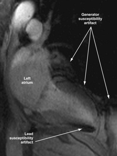
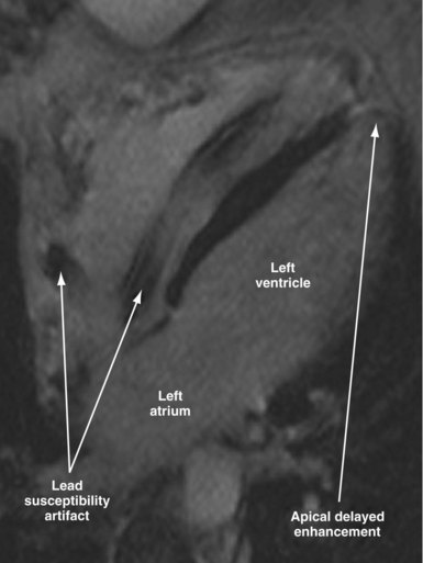
Susceptibility lead and generator artifacts are observed on MR images and are most pronounced on steady-state free-precession images (Fig. 33-7). Selecting imaging planes perpendicular to the plane of the device generator, shortening the echo time, and using spin-echo and fast spin-echo sequences reduces the qualitative extent of artifact. Bright artifact areas on delayed enhancement images can mimic areas of scar. However, areas with true late gadolinium enhancement can be identified by selection of appropriate image planes and correlation to functional images (Fig. 33-8). Diagnostic questions were answered in 100% of nonthoracic and 93% of thoracic studies. Clinical findings included diagnosis of vascular abnormalities (9 patients), diagnosis or staging of malignancy (9 patients), and assessment of cardiac viability before surgical ventricular reconstruction (13 patients).115
As long as manufacturers do not claim their devices to be “MR safe” or “MR compatible,” wide use of MRI in CIED patients is unlikely to be implemented.116 Future developments in lead and device design and technology may reduce MRI-induced heating and other forms of interference and make MRI safer.117,118 Shielding strategies include special coating (i.e., nanomagnetic) and low-pass filtering. A fiber-optic pacing lead (Biophan Technologies, Rochester, N.Y.) has been developed and appears safe in the MR environment.119 Most recently, a new pacemaker system (Medtronic EnRhythm MRI SureScan and CapSureFix MR leads) has been designed and tested for safe use in the MR environment. The new system includes hardware and software changes to ensure reliable operation during MRI and lead changes to reduce lead tip heating from RF energy. The EnRhythm MRI study, a prospective randomized controlled trial (RCT), was designed to test the safety of this new MRI-compatible pacing system.120 The results have favorable FDA review and suggest that a dual-chamber pacing system can be designed that is not affected by MR scanning.
Until fully MRI-compatible systems are clinically available, the decision to perform MRI in patients with potential contraindications is frequently made by considering the potential benefit of MRI relative to the attendant risks. The reader is encouraged to consult other resources, such as the recent American Heart Association Scientific Statement,121 and websites that provide more specific information regarding individual devices (e.g., www.mrisafety.com) for specific device testing details.
Neurostimulators
Case reports suggest that deep-brain stimulators (used to treat Parkinson’s disease and other movement disorders) are compatible with pacemakers or ICDs. Two scenarios are possible: the need to implant a cardiac device in a patient with a preexisting neurostimulator122–124 and the decision to implant neurostimulators in a CIED patient.125 Testing protocols and surgical approaches vary accordingly. If possible, testing for interactions should be performed preoperatively with a simulation screener device, intraoperatively, before discharge, and at each programming session. True bipolar sensing should be preferred. Unipolar deep-brain stimulation has not resulted in oversensing by pacemakers or ICDs.123–125 High-energy ICD shocks can reset neurostimulators to the off mode.124 The programmer wand for Medtronic neurostimulators contains a magnet that will close the reed switch of a pacemaker or ICD if moved close to the pocket. Transtelephonic monitoring (TTM) of the pacemaker may require that the neurostimulators be turned off transiently.125
Spinal cord stimulation has been used to treat peripheral vascular disease, intractable pain, and refractory angina pectoris. Concomitant use of pacemakers or ICDs and spinal cord stimulators is feasible, but testing is needed to avoid interactions.126,127 Oversensing of the output of a spinal cord stimulator programmed in a unipolar configuration can result in pacemaker inhibition or noise-reversion. Therefore, only bipolar spinal cord stimulation should be used. If a cardiac device is implanted after a spinal cord stimulator has been placed, bipolar sensing should be preferred. Ekre et al.128 reported on 18 consecutive patients treated with concomitant spinal cord stimulators for refractory angina and permanent pacemakers. Postimplantation testing consisted of ECG monitoring after programming of the pacemaker to a worst-case scenario (unipolar sensing and high sensitivity) while increasing the bipolar spinal cord stimulator output to the maximally tolerated level. There was no interference during acute testing. During long-term follow-up, there was no clinical evidence of pacemaker malfunction. No published experience is available on the concomitant use of CIEDs and other stimulators used to treat epilepsy (vagus nerve), fecal incontinence, or neurogenic bladder, but similar testing for interactions appears indicated. Stimulators in which the power source is not implanted but instead is RF-coupled (e.g., Medtronic Mattrix) are contraindicated in patients with pacemakers or ICDs.
Peripheral Nerve and Muscular Stimulation
Peripheral nerve stimulators are used to assess the extent of neuromuscular blockade intraoperatively or in the intensive care unit (ICU) and to locate nerves for blocks. Frequencies of less than 4 Hz (240 bpm) are unlikely to invoke noise-reversion modes. Reproducible inhibition of a unipolar right-sided VVI pacemaker during intraoperative left facial nerve stimulation with the standard train-of-four mode at 2 Hz has been reported.129 Peripheral nerve stimulators can inhibit the display of pacemaker pulses in modern digital monitors and make the diagnosis of EMI difficult.130 Diagnostic nerve conduction studies with needle electrodes introduced at or distal to elbows or knees are safe in pacemaker patients.131 Although guidelines suggest that electrodiagnostic studies are safe in patients with ICDs, provided special precautions are taken regarding the duration and frequency of stimulation pulses,132 experts recommend that tachyarrhythmia detection be turned off during such studies.133 This topic deserves further study.
Transcutaneous electrical nerve stimulation (TENS) and interferential electric current therapy are methods for the relief of acute and chronic musculoskeletal pain. A TENS unit consists of electrodes that are placed on the skin and connected to a generator that applies 20-µsec rectangular pulses of up to 60 mA at a frequency of 20 to 110 Hz. Output and frequency are adjusted to provide maximum pain relief. Early studies in patients with unipolar pacemakers reported inhibition by TENS, which at times could be eliminated by increasing the sensing threshold.134 In a study of the effects of TENS (at four sites, in 51 patients with 20 different pacemaker models), there were no instances of interference, inhibition, or reprogramming.135 It appears that TENS can be used safely in patients with modern implanted bipolar pacemakers and in patients with unipolar pacemakers if sensitivity is reduced. TENS electrodes should not be placed parallel to the lead vector; electrodes should be placed close to each other and as far as possible from the generator/lead system.
There is anecdotal experience with the use of TENS in patients with ICDs. Spurious shocks triggered by TENS application in patients with a variety of lead configurations and sensing algorithms have been documented.136–138 Ambulatory TENS has triggered ICD shocks in patients in whom acute provocative testing did not show interactions.139 Therefore, TENS should be avoided in patients with ICDs.
Chronic low-frequency stimulation of thigh muscles with biphasic symmetrical pulses of approximately 0.5 msec at frequencies of 15 to 63 Hz is useful in patients with chronic congestive heart failure and muscular weakness, many of whom have pacemakers or ICDs.140 In a pilot acute study, electrical stimulation of the neck and shoulder and of the thighs induced oversensing in three of eight patients with bipolar ICD systems.141 In select patients with pacemakers or ICDs in whom acute testing did not demonstrate interaction, long-term stimulation of thigh muscles with two different protocols was safe.142,143
Electroconvulsive Therapy
Electroconvulsive therapy (ECT) is useful in major depressive illness, especially in elderly and medically frail patients. Potential concerns are EMI from the ECT shock itself, oversensing of myopotentials during succinylcholine-induced fasciculations or from incomplete muscular paralysis during the induced seizure, and detection of the common but generally benign tachyarrhythmias that occur during the seizure. There are isolated case reports of uncomplicated ECT in patients with pacemakers. The Mayo Clinic has reported on ECT in 26 patients with pacemakers and three patients with ICDs, who received a total of 493 treatments.144 In patients with ICDs, tachyarrhythmia detection was disabled during the procedure. There were no instances of deleterious EMI. The authors concluded that ECT was safe in patients with implantable devices; they recommended a consultation and device interrogation before the beginning and at the end of treatment, as well as proper attention to grounding. No special programming appears to be necessary in patients with pacemakers. A nondepolarizing muscle relaxant can be used for patients who demonstrate oversensing of fasciculations. In patients with ICDs, tachyarrhythmia therapy should be disabled before the procedure and re-enabled as soon as the seizure is over.
Electrosurgery
Several electrosurgical techniques can generate EMI. The nomenclature of these techniques can be confusing. In Europe, “surgical diathermy” is often used to describe electrosurgical techniques, whereas in the United States, diathermy refers to the therapeutic application of current directly to the skin and is used for musculoskeletal ailments. Application of diathermy in heating or nonheating modes can result in excessive heating of tissue around leads and irreversible damage. RF (short-wave) or microwave diathermy is absolutely contraindicated in patients with pacemakers or ICDs.145
Although “electrocautery” is often used when referring to electrosurgery, in its strict sense, electrocautery describes a technique that promotes hemostasis by heating a metal instrument. Because no current is passed in the body, there is little or no risk of EMI. Battery-operated electrocautery is often used during pacemaker implantation. Electrofulguration and electrodessication are monoterminal techniques that destroy only superficial tissues; these are used mostly in dermatologic surgery. Because there is no dispersive ground electrode, minimal current is generated in the body away from the lesion being treated. The most common electrosurgery modalities, electrosection (electrocutting) and electrocoagulation, involve passing current through tissue. Coagulation or cutting current is usually delivered in monopolar configuration. Current begins at the active electrode located on the surgical instrument and, after traveling through the body, returns to the electrosurgical generator through a dispersing ground pad. Both cutting and coagulation use high-voltage, low-amperage current with high-frequency radio wave oscillations greater than 100,000 Hz. Pure cutting is generated by a continuous signal, rarely in excess of 2000 V. It creates high temperatures, causing cell explosion and evaporation. Coagulation is produced by a higher-amplitude signal (up to 10,000 V) that has a very short dwell time. The short, intermittent bursts produce heat within the tissue to control bleeding by thermally sealing the end of a blood vessel. Coagulation current is more likely than cutting current to cause interference.146 A blended current (e.g., 50% of the time on and 50% off) is used most frequently. Few surgeons use pure cutting current unless specifically asked.
In true bipolar electrocoagulation, the current flow is localized across the two poles of an instrument (e.g., coagulation forceps). Because current flow outside the surgical site is minimal and less power is used, it is unlikely to induce EMI. However, it is useful only for delicate surgical procedures and small vessels. Both monopolar and bipolar configurations are used during therapeutic endoscopic procedures (e.g., polypectomy, bleeding vessel cauterization).147 A recent study reported the prevalence of EMI during 52 gastrointestinal endoscopy procedures in 41 ICD patients, 10 of which required electrocautery. The ICD was programmed to monitor only for VT detection. No instances of EMI or tachycardia detection were noted, but the study has limited immediate clinical impact because of the small number of patients.148 Alternative surgical tools that will not produce EMI include the Shaw scalpel149 (Oximetrix, Mountain View, Calif.), laser scalpels,150,151 and ultrasound scalpels (Harmonic Scalpel, UltraCision, Smithfield, R.I.).152 Extensive in vitro testing of a microwave thermotherapeutic device for transurethral ablation of benign prostatic hyperplasia (BPH) suggests that it does not interact with pacemakers or ICDs.153
During electrosurgery in monopolar modes, the electric current spreads out and penetrates the entire body of the patient. This stray current may be interpreted by an implanted device as an intracardiac signal. Pacing inhibition, pacing triggering, automatic mode switching, noise reversion, or spurious tachyarrhythmia detection can occur,154 depending on the type of device, the programmed settings, the duration of EMI, and the channel in which the current is oversensed (Fig. 33-9; see also Fig. 33-2). Although some investigators have suggested that electrosurgery is safe in patients with activated ICDs,155 the risk of spurious tachyarrhythmia detection is clearly present. Electrosurgery can also induce sensor-mediated pacing at the upper rate limit in MV pacemakers.156 A more recent study was conducted in 92 patients with contemporary pacemaker or ICD who underwent electrocautery. The investigators identified only minor, temporary effects (brief atrial oversensing). Ventricular oversensing occurred rarely and only in pacemaker patients if electrocautery was less than 8 cm from the pulse generator. No ICD interactions were observed while VT detection was programmed on.157
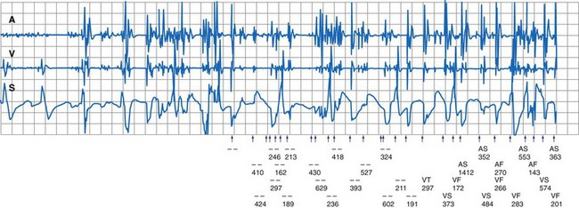
Figure 33-9 Spurious ventricular fibrillation detection due to electrosurgical equipment.
(From Pinski SL, Trohman RG: Interference in implanted devices. Part II. Pacing Clin Electrophsyiol 25:1496-1509, 2002.)
Other types of interaction are more common during electrosurgery than with other sources of EMI. In one study, up to 20% of older pacemakers reverted to the power-on reset mode, especially when the surgical wound was close to the pacemaker pocket.158 In a more recent, prospective study of 45 patients, electrosurgery triggered electrical reset in 7% of the patients.159 Myocardial electrical burns may occur if there is conductivity between the pacing electrode and the indifferent (return) electrode of the electrosurgical unit. This may be facilitated by a pacing electrode with a small surface area and a higher current density. Furthermore, protective circuitry (i.e., Zener diodes, thyristors) that shunt current away from the device may also contribute to the development of myocardial burns and subsequent elevation in pacing thresholds. Severe damage (and even VF) can occur if the dispersive electrode is disconnected from the circuit, because the pacing electrode becomes the return electrode in the circuit and delivers current to the heart directly.160 Irreversible generator failure caused by damage to internal circuitry can occur, especially when current is applied close to the device pocket. Permanent loss of output or runaway syndrome161 can be life threatening. Voltage control oscillator lockout has been identified as a mechanism of sudden output failure after electrosurgery current.162,163 Irreversible loss of output has been reported after an initial application of electrocoagulation current far away from the pacemaker system (i.e., during hip replacement).164 Although late recovery of function can occur,163 the device should not be trusted after initial failure.
Under special circumstances, an interaction may be documented between the self-check system of an electrosurgical generator and the high-voltage (HV) impedance test of Teligen ICD (Boston Scientific). Impedance of the patient return electrode patch in this particular electrosurgical generator model (Force FX, Valleylab, Boulder, Colo.) is constantly measured to ensure adequate skin contact and prevent skin injury during electrosurgical generator activation. Infused current is similar to that used for noninvasive testing of HV lead impedance in Teligen devices, and erroneous HV impedance measurements may occur. Other manufacturers (Medtronic and St. Jude were tested) use higher current for the same measurement and were immune to this form of interference.165
Guidelines exist for the management of CIED patients undergoing electrosurgery166,167 (Box 33-4). Short notice and scarcity of specialized personnel make compliance with such guidelines difficult, even in a large hospital with a well-staffed pacemaker clinic. Preoperative evaluation should routinely include a procedure for implantable device management in case electrocautery or other procedure is expected that may result in EMI. Ideally, the patient should be evaluated before surgery to determine pacemaker dependency and to document pacing and sensing thresholds, although chart review may suffice if the device was tested within 3 to 6 months in a chronic implant. Rate-response and tachyarrhythmia detection should be disabled just before surgery. In patients who are not pacemaker dependent, it is best not to change the programmed mode. Pacemaker-dependent patients should be reprogrammed to an asynchronous mode (DOO, VOO, AOO) above the intrinsic rate. Magnet application over the device may also be considered. In some pacemakers, magnet application does not result in asynchronous pacing, and in ICDs, magnet application suspends detection but does not trigger asynchronous pacing. Asynchronous pacing modes are not available in many ICDs. Current from the electrosurgical unit distorts the ECG, and it may be impossible to determine whether pacemaker inhibition occurs. Pulse oximeter plethysmography and invasive arterial pressure monitoring are invaluable in this situation. The dispersive pad should be placed as close as possible to the operating site and as far as possible from the pulse generator and leads, so that the electrical pathway is directed away from the pacing system. For example, during transurethral resection of the prostate, the grounding pad should be on the buttocks or lower leg. Good contact of the pad is mandatory, because with poor contact the pulse generator becomes the anode for the applied current. The patient’s body should not come in contact with any grounded electrical device that might provide an alternative pathway for current flow. Proper grounding of all electronic equipment used near the patient is essential.
Box 33-4
Management of CIED Patients Undergoing Electrosurgery
In the Operating Room
The monopolar probe should not be used within 15 cm of the pulse generator or lead. Cutting or coagulation time should be as short as possible, using the lowest feasible energy level. If electrosurgery causes inhibition of an implanted pacemaker, it should be used in short bursts so as to produce only short pauses at a time. If there is no underlying rhythm, current should be applied for less than 1 second at a time, followed by 5- to 10-second periods free from current to allow resumption of rhythm and normal hemodynamics. Communication with the OR personnel, including nurses, anesthesiologists, and surgeons, is very important. Ideally, a trained physician and the corresponding programmer should be available within the hospital whenever a CIED patient undergoes electrosurgery. Education, training, and certification of anesthesiologists in perioperative cardiac pacing appear necessary.168 Because damage to the pacing system may occur, the capability of instituting emergency pacing must be present. An external transcutaneous pulse generator and defibrillator should be available. In case of inadvertent reprogramming that is not hemodynamically tolerated, the pulse generator must be reprogrammed as soon as possible. Magnet application can be attempted as an interim measure (the magnet rate usually varies from 60 to 100 bpm) but is unlikely to help in these cases.
As more surgical procedures are performed outside the hospital (in physicians’ offices or freestanding ambulatory surgery centers), these recommendations become difficult to implement. Although industry-employed allied professionals often participate in the perioperative management of CIED patients in these settings, current guidelines suggest that they should perform technical support tasks only with an appropriately trained and experienced physician nearby (i.e., accessible to attend to the patient within a few minutes).169 It is not clear what precautionary practices are standard in the community. In a survey of 166 cutaneous surgeons performing electrosurgery of epitheliomas in the office setting, many had encountered instances of EMI with pacemakers or ICDs, but very few routinely checked or reprogrammed devices before or after surgery.170 Most of them restricted current bursts to less than 5 seconds, used minimal power, and avoided electrosurgery around a pacemaker or ICD. The estimated overall incidence of complications was low (0.8 cases per 100 years of surgical practice). The types of interference reported included pacemaker reprogramming, ICD firing, asystole, bradycardia, and premature pacemaker battery depletion. Use of bipolar forceps was not associated with interference.
More clinical evidence must be gathered on the incidence and severity of EMI with current implantable devices related to various electrosurgical techniques and operations. Current “blanket” recommendations may need to be revised to accommodate different degrees of risk and to allow efficient, cost-effective, high-quality perioperative management in the electrosurgical setting.167
Radiofrequency Identification Technology
Radiofrequency identification (RFID) systems have been extensively used in nonmedical environments, including retail stores for real-time tracking and highway toll systems for automatic pay. Unlike bar-code reader systems, RFID tags may be used to store larger amounts of data and allow better tracking. The technology has the potential to improve both the safety and the efficacy of care and utilization in hospital (and nonhospital) environments and will likely dramatically increase in the near future. The RFID tags are attached to the monitored entity, and stored data are read by a handheld or fixed device. RFID tags may be passive (powered by the reader) or active (powered by intrinsic power source). The FDA performed in vitro, worst-case scenario testing to identify interactions with pacemakers and ICDs when RFID readers were operated in close proximity. Pacemakers (15) and ICDs (15) were exposed to RFID readers at three frequency bands (134 kHz, 13.56 MHz, 915 MHz). Significant device interactions were present and were most common with modulated, low-frequency systems.171,172 To date, no clinical reports have described similar EMI.
Interference with Miscellaneous Medical Equipment
Left Ventricular Assist Devices
Left ventricular assist devices (LVADs) are being increasingly used for the treatment of refractory heart failure, and many candidates for this therapy have already received an ICD or pacemaker. Device interactions were reported with older-generation St. Jude ICDs (Atlas, Epic) and an LVAD (HeartMate II, Thoratec, Pleasanton, Calif.).173 These ICDs use 8-kHz communication frequency with the programmer wand. The HeartMate II uses a pulse-width modulator that operates at constant 7.2-kHz frequency and results in EMI that blocks proper wand communication of the affected ICD, while the ICD function otherwise remains normal. Although a cumbersome barrier method may be used to regain communication (large cast-iron pans placed over both devices for shielding),174 long-term management is optimized if the ICD generator is exchanged to an unaffected model. Newer models use different communication frequencies and appear to be immune to this problem.
Diagnostic Radiation
Diagnostic radiation has been thought to affect pacemakers or ICDs only rarely. More recent case reports suggest that EMI may occur during diagnostic computed tomography (CT) studies. This was confirmed in an in vitro study using the Irnich human body model.175 Five pacemaker/lead models (Thera SR, Kappa DR, EnRhythm, and Adapta by Medtronic; Synchrony II by St. Jude Medical) were tested in a CT scanner at maximum radiation level. Evidence of EMI was demonstrated by documentation of temporary pacing inhibition in all studied modern pacemakers, which are equipped with advanced CMOS circuits (all Medtronic models). EMI occurred when the CMOS was directly radiated. It was proposed that internal photoelectric effect from x-radiation affected the ECG amplifier and induced false sensing. The older pacemaker generator (Synchrony II) was not affected by radiation. These results cannot be extrapolated to other devices from the same or other manufacturers, but similar interactions should be expected.
Diagnostic radiation may affect the coating (polyvenylidene fluoride; PVDF or Kynar) of a pacemaker accelerator, as recently documented in a single-chamber, rate-modulated Zephyr pacemaker (St. Jude Medical) during cardiac catheterization.176 The PVDF surface is altered by movement but also by radiation, and a voltage is generated because of its piezoelectric properties, mimicking activity.177 Temporarily increased pacing rate may occur during cineangiography (Fig. 33-10).
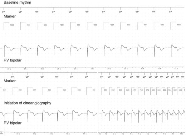
Video Capsule Endoscopy
The FDA and the device manufacturer consider the presence of a pacemaker or other CIED a contraindication to video capsule endoscopy. However, case reports and small series suggest that the procedure can be safe in such patients. Five pacemaker patients admitted to the hospital and continuously monitored during capsule endoscopy had no instances of interference with pacemaker function, and the quality of the images was good.178 Dubner et al.179 challenged 100 patients who had a variety of pacemakers with an external video capsule simulator transmitting at the same frequency. In four devices (2 St. Jude, 2 Biotronik), there was noise-reversion operation when the simulator capsule was positioned within 10 cm of the body, close to the generator. The interaction occurred within 10 seconds after capsule activation and was reproducible a week later. During clinical practice, the interaction is likely to occur only during the period when the capsule descends through the esophagus. The authors recommend that patients with pacemakers undergo initial testing with the external simulator to exclude significant EMI before undergoing the actual procedure with the video capsule system.
In an in vitro study, six ICD models from different manufacturers were exposed to the same external video capsule simulator, for a total of 864 test runs.180 There was consistent oversensing that resulted in false detection of VF in the Biotronik Belos ICD. Other devices (Medtronic GEM III, Guidant Vitality, St. Jude Profile) were affected neither during the in vitro tests nor in vivo in a limited number of patients. Until more information becomes available, it appears prudent to recommend that patients with CIEDs undergo capsule endoscopy only as inpatients and with tachyarrhythmia therapy disabled.
Direct-Current Cardioversion and Defibrillation
Direct-current (DC) external cardioversion and defibrillation with paddles (or disposable electrodes) can apply several thousand volts and tens of amperes of current to a CIED system. Of all sources of EMI, this represents the highest amount of energy delivered in the vicinity of such a device, and it has potential to damage the pulse generator as well as the myocardial tissue in contact with the lead or leads. At times, the backup (reset) mode is activated by the countershock. However, if the protection mechanism is overwhelmed by high-energy input, permanent pulse generator circuitry damage may ensue. Additionally, capacitative coupling or shunting in the pacemaker circuit may induce currents in pacemaker or defibrillator leads sufficient to cause thermal damage (burn) to the electrode-tissue interface, resulting in chronic threshold elevation. In dual-chamber pacemakers, cardioversion energy may be preferentially shunted to the ventricular lead.181 Even with modern pacemakers, acute exit block can occur. A mild, acute initial rise in capture threshold can be followed by exit block a few weeks later.182
The risk of damage to the implanted device depends on the amount of energy applied, the characteristics of the device and lead, and the distance between the paddles or pads and the pulse generator and leads. Box 33-5 lists recommendations for external cardioversion in patients with CIEDs. In elective situations, the minimum energy that is likely to be successful should be delivered. External cardioversion or defibrillation with a biphasic waveform is more efficient (i.e., requires less energy) than the conventional damped sine-wave monophasic shocks and should be preferred in patients with implanted devices. Unipolar pacing systems are more susceptible to damage than bipolar systems. Whenever possible, an anteroposterior configuration of the shocking electrodes should be employed, because it maximizes the distance between the source and the implanted generator. If an anteroapical position must be used, the electrodes should be at least 10 cm from the pulse generator. However, this may be impossible with devices implanted in a right pectoral pocket, because the anterior paddle will lie directly on top of it. Transient elevations in capture threshold are common after DC shocks and should be anticipated. The threshold rise is usually temporary, lasting up to a few minutes, but occasionally the threshold remains elevated permanently and necessitate lead replacement. Preprocedural and postprocedural interrogation and device testing for proper function should follow external DC shocks to all implantable devices.
Box 33-5
Management of CIED Patients Undergoing External Cardioversion or Defibrillation
Internal cardioversion may be attempted in patients who fail external cardioversion of atrial fibrillation (AF). There is limited published experience with this procedure in patients with pacemakers. There were no instances of pacemaker malfunction in seven patients who underwent internal cardioversion of AF, with electrodes in the right atrium and in the coronary sinus or left pulmonary artery, with biphasic shocks of up to 20 J.183 However, when high-energy endocavitary shocks were used for ablation purposes, pacemaker failure was common.184
Radiofrequency Ablation
Radiofrequency current, delivered as an unmodulated sine wave at 500 to 1000 kHz, can interact unpredictably with CIEDs. Energy delivery may result in asynchronous pacing, rapid tracking, spurious tachyarrhythmia detection, and electrical reset. Different interactions may be seen (in the same patient) during consecutive energy applications. Interactions are generally transient and terminate with cessation of energy delivery. In vitro and in vivo studies have examined the incidence, mechanisms, and risk factors for these interactions. Dick et al.185 investigated the effects of RF current (55 W; tip temperature 65°-70° C) applied to four different pacing or defibrillation leads in a tissue bath model. Photographic and microscopic examination after energy delivery revealed no damage to the target lead. No malfunction occurred in the attached pulse generators. The magnitude of induced current measured at the target tip lead was inversely proportional to the distance. Significant current was detected only when the ablation catheter was less than 1 cm from the target lead tip. Chin et al.186 studied 19 pulse generators implanted in 12 dogs and found that interactions depended on the proximity of current application to the pacing leads. Interactions were common at 1 cm and absent at more than 4 cm. The most dangerous interaction was runaway pacing with possible VF induction.
The clinical incidence of acute interaction between RF current application and permanent pacemakers has ranged widely. The incidence and severity of EMI depend in part on the protective circuits of the implanted device.187 The combined incidence of acute pacemaker malfunction during RF current application in three relatively large series involving a total of 125 patients with assorted pacemakers was 44%.188,189 The most common interaction was asynchronous pacing caused by noise reversion, followed by oversensing resulting in refractory period extension and “functional undersensing,” pacemaker inhibition, or antitachycardia pacing in special pacemakers. Electrical reset, RF-induced pacemaker tachycardia, erratic behavior, and transient loss of capture were less common. In contrast, Proclemer et al.190 did not observe transient or permanent pacemaker dysfunction in 70 consecutive patients with Medtronic Thera and Kappa single- and dual-chamber pacemakers with unipolar leads who underwent AV junction RFA. The pacemakers were implanted before RFA in a single-session procedure and were transiently programmed to VVI mode at 30 bpm.
The long-term effects of RF application on permanent pacing systems have been less well studied. Exit block (possibly caused by scar at the lead-tissue interface), lead damage, and chronic generator malfunction (requiring replacement) have been reported.187,189,191 In two series of patients with pacemakers, changes in lead impedance and pacing and sensing thresholds did not appear clinically significant.187,190 In a study of 59 patients with preexisting pacemaker (46) or defibrillator leads (13) undergoing AV junction RFA, a significant increase in pacing threshold was present immediately after ablation and further increased 24 hours later.192 A twofold increase in pacing threshold was much more likely to occur in patients with defibrillator leads. Two of the ICD patients (15%) and two of the pacemaker patients (4%) had a progressive rise in pacing threshold requiring lead revision. The mechanism of the increased vulnerability of the ICD leads was not clear.
A few simple precautions can minimize adverse outcomes with RFA. Complete pacemaker inhibition is dangerous in patients who are without an escape rhythm during AV junction RFA. Rate responsiveness should be disabled. Pacing at the upper rate limit may occur when MV pacemakers that measure transthoracic impedance misinterpret RF current.193 Tachyarrhythmia detection should be disabled in patients with ICDs to prevent spurious therapies. Older pacemakers should not be trusted to provide backup pacing, because loss of output or capture could occur despite programming an asynchronous mode. Pacemakers and ICDs should be checked carefully after RF catheter ablation.
Also, RF energy can be used for ablation of other tissues. Uneventful percutaneous RF trigeminal rhizotomy194 and intrahepatic RFA of liver neoplasms195 in patients with pacemakers have been reported. With extracardiac RFA, the current return pad should be placed as close as possible to the delivery electrodes.196
Lithotripsy
Acoustic radiation, from extracorporeal shock wave lithotripsy (ESWL) machines, provides a noninvasive means to disintegrate renal, ureteral, gallbladder, and biliary calculi. With the original device (Dornier HM3, Dornier Medical System, Marietta, Ga.), the patient lies in a water bath and multiple (~1500) hydraulic shocks are generated from an underwater 20-kV spark gap and focused on the calculi by an ellipsoid metal reflector. The shock wave can produce ventricular extrasystoles, so it is synchronized to the R wave. Implanted devices could be subject to electrical interference from the spark gap and mechanical damage from the hydraulic shock wave. Newer units (e.g., Dornier Compact Delta) use an enclosed water cushion for shock wave coupling. Other units use electromagnetic (e.g., Lithostar, Siemens Medical Systems, Iselin, N.J.) or piezoelectric (e.g., Wolf Piezolith, Richard Eolf GmbH, Knittlingen, Gemany) shock wave generators.197 Most information regarding interactions with CIEDs has been collected with the Dornier HM3 unit.
Several investigators have studied the effects of ESWL on pacemakers in vitro.198–200 Pacemaker output was not inhibited by properly synchronous shocks, but asynchronous shocks caused inhibition in both unipolar and bipolar devices. During AV sequential pacing, a shock inappropriately synchronized to the atrial pacing pulse was often sensed by the ventricular channel, with the potential to cause inhibition of the ventricular output. Intermittent reversion to magnet mode can occur because of transient closure of the reed switch from the high-energy vibration. Other responses noted during in vitro testing included an increase in pacing rate secondary to tracking of EMI in the atrial channel, noise reversion, spurious tachyarrhythmia detection,201 and malfunction of the reed switch. Activity-sensing pacemakers increased their pacing rate to the upper limit within 1 minute after the shock. ESWL caused no physical damage to the hermetic seal or internal components of the pacemakers tested, except that piezoelectric crystals shattered when an activity-sensing pacemaker was placed at the focal point of the ESWL.198 In vitro testing of two ICDs with a new-generation lithotripter did not disclose any adverse interactions (even with generator placed within focus of lithotripter), provided that the shock waves were applied synchronized to the R wave.196
Case reports and clinical series suggest that ESWL is safe to use with CIEDs as long as the device and target are at least 6 cm apart. Adverse events have been rare and mild, occurring mostly with older devices.202–205 Activity-sensing rate-adaptive devices implanted in the thorax can undergo lithotripsy safely, but the procedure should be avoided if the device is located in the abdomen. Synchronization of the shocks to the R wave is crucial. Activity sensors and tachyarrhythmia detection should be temporarily disabled in all cases. Reprogramming of dual-chamber pacemakers to VVI or VOO (if the patient is pacemaker dependent) avoids ventricular inhibition caused by shocks synchronized to the atrial output, irregular pacing rate, tracking of induced supraventricular tachycardia, and triggering of the ventricular output by EMI. Careful follow-up should be performed over the next several months to ensure appropriate function of the reed switch. The piezoelectric shock wave generator does not induce ventricular extrasystoles, and therefore synchronization to the QRS complex is not required. This unit appears especially safe to use in CIED patients.
Dental Equipment
Multiple potential sources of EMI are present in the dental office, including sonic and ultrasonic scalers, amalgamators, composite light curing units, x-ray units and view boxes, dental chairs and lights, electronic apex locators, and ultrasonic bath cleaners. Research in this area has been of suboptimal quality. The paucity of reports of severe interactions between modern CIEDs and dental equipment suggests that this is not a clinical problem. Magnetic fields in the dental office are not strong enough to close the reed switch.206 Earlier reports described pacemaker EMI with magnetorestrictive ultrasonic scalers, but not with piezoelectric ultrasonic scalers.207 An in vitro study reported pacemaker inhibition by magnetorestrictive ultrasonic scalers up to distances of 37.5 cm.9 However, review of the published telemetry strips suggests that these were not instances of true pacemaker inhibition, but instead represented interference with the telemetry link. Until further tests are conducted, it is prudent to avoid magnetorestrictive ultrasonic scalers in CIED patients.207 Manufacturers of electronic apex locators warn against the use of these devices in patients with pacemakers. In bench testing, four of five electronic apex locators did not interfere with a Biotronik pacemaker.208 Safe use of an electronic apex locator in a patient with a pacemaker has been reported.209 Prosthetic dental minimagnets can activate the reed switch only if placed very close (1 cm) to the pacemaker and therefore do not represent a risk to patients with a pacemaker.210
Radiotherapy
Radiotherapy can induce various responses in implanted devices. EMI produced by the radiotherapy machine can result in pacing inhibition, tracking, noise reversion, or inappropriate ICD discharges. Most important is the risk of permanent generator damage caused by ionizing radiation.211 Current devices incorporating CMOS technology may incur damage during radiation therapy. Ionizing therapeutic radiation acts on the silicone and silicone oxide insulators within the semiconductors. Two potential mechanisms of damage have been described.
Cumulative radiation can result in damage to circuit components, altering transistor parameters or creating electrical shorts that result in premature battery depletion. Failure may manifest as changes in sensitivity, amplitude, or pulse width; loss of telemetry; output failure; or runaway rates. This is uncommon unless the device is directly irradiated. More difficult to predict and avoid is random damage to the device’s memory caused by scatter radiation.212 Modern pacemakers and ICDs include memory error detection and correction schemes in their software programs. As a normal part of daily self-diagnostics, devices locate and correct affected memory locations. However, if the degree of memory alteration is beyond the capability of self-correcting algorithms, the device may invoke a ROM-based operating mode, referred to as “safety mode.” This ensures that the patient is protected with basic pacing and shock therapy. Physicians should be advised of this possibility and should carefully monitor device operation during and after radiation therapy.
Previously, a total absorbed dose of up to 2 Gy was considered safe in permanent pacemakers.211 Later studies suggested that pacemaker susceptibility to radiotherapy is highly variable and that severe malfunction can occur at even lower doses. Mouton et al.213 irradiated 96 pacemakers in vitro with a high-energy photon beam. One pacemaker had severe malfunction at a cumulative dose of 0.15 Gy; at 2 Gy, 6% of pacemakers developed severe malfunction. The dose rate also affected the likelihood of failure, and the authors recommended using dose rates lower than the standard of 2 Gy/min. Hurkmans et al.214 performed in vitro testing during which 7 of 19 current pacemakers lost output at 120 Gy. Eight pacemakers showed inhibition during irradiation in the direct beam, whereas five pacemakers showed no malfunction. They also evaluated the effect of radiotherapy on ICDs. In their study, 11 modern ICDs were irradiated with a 6-megavolt photon beam with a cumulative dose of 120 Gy. Electromagnetic noise caused inappropriate sensing in all ICDs and would have resulted in inappropriate shocks in four devices. At the end of the 4- to 5-day consecutive irradiation schedule planned in the study, all devices had failed. The majority of the ICDs reached complete loss of function at dose levels between 0.5 and 1.5 Gy.215 Kapa et al.216 studied the effects of scatter radiation on ICD and cardiac resynchronization therapy (CRT) devices. The authors exposed 12 ICD and 8 CRT-ICDs to 400 cGy of scatter radiation from a 6-MV photon beam. No evidence of reset or malfunction was noted during or after radiation. The authors also performed a retrospective review of 12 patients with ICDs undergoing radiotherapy at their institution. The device was outside the radiation field in all cases. No episodes of device reset, inappropriate sensing or therapy, or changes in programmed parameters were found in any of the 12 patients.
Radiation oncology centers should have protocols for patients with implantable antiarrhythmic devices,217 but a recent survey reveals wide variations among facilities regarding patient management precautions.218 Manufacturers offer widely differing guidelines for patient management during radiotherapy, reflecting discrepancies in the perceived mechanism of damage. Vendors agree that the pulse generator should not be situated directly within the radiation field. If that is the case, the generator should be removed and reimplanted away from the field. Manufacturers also vary as to the total radiation exposure to the generator that should be allowed. For example, Medtronic recommends a limitation of 5 Gy or less for its pacemakers and 1 Gy or less to 5 Gy or less for its ICDs, depending on the model. In contrast, St. Jude Medical recommends a maximal cumulative dose to its pacemakers of 20 to 30 Gy. Boston Scientific offers no guidelines regarding dose limitation, emphasizing the random nature of memory damage by radiation scatter. Boston Scientific recommends maximizing shielding at the machine head but specifically discourages placing a lead apron over the pulse generator during treatment, because of its potential for increasing scatter. In contrast, St. Jude Medical and Sorin recommend shielding of the pacemaker with a piece of lead apron. The manufacturers also differ in their recommendations regarding the extent and frequency of patient monitoring during and after radiotherapy.
It is difficult to provide universal guidelines for the management of patients with pacemakers or ICDs who are undergoing radiotherapy. The mode and site of radiation therapy, as well as the clinical characteristics of the patient (presence of pacemaker or ICD, pacemaker dependency) need to be considered.217 Monitoring should be tailored according to risk with device failure. In high-risk cases, device interrogation after each session may be required. In other cases, weekly evaluation may be appropriate.167 Box 33-6 proposes streamlined precautions to consider before, during, and after radiotherapy in patients with cardiac implantable electronic devices.
Box 33-6
Management of CIED Patients Undergoing Radiotherapy
During Treatments
1 American National Standards Institute, Association for the Advancement of Medical Instrumentation. Active implantable medical devices: electromagnetic compatibility. EMC test protocols for implantable cardiac pacemakers and implantable cardioverter-defibrillators. ANSI/AAMI PC69:2007. Washington, DC: ANSI. 2007.
2 . Radiofrequency wireless technology in medical devices. Accessed January 2011 http://www.fda.gov/MedicalDevices/DeviceRegulationandGuidance/GuidanceDocuments/ucm077210.htm
3 Barbaro V, Bartolini P, Calcagnini G, et al. On the mechanisms of interference between mobile phones and pacemakers: parasitic demodulation of GSM signal by the sensing amplifier. Phys Med Biol. 2003;48:1661-1671.
4 Matthews JC, Betley D, Morady F, et al. Adverse interaction between a left ventricular assist device and an implantable cardioverter-defibrillator. J Cardiovasc Electrophysiol. 2007;18:1107-1108.
5 Center for Devices and Radiological Health. Medical Device Reporting. US Food and Drug Administration. http://www.accessdata.fda.gov/scripts/cdrh/cfdocs/cfMAUDE/search.CFM.
6 Angeloni A, Barbaro V, Bartolini P, et al. A novel heart/trunk simulator for the study of electromagnetic interference with active implantable devices. Med Biol Eng Comput. 2003;41:550-555.
7 Dawson TW, Stuchly MA, Caputa K, et al. Pacemaker interference and low-frequency electric induction in humans by external fields and electrodes. IEEE Trans Biomed Eng. 2000;47:1211-1218.
8 Grant FH, Schlegel RE. Effects of an increased air gap on the in vitro interaction of wireless phones with cardiac pacemakers. Bioelectromagnetics. 2000;21:485-490.
9 Miller CS, Leonelli FM, Latham E. Selective interference with pacemaker activity by electrical dental devices. Oral Surg Oral Med Oral Pathol Oral Radiol Endod. 1998;85:33-36.
10 CENELEC. Active implantable medical devices. Part 2-1. Particular requirements for active implantable medical devices intended to treat bradyarrhythmia (cardiac pacemakers). Bruxelles: Comité Européen de Normalisation Electrotechnique. 2003.
11 CENELEC. Active implantable medical devices. Part 2-2. Particular requirements for active implantable medical devices intended to treat tachyarrhythmia (includes implantable defibrillators). Bruxelles: Comité Européen de Normalisation Electrotechnique. 2006.
12 Southorn PA, Kamath GS, Vasdev GM, et al. Monitoring equipment induced tachycardia in patients with minute ventilation rate-responsive pacemakers. Br J Anaesth. 2000;84:508-509.
13 Chew EW, Troughear RH, Kuchar DL, et al. Inappropriate rate change in minute ventilation rate responsive pacemakers due to interference by cardiac monitors. Pacing Clin Electrophysiol. 1997;20:276-282.
14 Khunnawat C, Mukerji S, Sankaran S, et al. Echocardiography induced tachycardia in a patient with a minute ventilation rate responsive pacemaker. J Interv Card Electrophysiol. 2005;14:51-53.
15 McIvor ME, Reddinger J, Floden E, et al. Study of Pacemaker and Implantable Cardioverter Defibrillator Triggering by Electronic Article Surveillance Devices (SPICED TEAS). Pacing Clin Electrophysiol. 1998;21:1847-1861.
16 Hayes DL, Holmes DRJr, Gray JE. Effect of 1.5 tesla nuclear magnetic resonance imaging scanner on implanted permanent pacemakers. J Am Coll Cardiol. 1987;10:782-786.
17 Fontaine JM, Mohamed FB, Gottlieb C, et al. Rapid ventricular pacing in a pacemaker patient undergoing magnetic resonance imaging. Pacing Clin Electrophysiol. 1998;21:1336-1339.
18 Kolb C, Zrenner B, Schmitt C. Incidence of electromagnetic interference in implantable cardioverter defibrillators. Pacing Clin Electrophysiol. 2001;24:465-468.
19 Gunderson BD, Gillberg JM, Swerdlow CD. Importance of oversensing in inappropriate detection of ventricular fibrillation by chronically implanted ICDs. Heart Rhythm. 2005;1:S244.
20 Butrous GS, Male JC, Webber RS, et al. The effect of power frequency high intensity electric fields on implanted cardiac pacemakers. Pacing Clin Electrophysiol. 1983;6:1282-1292.
21 Saeed M, Link MS, Mahapatra S, et al. Analysis of intracardiac electrograms showing monomorphic ventricular tachycardia in patients with implantable cardioverter-defibrillators. Am J Cardiol. 2000;85:580-587.
22 Schmitt C, Brachmann J, Waldecker B, et al. Implantable cardioverter-defibrillator: possible hazards of electromagnetic interference. Pacing Clin Electrophysiol. 1991;14:982-984.
23 Ferrick KJ, Johnston D, Kim SG, et al. Inadvertent AICD inactivation while playing bingo. Am Heart J. 1991;121:206-207.
24 Rasmussen MJ, Friedman PA, Hammill SC, et al. Unintentional deactivation of implantable cardioverter-defibrillators in health care settings. Mayo Clin Proc. 2002;77:855-859.
25 Kolb C, Deisenhofer I, Weyerbrock S, et al. Incidence of antitachycardia therapy suspension due to magnet reversion in implantable cardioverter-defibrillators. Pacing Clin Electrophysiol. 2004;27:221-223.
26 Levine PA, Moran MJ. Device eccentricity: postmagnet behavior of DDDR pacemakers with automatic threshold tracking. Pacing Clin Electrophysiol. 2000;23:1570-1572.
27 Laudon MK. Pulse output: design of cardiac pacemakers. New York: IEEE Press; 1995. pp 251-276
28 Schoenfeld MH, Compton SJ, Mead RH, et al. Remote monitoring of implantable cardioverter defibrillators: a prospective analysis. Pacing Clin Electrophysiol. 2004;27:757-763.
29 Jung W, Rillig A, Birkemeyer R, et al. Advances in remote monitoring of implantable pacemakers, cardioverter-defibrillators and cardiac resynchronization therapy systems. J Interv Card Electrophysiol. 2008;23:73-85.
30 Toivonen L, Valjus J, Hongisto M, et al. The influence of elevated 50 Hz electric and magnetic fields on implanted cardiac pacemakers: the role of the lead configuration and programming of the sensitivity. Pacing Clin Electrophysiol. 1991;14:2114-2122.
31 Hayes DL, Carrillo RG, Findlay GK, et al. State of the science: pacemaker and defibrillator interference from wireless communication devices. Pacing Clin Electrophysiol. 1996;19:1419-1430.
32 Yesil M, Bayata S, Postaci N, et al. Pacemaker inhibition and asystole in a pacemaker dependent patient. Pacing Clin Electrophysiol. 1995;18:1963.
33 Ruggera PS, Witters DM, Bassen HI. In vitro testing of pacemakers for digital cellular phone electromagnetic interference. Biomed Instrum Technol. 1997;31:358-371.
34 Bassen HI, Moore HJ, Ruggera PS. Cellular phone interference testing of implantable cardiac defibrillators in vitro. Pacing Clin Electrophysiol. 1998;21:1709-1715.
35 Tan KS, Hinberg I. Can wireless communication systems affect implantable cardiac pacemakers? An in vitro laboratory study. Biomed Instrum Technol. 1998;32:18-24.
36 Schlegel RE, Grant FH, Raman S, et al. Electromagnetic compatibility study of the in-vitro interaction of wireless phones with cardiac pacemakers. Biomed Instrum Technol. 1998;32:645-655.
37 University of Oklahoma Wireless EMC Center. In vitro study of the interaction of wireless phones and implantable cardioverter-defibrillators. Accessed December 2010 http://www.ou.edu/engineering/emc/Side/Achievments/Research%20Projects/ICDs.dwt
38 Hayes DL, Wang PJ, Reynolds DW, et al. Interference with cardiac pacemakers by cellular telephones. N Engl J Med. 1997;336:1473-1479.
39 Naegeli B, Osswald S, Deola M, et al. Intermittent pacemaker dysfunction caused by digital mobile telephones. J Am Coll Cardiol. 1996;27:1471-1477.
40 Hekmat K, Salemink B, Lauterbach G, et al. Interference by cellular phones with permanent implanted pacemakers: an update. Europace. 2004;6:363-369.
41 Trigano A, Blandeau O, Dale C, et al. Reliability of electromagnetic filters of cardiac pacemakers tested by cellular telephone ringing. Heart Rhythm. 2005;2:837-841.
42 Sparks PB, Mond HG, Joyner KH, et al. The safety of digital mobile cellular telephones with minute ventilation rate adaptive pacemakers. Pacing Clin Electrophysiol. 1996;19:1451-1455.
43 Nowak B, Rosocha S, Zellerhoff C, et al. Is there a risk for interaction between mobile phones and single lead VDD pacemakers? Pacing Clin Electrophysiol. 1996;19:1447-1450.
44 Elshershari H, Celiker A, Ozer S, et al. Influence of D-net (EUROPEAN GSM-standard) cellular telephones on implanted pacemakers in children. Pacing Clin Electrophysiol. 2002;25:1328-1330.
45 Chiladakis JA, Davlouros P, Agelopoulos G, et al. In-vivo testing of digital cellular telephones in patients with implantable cardioverter-defibrillators. Eur Heart J. 2001;22:1337-1342.
46 Fetter JG, Ivans V, Benditt DG, et al. Digital cellular telephone interaction with implantable cardioverter-defibrillators. J Am Coll Cardiol. 1998;31:623-628.
47 Occhetta E, Plebani L, Bortnik M, et al. Implantable cardioverter-defibrillators and cellular telephones: is there any interference? Pacing Clin Electrophysiol. 1999;22:983-989.
48 Calcagnini G, Censi F, Floris M, et al. Evaluation of electromagnetic interference of GSM mobile phones with pacemakers featuring remote monitoring functions. Pacing Clin Electrophysiol. 2006;29:380-385.
49 Chiu CC, Huh J, De Souza L, et al. A prospective pediatric clinical trial of digital music players: do they interfere with pacemakers? J Cardiovasc Electrophysiol. 2009;20:44-49.
50 Bassen H. Low frequency magnetic emissions and resulting induced voltages in a pacemaker by iPod portable music players. Biomed Eng Online. 2008;7:7.
51 Thaker JP, Patel MB, Jongnarangsin K, et al. Electromagnetic interference with pacemakers caused by portable media players. Heart Rhythm. 2008;5:538-544.
52 Webster G, Jordao L, Martuscello M, et al. Digital music players cause interference with interrogation telemetry for pacemakers and implantable cardioverter-defibrillators without affecting device function. Heart Rhythm. 2008;5:545-550.
53 Lee S, Fu K, Kohno T, et al. Clinically significant magnetic interference of implanted cardiac devices by portable headphones. Heart Rhythm. 2009;6:1432-1436.
54 Sakakibara Y, Mitsui T. Concerns about sources of electromagnetic interference in patients with pacemakers. Jpn Heart J. 1999;40:737-743.
55 De Cock CC, Spruijt HJ, van Campen LM, et al. Electromagnetic interference of an implantable loop recorder by commonly encountered electronic devices. Pacing Clin Electrophysiol. 2000;23:1516-1518.
56 Thaker JP, Patel MB, Jongnarangsin K, et al. Electromagnetic interference in an implantable loop recorder caused by a portable digital media player. Pacing Clin Electrophysiol. 2008;31:1345-1347.
57 Tri JL, Trusty JM, Hayes DL. Potential for personal digital assistant interference with implantable cardiac devices. Mayo Clin Proc. 2004;79:1527-1530.
58 Santucci PA, Haw J, Trohman RG, et al. Interference with an implantable defibrillator by an electronic antitheft-surveillance device. N Engl J Med. 1998;339:1371-1374.
59 Tan KS, Hinberg I. Can electronic article surveillance systems affect implantable cardiac pacemakers and defibrillators? [abstract]. Pacing Clin Electrophysiol. 1998;21:960.
60 Mugica J, Henry L, Podeur H. Study of interactions between permanent pacemakers and electronic antitheft surveillance systems. Pacing Clin Electrophysiol. 2000;23:333-337.
61 Groh WJ, Boschee SA, Engelstein ED, et al. Interactions between electronic article surveillance systems and implantable cardioverter-defibrillators. Circulation. 1999;100:387-392.
62 US Food and Drug Administration, Center for Devices and Radiological Health. Guidance on labeling for electronic anti-theft systems. Accessed December 2010 http://www.fda.gov/downloads/MedicalDevices/DeviceRegulationandGuidance/GuidanceDocuments/UCM070913.pdf
63 Moss CE. Exposures to electromagnetic fields while operating walk-through and hand-held metal detectors. Appl Occup Environ Hyg. 1998;13:501-504.
64 Kolb C, Schmieder S, Lehmann G, et al. Do airport metal detectors interfere with implantable pacemakers or cardioverter-defibrillators? J Am Coll Cardiol. 2003;41:2054-2059.
65 Burlington DB. Important information on anti-theft and metal detector systems and pacemakers, ICDs, and spinal cord stimulators. Accessed January 2011 http://www.fda.gov/MedicalDevices/Safety/AlertsandNotices/PublicHealthNotifications/ucm062288.htm
66 Dawson TW, Caputa K, Stuchly MA, et al. Pacemaker interference by magnetic fields at power line frequencies. IEEE Trans Biomed Eng. 2002;49:254-262.
67 Trigano A, Blandeau O, Souques M, et al. Clinical study of interference with cardiac pacemakers by a magnetic field at power line frequencies. J Am Coll Cardiol. 2005;45:896-900.
68 Chan NY, Wai-Ling Ho L. Inappropriate implantable cardioverter-defibrillator shock due to external alternating current leak: report of two cases. Europace. 2005;7:193-196.
69 Paraskevaidis S, Polymeropoulos KP, Louridas G. Inappropriate ICD therapy due to electrical interference: external alternating current leakage. J Invasive Cardiol. 2004;16:339.
70 Sabate X, Moure C, Nicolas J, et al. Washing machine associated 50 Hz detected as ventricular fibrillation by an implanted cardioverter defibrillator. Pacing Clin Electrophysiol. 2001;24:1281-1283.
71 Madrid A, Sanchez A, Bosch E, et al. Dysfunction of implantable defibrillators caused by slot machines. Pacing Clin Electrophysiol. 1997;20:212-214.
72 Pinski SL, Trohman RG. Interference in implanted cardiac devices. Part I. Pacing Clin Electrophysiol. 2002;25:1367-1381.
73 Manolis AG, Katsivas AG, Vassilopoulos CV, et al. Implantable cardioverter-defibrillator-an unusual case of inappropriate discharge during showering. J Interv Card Electrophysiol. 2000;4:265-268.
74 Lee SW, Moak JP, Lewis B. Inadvertent detection of 60-Hz alternating current by an implantable cardioverter defibrillator. Pacing Clin Electrophysiol. 2002;25:518-519.
75 Rickli H, Facchini M, Brunner H, et al. Induction ovens and electromagnetic interference: what is the risk for patients with implanted pacemakers? Pacing Clin Electrophysiol. 2003;26:1494-1497.
76 Binggeli C, Rickli H, Ammann P, et al. Induction ovens and electromagnetic interference: what is the risk for patients with implantable cardioverter defibrillators? J Cardiovasc Electrophysiol. 2005;16:399-401.
77 Seifert T, Block M, Borggrefe M, et al. Erroneous discharge of an implantable cardioverter defibrillator caused by an electric razor. Pacing Clin Electrophysiol. 1995;18:1592-1594.
78 Garg A, Wadhwa M, Brown K, et al. Inappropriate implantable cardioverter defibrillator discharge from sensing of external alternating current leak. J Interv Card Electrophysiol. 2002;7:181-184.
79 Haegeli LM, Sterns LD, Adam DC, et al. Effect of a Taser shot to the chest of a patient with an implantable defibrillator. Heart Rhythm. 2006;3:339-341.
80 Lakkireddy D, Khasnis A, Antenacci J, et al. Do electrical stun guns (Taser-X26) affect the functional integrity of implantable pacemakers and defibrillators? Europace. 2007;9:551-556.
81 Van Lake P, Mattioni T. The effect of therapeutic magnets on implantable pacemaker and defibrillator devices [abstract]. Pacing Clin Electrophysiol. 2000;23:723.
82 Wayar L, Mont L, Silva RM, et al. Electrical interference from an abdominal muscle stimulator unit on an implantable cardioverter-defibrillator: report of two consecutive cases. Pacing Clin Electrophysiol. 2003;26:1292-1293.
83 Lau EW, Birnie DH, Lemery R, et al. Acupuncture triggering inappropriate ICD shocks. Europace. 2005;7:85-86.
84 Furrer M, Naegeli B, Bertel O. Hazards of an alternative medicine device in a patient with a pacemaker. N Engl J Med. 2004;350:1688-1690.
85 Cartwright CE, Breysse PN, Boother L. Magnetic field exposures in a petroleum refinery. Appl Occup Environ Hyg. 1993;8:587-592.
86 De Rotte AA, Van Der Kemp P. Electromagnetic interference in pacemakers in single-engine fixed-wing aircraft: a European perspective. Aviat Space Environ Med. 2002;73:179-183.
87 Fetter JG, Benditt DG, Stanton MS. Electromagnetic interference from welding and motors on implantable cardioverter-defibrillators as tested in the electrically hostile work site. J Am Coll Cardiol. 1996;28:423-427.
88 Marco D, Eisinger G, Hayes DL. Testing of work environments for electromagnetic interference. Pacing Clin Electrophysiol. 1992;15:2016-2022.
89 Gurevitz O, Fogel RI, Herner ME, et al. Patients with an ICD can safely resume work in industrial facilities following simple screening for electromagnetic interference. Pacing Clin Electrophysiol. 2003;26:1675-1678.
90 A closer look. product information at a glance. Boston Scientific Corporation. Electrical arc welding and implantable device systems. Accessed: December 2010 http://www.bostonscientific.com/templatedata/imports/HTML/CRM/A_Closer_Look/pdfs/ACL_Arc_Welding_080408.pdf
91 Mehdirad A, Love C, Nelson S, et al. Alternating current electrocution detection and termination by an implantable cardioverter defibrillator. Pacing Clin Electrophysiol. 1997;20:1885-1886.
92 Sawyer-Glover AM, Shellock FG. Pre-MRI procedure screening: recommendations and safety considerations for biomedical implants and devices. J Magn Reson Imaging. 2000;12:510.
93 Shellock FG, Crues JV. MR procedures: biologic effects, safety, and patient care. Radiology. 2004;232:635-652.
94 CDRH Magnetic Resonance Working Group. A primer on medical device interactions with magnetic resonance imaging systems. FDA Guidance Documents http://www.fda.gov/MedicalDevices/DeviceRegulationandGuidance/GuidanceDocument/ucm107721.htm
95 Irnich W, Irnich B, Bartsch C, et al. Do we need pacemakers resistant to magnetic resonance imaging? Europace. 2005;7:353-365.
96 Duru F, Luechinger R, Scheidegger MB, et al. Pacing in magnetic resonance imaging environment: clinical and technical considerations on compatibility. Eur Heart J. 2001;22:113-124.
97 Vahlhaus C, Sommer T, Lewalter T, et al. Interference with cardiac pacemakers by magnetic resonance imaging: are there irreversible changes at 0.5 Tesla? Pacing Clin Electrophysiol. 2001;24:489-495.
98 Luechinger R, Duru F, Zeijlemaker VA, et al. Pacemaker reed switch behavior in 0.5, 1.5, and 3.0 Tesla magnetic resonance imaging units: are reed switches always closed in strong magnetic fields? Pacing Clin Electrophysiol. 2002;25:1419-1423.
99 Luechinger R, Duru F, Scheidegger MB, et al. Force and torque effects of a 1.5-Tesla MRI scanner on cardiac pacemakers and ICDs. Pacing Clin Electrophysiol. 2001;24:199-205.
100 Shellock FG, Tkach JA, Ruggieri PM, et al. Cardiac pacemakers, ICDs, and loop recorder: evaluation of translational attraction using conventional (long-bore) and short-bore 1.5- and 3.0-Tesla MR systems. J Cardiovasc Magn Reson. 2003;5:387-397.
101 Roguin A, Zviman MM, Meininger GR, et al. Modern pacemaker and implantable cardioverter/defibrillator systems can be magnetic resonance imaging safe: in vitro and in vivo assessment of safety and function at 1.5 T. Circulation. 2004;110:475-482.
102 Shellock FG, Morisoli SM. Ex vivo evaluation of ferromagnetism and artifacts of cardiac occluders exposed to a 1.5-T MR system. J Magn Reson Imaging. 1994;4:213-215.
103 Anfinsen OG, Berntsen RF, Aass H, et al. Implantable cardioverter defibrillator dysfunction during and after magnetic resonance imaging. Pacing Clin Electrophysiol. 2002;25:1400-1402.
104 Rozner MA, Burton AW, Kumar A. Pacemaker complication during magnetic resonance imaging. J Am Coll Cardiol. 2005;45:161-162. author reply 162
105 Tandri H, Zviman MM, Wedan SR, et al. Determinants of gradient field-induced current in a pacemaker lead system in a magnetic resonance imaging environment. Heart Rhythm. 2008;5:462-468.
106 Fiek M, Remp T, Reithmann C, et al. Complete loss of ICD programmability after magnetic resonance imaging. Pacing Clin Electrophysiol. 2004;27:1002-1004.
107 Gimbel JR. Unexpected asystole during 3T magnetic resonance imaging of a pacemaker-dependent patient with a “modern” pacemaker. Europace. 2009;11:1241-1242.
108 Achenbach S, Moshage W, Diem B, et al. Effects of magnetic resonance imaging on cardiac pacemakers and electrodes. Am Heart J. 1997;134:467-473.
109 Luechinger R, Zeijlemaker VA, Pedersen EM, et al. In vivo heating of pacemaker leads during magnetic resonance imaging. Eur Heart J. 2005;26:376-383. discussion 325-377
110 Martin ET, Coman JA, Shellock FG, et al. Magnetic resonance imaging and cardiac pacemaker safety at 1.5-tesla. J Am Coll Cardiol. 2004;43:1315-1324.
111 Del Ojo JL, Moya F, Villalba J, et al. Is magnetic resonance imaging safe in cardiac pacemaker recipients? Pacing Clin Electrophysiol. 2005;28:274-278.
112 Gimbel JR, Bailey SM, Tchou PJ, et al. Strategies for the safe magnetic resonance imaging of pacemaker-dependent patients. Pacing Clin Electrophysiol. 2005;28:1041-1046.
113 Gimbel JR, Kanal E, Schwartz KM, et al. Outcome of magnetic resonance imaging (MRI) in selected patients with implantable cardioverter-defibrillators (ICDs). Pacing Clin Electrophysiol. 2005;28:270-273.
114 Gimbel JR, Zarghami J, Machado C, et al. Safe scanning, but frequent artifacts mimicking bradycardia and tachycardia during magnetic resonance imaging (MRI) in patients with an implantable loop recorder (ILR). Ann Noninvasive Electrocardiol. 2005;10:404-408.
115 Nazarian S, Roguin A, Zviman MM, et al. Clinical utility and safety of a protocol for noncardiac and cardiac magnetic resonance imaging of patients with permanent pacemakers and implantable-cardioverter defibrillators at 1.5 tesla. Circulation. 2006;114:1277-1284.
116 Faris OP, Shein MJ. Government viewpoint. US Food and Drug Administration: Pacemakers, ICDs and MRI. Pacing Clin Electrophysiol. 2005;28:268-269.
117 Smith JM. Industry viewpoint. Guidant: Pacemakers, ICDs, and MRI. Pacing Clin Electrophysiol. 2005;28:264.
118 Stanton MS. Industry viewpoint. Medtronic: Pacemakers, ICDs, and MRI. Pacing Clin Electrophysiol. 2005;28:265.
119 Greatbatch W, Miller V, Shellock FG. Magnetic resonance safety testing of a newly-developed fiber-optic cardiac pacing lead. J Magn Reson Imaging. 2002;16:97-103.
120 Sutton R, Kanal E, Wilkoff BL, et al. Safety of magnetic resonance imaging of patients with a new Medtronic EnRhythm MRI SureScan pacing system: clinical study design. Trials. 2008;9:68.
121 Levine GN, Gomes AS, Arai AE, et al. Safety of magnetic resonance imaging in patients with cardiovascular devices: an American Heart Association scientific statement from the Committee on Diagnostic and Interventional Cardiac Catheterization, Council on Clinical Cardiology, and Council on Cardiovascular Radiology and Intervention: endorsed by American College of Cardiology Foundation, North American Society for Cardiac Imaging, and Society for Cardiovascular Magnetic Resonance. Circulation. 2007;116:2878-2891.
122 Obwegeser AA, Uitti RJ, Turk MF, et al. Simultaneous thalamic deep brain stimulation and implantable cardioverter-defibrillator. Mayo Clin Proc. 2001;76:87-89.
123 Rosenow JM, Tarkin H, Zias E, et al. Simultaneous use of bilateral subthalamic nucleus stimulators and an implantable cardiac defibrillator: case report. J Neurosurg. 2003;99:167-169.
124 Tavernier R, Fonteyne W, Vandewalle V, et al. Use of an implantable cardioverter-defibrillator in a patient with two implanted neurostimulators for severe Parkinson’s disease. Pacing Clin Electrophysiol. 2000;23:1057-1059.
125 Senatus PB, McClelland S3rd, Ferris AD, et al. Implantation of bilateral deep brain stimulators in patients with Parkinson disease and preexisting cardiac pacemakers: report of two cases. J Neurosurg. 2004;101:1073-1077.
126 Monahan K, Casavant D, Rasmussen C, et al. Combined use of a true-bipolar sensing implantable cardioverter-defibrillator in a patient having a prior implantable spinal cord stimulator for intractable pain. Pacing Clin Electrophysiol. 1998;21:2669-2672.
127 Romano M, Zucco F, Baldini MR, et al. Technical and clinical problems in patients with simultaneous implantation of a cardiac pacemaker and spinal cord stimulator. Pacing Clin Electrophysiol. 1993;16:1639-1644.
128 Ekre O, Borjesson M, Edvardsson N, et al. Feasibility of spinal cord stimulation in angina pectoris in patients with chronic pacemaker treatment for cardiac arrhythmias. Pacing Clin Electrophysiol. 2003;26:2134-2141.
129 O’Flaherty D, Wardill M, Adams AP. Inadvertent suppression of a fixed rate ventricular pacemaker using a peripheral nerve stimulator. Anaesthesia. 1993;48:687-689.
130 Rozner MA. Peripheral nerve stimulators can inhibit monitor display of pacemaker pulses. J Clin Anesth. 2004;16:117-120.
131 LaBan MM, Petty D, Hauser AM, et al. Peripheral nerve conduction stimulation: its effect on cardiac pacemakers. Arch Phys Med Rehabil. 1988;69:358-362.
132 American Association of Neuromuscular and Electrodiagnostic Medicine. Risks in electrodiagnostic medicine. Accessed December 2010 http://www.aanem.org/AANEM/media/AANEM/Documents/Practice/Position%20Statements/risksinEDX.pdf
133 Chemali KR, Tsao B. Electrodiagnostic testing of nerves and muscles: when, why, and how to order. Cleve Clin J Med. 2005;72:37-48.
134 Chen D, Philip M, Philip PA, et al. Cardiac pacemaker inhibition by transcutaneous electrical nerve stimulation. Arch Phys Med Rehabil. 1990;71:27-30.
135 Rasmussen MJ, Hayes DL, Vlietstra RE, et al. Can transcutaneous electrical nerve stimulation be safely used in patients with permanent cardiac pacemakers? Mayo Clin Proc. 1988;63:443-445.
136 Glotzer TV, Gordon M, Sparta M, et al. Electromagnetic interference from a muscle stimulation device causing discharge of an implantable cardioverter-defibrillator: epicardial bipolar and endocardial bipolar sensing circuits are compared. Pacing Clin Electrophysiol. 1998;21:1996-1998.
137 Occhetta E, Bortnik M, Magnani A, et al. Inappropriate implantable cardioverter-defibrillator discharges unrelated to supraventricular tachyarrhythmias. Europace. 2006;8:863-869.
138 Vlay SC. Electromagnetic interference and ICD discharge related to chiropractic treatment. Pacing Clin Electrophysiol. 1998;21:2009.
139 Pyatt JR, Trenbath D, Chester M, et al. The simultaneous use of a biventricular implantable cardioverter-defibrillator (ICD) and transcutaneous electrical nerve stimulation (TENS) unit: implications for device interaction. Europace. 2003;5:91-93.
140 Nuhr MJ, Pette D, Berger R, et al. Beneficial effects of chronic low-frequency stimulation of thigh muscles in patients with advanced chronic heart failure. Eur Heart J. 2004;25:136-143.
141 Crevenna R, Stix G, Pleiner J, et al. Electromagnetic interference by transcutaneous neuromuscular electrical stimulation in patients with bipolar sensing implantable cardioverter-defibrillators: a pilot safety study. Pacing Clin Electrophysiol. 2003;26:626-629.
142 Crevenna R, Wolzt M, Fialka-Moser V, et al. Long-term transcutaneous neuromuscular electrical stimulation in patients with bipolar sensing implantable cardioverter defibrillators: a pilot safety study. Artif Organs. 2004;28:99-102.
143 Crevenna R, Mayr W, Keilani M, et al. Safety of a combined strength and endurance training using neuromuscular electrical stimulation of thigh muscles in patients with heart failure and bipolar sensing cardiac pacemakers. Wien Klin Wochenschr. 2003;115:710-714.
144 Dolenc TJ, Barnes RD, Hayes DL, et al. Electroconvulsive therapy in patients with cardiac pacemakers and implantable cardioverter defibrillators. Pacing Clin Electrophysiol. 2004;27:1257-1263.
145 Feigal DW. FDA Public Health Notification: Diathermy interactions with implanted leads and implanted systems with leads. Accessed: December 2010 http://www.fda.gov/MedicalDevices/Safety/AlertsandNotices/PublicHealthNotifications/ucm062167.htm
146 Rozner MA. Review of electrical interference in implanted cardiac devices. Pacing Clin Electrophysiol. 2003;26:923-925.
147 Gruber M, Seebald C, Byrd R, et al. Electrocautery and patients with implanted cardiac devices. Gastroenterol Nurs. 1995;18:49-53.
148 Guertin D, Faheem O, Ling T, et al. Electromagnetic interference (EMI) and arrhythmic events in ICD patients undergoing gastrointestinal procedures. Pacing Clin Electrophysiol. 2007;30:734-739.
149 Erdman S, Levinsky L, Strasberg B, et al. Use of the Shaw Scalpel in pacemaker operations. J Thorac Cardiovasc Surg. 1985;89:304-307.
150 Kott I, Watemberg S, Landau O, et al. The use of CO2 laser for inguinal hernia repair in elderly, pacemaker wearers. J Clin Laser Med Surg. 1995;13:335-336.
151 Lloyd Jones S, Mason RA. Laser surgery in a patient with Romano-Ward (long QT) syndrome and an automatic implantable cardioverter defibrillator. Anaesthesia. 2000;55:362-366.
152 Epstein MR, Mayer JEJr, Duncan BW. Use of an ultrasonic scalpel as an alternative to electrocautery in patients with pacemakers. Ann Thorac Surg. 1998;65:1802-1804.
153 Rasmussen MJ, Rea RF, Tri JL, et al. Use of a transurethral microwave thermotherapeutic device with permanent pacemakers and implantable defibrillators. Mayo Clin Proc. 2001;76:601-603.
154 Casavant D, Haffajee C, Stevens S, et al. Aborted implantable cardioverter-defibrillator shock during facial electrosurgery. Pacing Clin Electrophysiol. 1998;21:1325-1326.
155 Fiek M, Dorwarth U, Durchlaub I, et al. Application of radiofrequency energy in surgical and interventional procedures: are there interactions with ICDs? Pacing Clin Electrophysiol. 2004;27:293-298.
156 Wong DT, Middleton W. Electrocautery-induced tachycardia in a rate-responsive pacemaker. Anesthesiology. 2001;94:710-711.
157 Cheng A, Nazarian S, Spragg DD, et al. Effects of surgical and endoscopic electrocautery on modern-day permanent pacemaker and implantable cardioverter-defibrillator systems. Pacing Clin Electrophysiol. 2008;31:344-350.
158 Lamas GA, Antman EM, Gold JP, et al. Pacemaker backup-mode reversion and injury during cardiac surgery. Ann Thorac Surg. 1986;41:155-157.
159 Roman-Gonzalez J, Hyberger LK, Hayes DL. Is electrocautery still a clinically significant problem with contemporary technology? [abstract]. Pacing Clin Electrophysiol. 2001;24:709.
160 Geddes LA, Tacker WA, Cabler P. A new electrical hazard associated with the electrocautery. Med Instrum. 1975;9:112-113.
161 Heller LI. Surgical electrocautery and the runaway pacemaker syndrome. Pacing Clin Electrophysiol. 1990;13:1084-1085.
162 Moran MD, Kirchhoffer JB, Cassavar DK, et al. Electromagnetic interference (EMI) caused by electrocautery during surgical procedures. Pacing Clin Electrophysiol. 1996;19:1009.
163 Peters RW, Gold MR. Reversible prolonged pacemaker failure due to electrocautery. J Interv Card Electrophysiol. 1998;2:343-344.
164 Nercessian OA, Wu H, Nazarian D, et al. Intraoperative pacemaker dysfunction caused by the use of electrocautery during a total hip arthroplasty. J Arthroplasty. 1998;13:599-602.
165 Kowalski M, Shepard RK, Kalahasty G, et al. An unusual source of electromagnetic interference: a device-device interaction. Pacing Clin Electrophysiol. 2010;33:994-998.
166 Goldschlager N, Epstein A, Friedman P, et al. Environmental and drug effects on patients with pacemakers and implantable cardioverter/defibrillators: a practical guide to patient treatment. Arch Intern Med. 2001;161:649-655.
167 Crossley GH, Poole JE, Rozner MA, et al. The Heart Rhythm Society (HRS)/American Society of Anesthesiologists (ASA) expert consensus statement on the perioperative management of patients with implantable defibrillators, pacemakers and arrhythmia monitors: facilities and patient management This document was developed as a joint project with the American Society of Anesthesiologists (ASA), and in collaboration with the American Heart Association (AHA), and the Society of Thoracic Surgeons (STS). Heart Rhythm. 2011;8:1114-1154.
168 Rozner M. Pacemaker misinformation in the perioperative period: programming around the problem. Anesth Analg. 2004;99:1582-1584.
169 Hayes JJ, Juknavorian R, Maloney JD. The role(s) of the industry employed allied professional. Pacing Clin Electrophysiol. 2001;24:398-399.
170 El-Gamal HM, Dufresne RG, Saddler K. Electrosurgery, pacemakers and ICDs: a survey of precautions and complications experienced by cutaneous surgeons. Dermatol Surg. 2001;27:385-390.
171 Radiofrequency Identification (RFID). Accessed December 2010 http://www.fda.gov/Radiation-EmittingProducts/RadiationSafety/ElectromagneticCompatibilityEMC/ucm116647.htm
172 Seidman SJ, Brockman R, Lewis BM, et al. In vitro tests reveal sample radiofrequency identification readers inducing clinically significant electromagnetic interference to implantable pacemakers and implantable cardioverter-defibrillators. Heart Rhythm. 2010;7:99-107.
173 Mehta R, Doshi AA, Hasan AK, et al. Device interactions in patients with advanced cardiomyopathy. J Am Coll Cardiol. 2008;51:1613-1614.
174 Baran DA, Martin T, Blicharz D, et al. Simple method to eliminate interference between ventricular assist devices and cardiac rhythm devices. Pacing Clin Electrophysiol. 2009;32:1142-1145.
175 Hirose M, Tachikawa K, Ozaki M, et al. X-ray radiation causes electromagnetic interference in implantable cardiac pacemakers. Pacing Clin Electrophysiol. 2010;33:1174-1181.
176 Koneru JN, Huizar JF, Kaszala K, et al. Rate response or rad response? an unusual case of device-device interaction. Pacing Clin Electrophysiol. 2011. in press
177 Doshi A, Love C, Daoud E, et al. Identification of a novel mechanism for inappropriate accelerometer activation during diagnostic fluoroscopy. Europace. 2009;11:826.
178 Leighton JA, Sharma VK, Srivathsan K, et al. Safety of capsule endoscopy in patients with pacemakers. Gastrointest Endosc. 2004;59:567-569.
179 Dubner S, Dubner Y, Gallino S, et al. Electromagnetic interference with implantable cardiac pacemakers by video capsule. Gastrointest Endosc. 2005;61:250-254.
180 Dubner S, Dubner Y, Rubio H, et al. Electromagnetic interference from wireless video-capsule endoscopy on implantable cardioverter-defibrillators. Pacing Clin Electrophysiol. 2007;30:472-475.
181 Das G, Staffanson DB. Selective dysfunction of ventricular electrode-endocardial junction following DC cardioversion in a patient with a dual-chamber pacemaker. Pacing Clin Electrophysiol. 1997;20:364-365.
182 Waller C, Callies F, Langenfeld H. Adverse effects of direct current cardioversion on cardiac pacemakers and electrodes: is external cardioversion contraindicated in patients with permanent pacing systems? Europace. 2004;6:165-168.
183 Prakash A, Saksena S, Mathew P, et al. Internal atrial defibrillation: effect on sinus and atrioventricular nodal function and implanted cardiac pacemakers. Pacing Clin Electrophysiol. 1997;20:2434-2441.
184 Vanerio G, Maloney J, Rashidi R, et al. The effects of percutaneous catheter ablation on preexisting permanent pacemakers. Pacing Clin Electrophysiol. 1990;13:1637-1645.
185 Dick AJ, Jones DL, Klein GJ. Effects of RF energy delivery to pacing and defibrillation leads [abstract]. Pacing Clin Electrophysiol. 2001;24:658.
186 Chin MC, Rosenqvist M, Lee MA, et al. The effect of radiofrequency catheter ablation on permanent pacemakers: an experimental study. Pacing Clin Electrophysiol. 1990;13:23-29.
187 Ellenbogen KA, Wood MA, Stambler BS. Acute effects of radiofrequency ablation of atrial arrhythmias on implanted permanent pacing systems. Pacing Clin Electrophysiol. 1996;19:1287-1295.
188 Chang AC, McAreavey D, Tripodi D, et al. Radiofrequency catheter atrioventricular node ablation in patients with permanent cardiac pacing systems. Pacing Clin Electrophysiol. 1994;17:65-69.
189 Sadoul N, Blankoff I, de Chillou C, et al. Effects of radiofrequency catheter ablation on patients with permanent pacemakers. J Interv Card Electrophysiol. 1997;1:227-233.
190 Proclemer A, Facchin D, Pagnutti C, et al. Safety of pacemaker implantation prior to radiofrequency ablation of atrioventricular junction in a single session procedure. Pacing Clin Electrophysiol. 2000;23:998-1002.
191 Wolfe DA, McCutcheon MJ, Plumb VJ, et al. Radiofrequency current may induce exit block in chronically implanted ventricular leads [abstract]. Pacing Clin Electrophysiol. 1995;18:919.
192 Burke MC, Kopp DE, Alberts M, et al. Effect of radiofrequency current on previously implanted pacemaker and defibrillator ventricular lead systems. J Electrocardiol. 2001;34(suppl):143-148.
193 Van Gelder BM, Bracke FA, el Gamal MI. Upper rate pacing after radiofrequency catheter ablation in a minute ventilation rate adaptive DDD pacemaker. Pacing Clin Electrophysiol. 1994;17:1437-1440.
194 Sun DA, Martin L, Honey CR. Percutaneous radiofrequency trigeminal rhizotomy in a patient with an implanted cardiac pacemaker. Anesth Analg. 2004;99:1585-1586. table of contents
195 Hayes DL, Charboneau JW, Lewis BD, et al. Radiofrequency treatment of hepatic neoplasms in patients with permanent pacemakers. Mayo Clin Proc. 2001;76:950-952.
196 Kufer R, Thamasett S, Volkmer B, et al. New-generation lithotripters for treatment of patients with implantable cardioverter defibrillator: experimental approach and review of literature. J Endourol. 2001;15:479-484.
197 Auge BK, Preminger GM. Update on shock wave lithotripsy technology. Curr Opin Urol. 2002;12:287-290.
198 Cooper D, Wilkoff B, Masterson M, et al. Effects of extracorporeal shock wave lithotripsy on cardiac pacemakers and its safety in patients with implanted cardiac pacemakers. Pacing Clin Electrophysiol. 1988;11:1607-1616.
199 Fetter J, Patterson D, Aram G, et al. Effects of extracorporeal shock wave lithotripsy on single-chamber rate response and dual-chamber pacemakers. Pacing Clin Electrophysiol. 1989;12:1494-1501.
200 Langberg J, Abber J, Thuroff JW, et al. The effects of extracorporeal shock wave lithotripsy on pacemaker function. Pacing Clin Electrophysiol. 1987;10:1142-1146.
201 Vassolas G, Roth RA, Venditti FJJr. Effect of extracorporeal shock wave lithotripsy on implantable cardioverter-defibrillator. Pacing Clin Electrophysiol. 1993;16:1245-1248.
202 Albers DD, Lybrand FE3rd, Axton JC, et al. Shockwave lithotripsy and pacemakers: experience with 20 cases. J Endourol. 1995;9:301-303.
203 Chung MK, Streem SB, Ching E, et al. Effects of extracorporeal shock wave lithotripsy on tiered therapy implantable cardioverter-defibrillators. Pacing Clin Electrophysiol. 1999;22:738-742.
204 Drach GW, Weber C, Donovan JM. Treatment of pacemaker patients with extracorporeal shock wave lithotripsy: experience from 2 continents. J Urol. 1990;143:895-896.
205 Vaidyanathan S, Hirst R, Parsons KF, et al. Bilateral extracorporeal shock wave lithotripsy in a spinal cord injury patient with a cardiac pacemaker. Spinal Cord. 2001;39:286-289.
206 Bohay RN, Bencak J, Kavaliers M, et al. A survey of magnetic fields in the dental operatory. J Can Dent Assoc. 1994;60:835-840.
207 Trenter SC, Walmsley AD. Ultrasonic dental scaler: associated hazards. J Clin Periodontol. 2003;30:95-101.
208 Garofalo RR, Ede EN, Dorn SO, et al. Effect of electronic apex locators on cardiac pacemaker function. J Endod. 2002;28:831-833.
209 Beach CW, Bramwell JD, Hutter JW. Use of an electronic apex locator on a cardiac pacemaker patient. J Endod. 1996;22:182-184.
210 Hiller H, Weissberg N, Horowitz G, et al. The safety of dental mini-magnets in patients with permanent cardiac pacemakers. J Prosthet Dent. 1995;74:420-421.
211 Last A. Radiotherapy in patients with cardiac pacemakers. Br J Radiol. 1998;71:4-10.
212 Guidant Technical Services fact sheet. Impact of therapeutic radiation and Guidant ICD/CRT-D/(RT-P/pacing systems). 2004.
213 Mouton J, Haug R, Bridier A, et al. Influence of high-energy photon beam irradiation on pacemaker operation. Phys Med Biol. 2002;47:2879-2893.
214 Hurkmans CW, Scheepers E, Springorum BG, et al. Influence of radiotherapy on the latest generation of pacemakers. Radiother Oncol. 2005;76:93-98.
215 Hurkmans CW, Scheepers E, Springorum BG, et al. Influence of radiotherapy on the latest generation of implantable cardioverter-defibrillators. Int J Radiat Oncol Biol Phys. 2005;63:282-289.
216 Kapa S, Fong L, Blackwell CR, et al. Effects of scatter radiation on ICD and CRT function. Pacing Clin Electrophysiol. 2008;31:727-732.
217 Marbach JR, Sontag MR, Van Dyk J, et al. Management of radiation oncology patients with implanted cardiac pacemakers: report of AAPM Task Group No 34. American Association of Physicists in Medicine. Med Phys. 1994;21:85-90.
218 Solan AN, Solan MJ, Bednarz G, et al. Treatment of patients with cardiac pacemakers and implantable cardioverter-defibrillators during radiotherapy. Int J Radiat Oncol Biol Phys. 2004;59:897-904.