Chapter 6 Electroencephalographic Artifacts
STRATEGIES OF ARTIFACT RECOGNITION
“Biological Plausibility” Versus “Biological Implausibility”
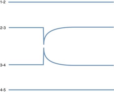
Although some artifacts can be recognized on the basis of the shapes of their waves, the most powerful tool in distinguishing a true brain wave from an artifact is to establish its specific topography. Here, the major operating principle is that biological events recorded on the scalp tend to have a point of maximum voltage with the surrounding measured voltages diminishing with varying steepness from the point of maximum (see Figure 6-1). The voltage gradients seen with electrocerebral events are expected to have some degree of “smoothness.” In contrast, the electric fields of artifacts may have a patchy and unpredictable contour (compare to Figure 6-2).
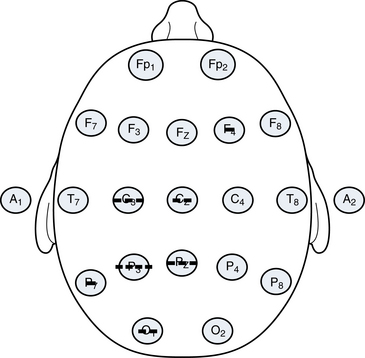
A second principle is that the polarity of most discharges tends to be consistent. Most discharges, if negative at their maximum point, remain negative wherever they are detected on the scalp as shown in Figure 6-1. In general, negative events tend to be negative everywhere, and positive events tend to be positive everywhere. Exceptions to this rule exist, including the occasional examples of discharges that manifest a so-called horizontal dipole (the example of the “horizontal” or tangential dipole is discussed in detail in Chapter 10, “The EEG in Epilepsy”). Even in the small minority of epileptiform events that manifest a simultaneous combined positivity and negativity, those areas of opposite charge are usually segregated in a simple and orderly fashion rather than showing a pattern of several separated regions of positivity and negativity (see Figure 6-3).
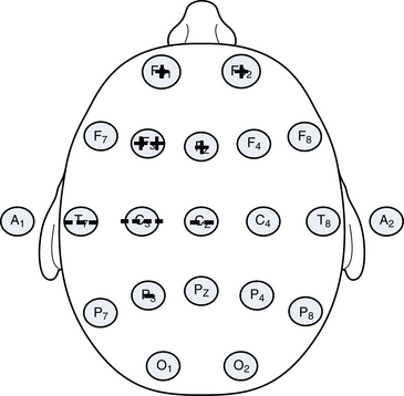
Figure 6-3 A schematic of a “horizontal dipole” is shown, a relatively uncommon finding outside of benign rolandic epilepsy and related syndromes. In contrast to most discharges that show a single polarity on the scalp at any one time (usually negative), in this example, a negative charge and a positive charge are recorded on the scalp simultaneously. Even though both polarities are present, the transition between the two is smooth. The configuration shown here of a negativity in the centrotemporal area and a positivity in the anterior head regions is characteristic of the so-called rolandic spike, discussed in more detail in Chapter 10, “The EEG in Epilepsy.”
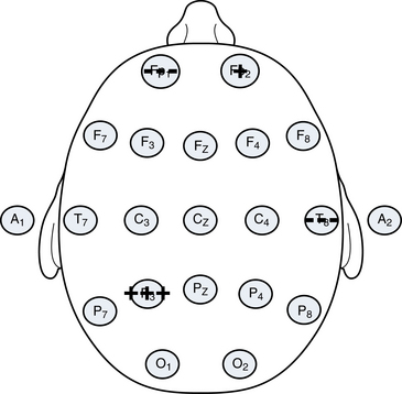
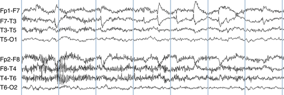
Patterns with significant charge inconsistencies are also not expected from biological systems. The example of an apparent discharge with strong negativities in the left posterior quadrant and the right anterior quadrant but no measured voltage change in the intervening areas as depicted in Figure 6-4 is not likely of cerebral origin. Because this is not a “biological” pattern, there would be a strong suspicion of motion or some other type of artifact having affected two distant electrodes. This pattern and the pattern that was seen in Figure 6-2 may be produced by the haphazard jostling of electrodes during patient movement.
Whenever analyzing any wave on the EEG page, the reader should visualize the voltage topography of the discharge to confirm a distribution of charge that is potentially consistent with cerebral activity. Usually with a bit of practice this can be done quickly. Discharges with bizarre or unpredictable electrical fields likely represent artifact. The importance of localization skills cannot be overemphasized and it is for this reason that the techniques of localization discussed in Chapter 4, “Electroencephalographic Localization,” should be mastered before moving on.
Some significant EEG diagnostic challenges occur when patients are referred for the question of whether sudden movements are epileptic. The diagnostic problem is made more difficult in that each movement may generate a motion artifact causing the appearance that each is correlated with an EEG burst. There would be no difficulty if the movement in question were, for instance, a nonepileptic twitching of the hand because a hand movement would not cause motion artifact in distant scalp electrodes. The hand movement would occur during the study, and there would be no EEG change, strongly suggesting that the hand movements were nonepileptic. If the movement involves the head, however, there may be a simultaneous burst in the EEG, creating some confusion as to whether the movement caused the wave (and is an artifact) or the wave caused the movement (and is an epileptiform discharge). The approach to this problem takes into account that when the head moves, is turned on the pillow, or is subject to some other type of external movement, the pattern of electrodes that are disturbed tends to be more random. Artifacts caused by electrode motion or head motion tend to show a nonregular distribution of inconsistent voltages like those shown in Figures 6-2 and 6-4. In comparison, the patterns associated with electrocerebral activity are expected to show more consistent polarities and a voltage gradient that tapers with distance from the point of maximum.
SPECIFIC TYPES OF EEG ARTIFACT
Artifacts Associated With Eye Movements
Eyeblink Artifact
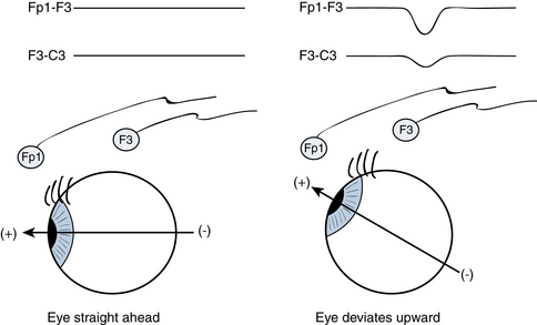
Electroencephalographers know that when individuals close their eyes, the globes of the eyes deviate upward. This comes as a surprise to some because when we watch a person casually blink or close the eyes, this upward movement of the globes is hidden from view by the closed eyelids. It is only in special situations that this reflex upward eye deviation with eye closure, termed Bell’s phenomenon, is readily observable. Bell’s phenomenon becomes strikingly evident in the case of individuals who suffer from Bell’s palsy. In Bell’s palsy, there is a paralysis of the facial nerve (cranial nerve VII), one of whose functions is to close the eyes. The nerves that move the globe of the eye (cranial nerves III, IV, and VI) are unaffected in patients with Bell’s palsy. Therefore, Bell’s palsy patients have normal eye movement but cannot close the affected eyelid. Thus, the facial nerve paralysis caused by Bell’s palsy literally uncovers Bell’s phenomenon—we can see what the globe of the eye is doing during intended eyelid closure. Bell’s palsy patients have normal eye closure on the unaffected side, but when blinking or closing the eye on the paralyzed side, the globe of the eye can be seen to deviate upward, unhidden by the eyelid. Upward deviation of the globes may also be seen when a person’s eyelids are forcibly pried open during attempted voluntary eye closure. Finally, in some individuals who are in the process of falling asleep, especially babies, the eyelids may lower to a “half-mast” position but do not completely close. Because of a partial Bell’s phenomenon associated with the partial eye closure, only the whites of the eyes can be seen in the half-open palpebral fissures.
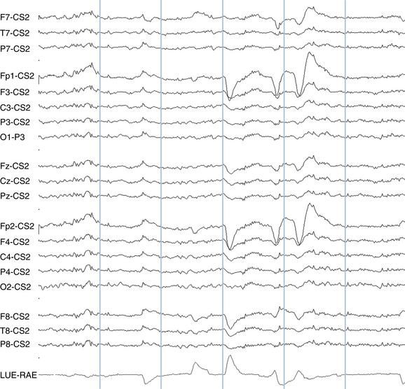
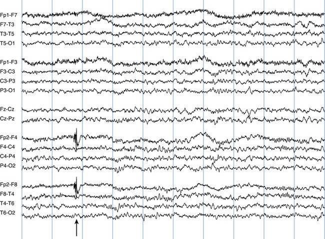
The type of artifact that an upward movement of the globes might cause during eye blinking or eye closure is not intuitively obvious without knowing that the globe of the eye has a particular distribution of charge. As it happens, the cornea (the front of the globe of the eye) carries a net positive charge and the posterior pole of the globe carries a net negative charge, forming a dipole. Because of the presence of this positive charge on the cornea, the bobbing upward of the eye with eye closure is easily detected by EEG electrodes. Figure 6-5 illustrates how the EEG electrodes closest to the eye “perceive” an eyeblink. With upward eye deviation, the electrodes closest to the globes, Fp1 and Fp2, perceive the strong positivity of the corneal surfaces. The F3 and F4 electrodes, which are immediately posterior to the Fp1 and Fp2 electrodes, also pick up some of this positivity, but to a much lesser degree than the Fp1 and Fp2 electrodes. With Fp1 being more positive than F3 and Fp2 being more positive than F4, the Fp1-F3 and Fp2-F4 channels show the characteristic sharp, downward-sweeping waveforms of eyeblink artifact (see Figure 6-6). A similar type of artifact is seen with eye fluttering (see Figure 6-7).
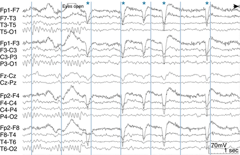
A useful general rule regarding eyeblink artifact is that it should not be detectable in the electrodes of the posterior half of the head; movements of the globes of the eye should not be perceived by the parietal or occipital electrodes because they are too distant. Eyeblink artifact is only occasionally picked up by the central electrodes, C3 and C4, and when it is it should be of low voltage (see Figure 6-8).
Lateral Eye Movement Artifact
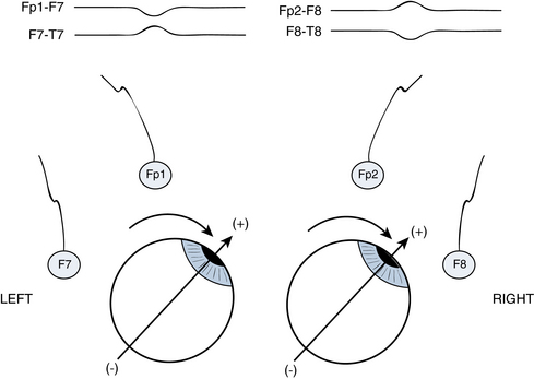
An extension of this same phenomenon involving the motion of the positive charge on the anterior aspect of the globe is used to understand the appearance of lateral eye movement artifact. In the case of lateral eye movements, the anterior temporal electrodes, F7 and F8, are the electrode contacts best placed to perceive the positivity of the cornea as the eyes move from side to side in the horizontal plane. For example, when a patient gazes to the left, the F7 electrode picks up a net positivity. Simultaneously, as the eyes gaze to the left, the F8 electrode picks up a net negativity from the posterior pole of the globe (see Figure 6-9). This results in a characteristic pattern seen with a simultaneous “positive phase reversal” in the anterior temporal electrode on the side to which the eyes have turned and a “negative phase reversal” in the anterior temporal electrode on the side away from which the eyes have turned. In the case of more rapid voluntary saccades or REM sleep, these lateral eye movement artifacts can have a squared-off appearance at wave onset. During drowsiness, slow roving lateral eye movements may be seen in which the artifact shows a more rounded appearance (see Figure 6-10). Therefore, identification of both eyeblink and lateral eye movement artifact requires a combination of wave pattern recognition and localization of the electrical events to their characteristic locations.
Slow Roving Eye Movements of Drowsiness and Sleep
Slow roving eye movements of drowsiness mentioned earlier represent an important example of lateral eye movement artifact. This type of eye movement shows an electrical pattern that is similar to other lateral eye movements, with a “positive phase reversal” at the anterior temporal electrode on the side to which the eyes are moving and a “negative phase reversal” at the opposite anterior temporal electrode. The slow roving version of lateral eye movements has a distinctively rounded, more prolonged shape (see Figure 6-10). In contrast, lateral eye movements occurring during wakefulness or during REM sleep tend to be quicker and have a more squared-off onset. Correct identification of eyeblink artifact and the various lateral eye movement artifacts can be helpful in determining sleep stage.
Nystagmus Artifact
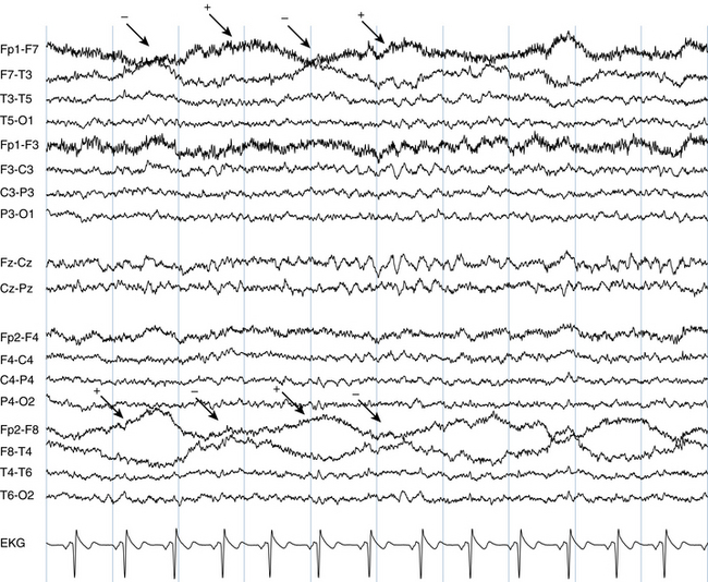
Nystagmus artifact is a special example of lateral eye movement artifact, identifiable by its rhythmicity. It is easy to distinguish from repetitive waveforms of cerebral origin based on its characteristic polarity in the anterior temporal electrodes (F7 and F8). Figure 6-11 shows a repetitive, rhythmic waveform for which the polarity of the phase reversal is opposite on the left and right sides at any given moment, indicating a repetitive lateral eye movement consistent with nystagmus.
Figure 6-11 The characteristic appearance of nystagmus is seen in the form of repetitive lateral eye movement artifact with sharp contours maximum in the anterior temporal electrodes, F7 and F8. Note the opposite polarities at any given time in the F7 and F8 electrodes and compare the more jagged contours of the eye movement artifact seen here with those of the slow roving lateral eye movements in Figure 6-10.
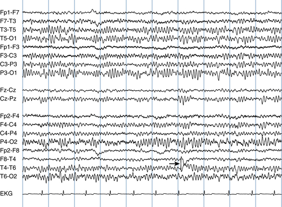
Lateral Rectus Spikes
In addition to the types of lateral eye movement artifacts described earlier, lateral eye movements may also cause an artifact that appears as a sharp transient in the anterior temporal area with each lateral eye movement (see Figures 6-12 and 6-13). This type of artifact is important to recognize so as not to mistake these sharp transients for true epileptic spikes. It is hypothesized that these sharp transients represent electromyogram (EMG or muscle) artifact from activation of the lateral rectus muscle during lateral eye movements.
Electrode Pops and Other Single Electrode Artifacts
Electrode Pops
Electrode pops may occur because of a buildup of static charge in an individual electrode followed by a quick release of that charge. Sometimes an electrode pops because it has been poorly applied, but frequently there is no clear explanation for electrode popping. Electrode pops often have a distinctive shape (see Figure 6-14), although the morphology of electrode pops may vary.
The key attribute of the electrode pop is the strict localization of the event to a single electrode. Because, by its nature, an electrode pop is confined to a single electrode, it is said to “have no field.” This is an important concept in artifact identification. A “biological” (brain wave) event usually manifests some amount of an electric field in at least some of the surrounding electrodes—the voltage of the event tapers away from the point of maximum in a more or less gradual fashion. However, if a wave is caused by a problem in a single electrode, be it a “pop” or a problem with the contact, the field of the event will be restricted to a single electrode; the adjacent electrodes perceive nothing at the moment of the “pop.”
Figure 6-15 shows an example of an electrical event completely restricted to a single electrode, T3. Careful scrutiny of surrounding electrodes reveals no evidence of an electric field or gradient in any of the adjacent electrodes (F7, T5, or C3). Another way of proving the isolation of this event is ask whether, if the two channels that include the T3 electrode were to be erased from the EEG, would it still be possible to identify the moment of the would-be spike? In this example, not even the smallest deflection in the adjacent channels can be seen, establishing this as a single electrode event representing and an electrical artifact rather than an electrical event of cerebral origin.
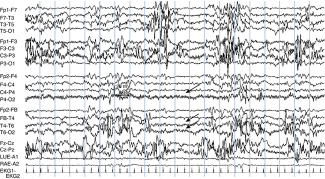
Although electrode popping often occurs as an isolated event, sometimes highly repetitive popping can occur which can resemble seizure activity. Figure 6-16 shows an example of repetitive electrode popping in the P4 electrode. Note that the adjacent electrodes, O2, C4, and T6, show no evidence of the deflection. The same effect is seen in Figure 6-17—a deflection that has some resemblance to a spike-wave discharge in T4 is seen to be an electrode pop on closer analysis. Figure 6-18 shows a high voltage, complex waveform confined to the Fp2 electrode. Again, because this waveform is of moderately high voltage but cannot be detected in the adjacent channels (Fz-Cz, F4-C4, and F8-T4), these deflections are correctly interpreted as an artifact in the Fp2 electrode.

The Single “Bad Electrode”
A poor electrode contact can cause a distinctive, high-voltage pattern in which adjacent channels in a bipolar montage appear to mirror one another (see Figure 6-19). In this example, the high-voltage pattern seen in the F3-C3 channel is mirrored in the C3-P3 channel implying a poor electrode contact at C3. It is especially useful to recognize the patterns caused by a poor electrode contact when it only occurs intermittently in a tracing. Knowing that there is a poor contact in C3, the alert reader immediately becomes suspicious of any high-voltage deflection that may be seen at any other time in that electrode, realizing that it could represent electrode artifact from the poor contact.
OTHER TYPES OF ARTIFACT
Muscle Artifact
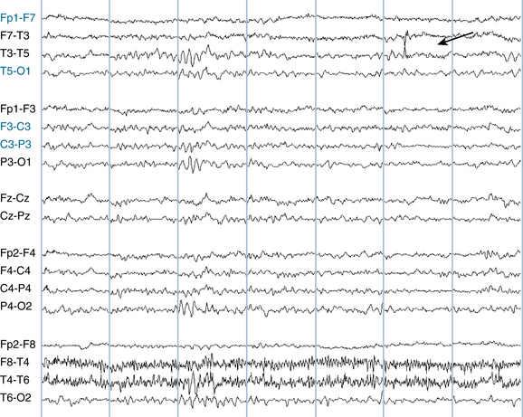
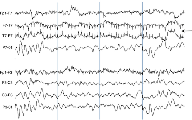
Muscle artifact is one of the most commonly encountered artifacts in the EEG and is especially common during wakefulness. Muscle artifact is recorded most often by electrodes that overlie the muscles of the scalp: the frontalis, temporalis, and occipitalis muscles. The frontopolar and midtemporal electrodes, Fp1, Fp2, T7, and T8 are most frequently affected (as was seen in Figure 6-7), but most others can be affected as well. Because there is almost no muscle over the vertex of the skull, muscle artifact is usually not seen in the midline (Cz, and Pz) electrodes.
Muscle artifact appears as a fast wave that appears to “turn the channel black.” Occasionally muscle artifact can be difficult to distinguish from a train of rapid spikes, although certain characteristics help make the distinction. Muscle artifact usually fires at a fast, uncountable rate, and it can be difficult to appreciate a specific wave morphology from within this rapidly firing, heterogeneous mixture of waves. Instead, muscle artifact usually consists of a mixture of spike-like potentials with variable shape and height. An interesting exception to this rule is the repetitively firing isolated motor unit. This type of artifact appears as a repetitive, low-voltage monomorphic spike that has a stuttering firing frequency and may persist for varying lengths of time. Although the firing rate does vary, it does not show sustained trends toward speeding up or slowing down as seizures tend to do (see Figures 6-20 and 6-21). Motor unit spikes usually do not have an electric field, that is, they are not seen in adjacent electrodes. When seen over the temporalis muscle, they may be terminated by asking the patient to relax the jaw, although the firing of an individual motor unit may not be easily under the patient’s control.
Sweat Artifact
A patient who is sweating may manifest an artifact that consists of long duration, high-voltage potentials recognizable by their distinctive, prolonged shape (see Figure 6-22). This slow, swaying artifact is caused by electrolyte bridges that form between adjacent electrodes because of excess sweating. Sweat artifact can be eliminated by anything that stops the patient from sweating, including cooling the room where the EEG is being performed.
EKG Artifact
EKG artifact is usually easy to identify. Its most distinctive features are its shape and its rhythmicity. Most EEG tracings are recorded with an EKG channel. Suspicion that a spike is really an example of EKG artifact can be confirmed by matching the timing of the deflection in question with the QRS complex in the EKG channel. Also, the width of EKG artifact should be similar to the width of the QRS complex in the EKG channel (see Figures 6-23 and 6-24, A and B).
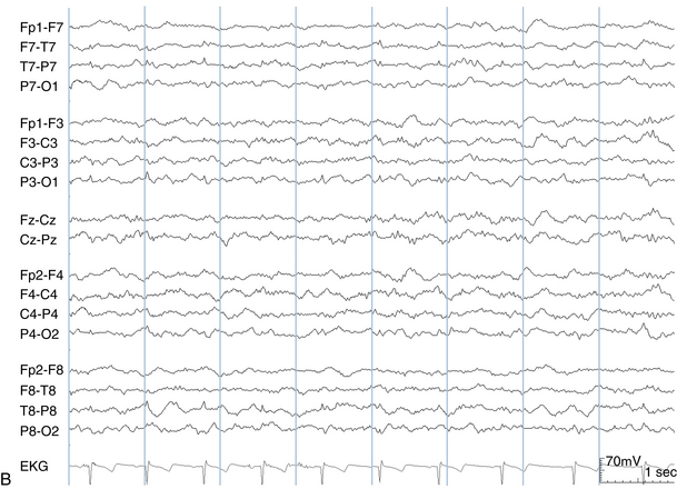
EKG artifact tends to occur in certain contexts. Because the heart is on the left side of the body in most patients and the left ventricle makes a bigger contribution to the QRS complex than the right ventricle, the left temporal electrodes are more likely to pick up this type of artifact. Patients with higher voltage QRS complexes from ventricular hypertrophy may have greater degrees of EKG contamination in the scalp; in those with right ventricular hypertrophy, the EKG artifact may be more prominent on the right side of the head. Also, patients with wider necks tend to transmit EKG artifact more readily to the head. Finally, the height of the EKG complexes as measured on the scalp tend to vary with the respiratory cycle.
Apart from the situation of poorly applied electrodes, EKG artifact would be expected to appear when any two regions of the scalp are compared that carry different amounts of EKG signal for anatomical reasons. The most common example of this is seen in the transverse bipolar montage in the channel where the left earlobe is compared with the left midtemporal electrode (A1-T7). For anatomical reasons, the left earlobe carries less EKG signal than the left midtemporal area. Because of the left-sided orientation of the heart, the same effect is seen less dramatically on the opposite side, where T8 is compared with A2 (see Figure 6-24). Among all the electrode pairs in standard bipolar chains, these pairings are the most likely to manifest EKG artifact in normal patients with well-applied electrodes.
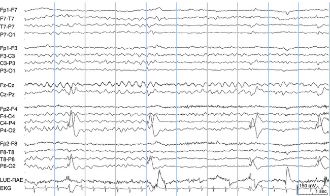
Pulse Artifact
Pulse artifact is seen when one electrode happens to be placed directly on an artery in the scalp (often the temporal artery), creating an artifactual waveform related to the pulsations. This type of artifact has also been called the hemoballistogram. In this case, a wide pulse artifact is seen in synchrony with the EKG. When an EKG channel is present, it is easy to link this artifact to the heart rate (note that the pulse artifact does not occur at the exact moment of the EKG but follows it by a set interval). Even when there is no EKG channel, this type of artifact is still usually easy to identify based on its heartbeat-like rhythm, the fact that it is much wider than the QRS complex of the EKG, and its presence in a single electrode (see Figure 6-25). More rarely, a related type of movement artifact may be seen that is synchronized to the patient’s EKG in cases in which the patient’s body makes a low-amplitude rocking movement with a hyperdynamic heartbeat.
60-Hz Artifact
The problem of 60-Hz artifact is discussed in more detail in Chapter 7, “Filters in the EEG,” as a specific filter is available to help suppress this type of artifact. Small amounts of AC current from the power mains that surround the patient flow through the patient’s body accounting for this type of artifact. (In countries that use line frequencies of 50 Hz, 50-Hz artifact is seen instead.) Because this small amount of 60-Hz current is present in similar amounts throughout the body, this signal is usually canceled out by the subtraction process used by the common mode rejection amplifiers in the same way that EKG artifact is canceled out as described earlier. Here again and similar to the case of EKG artifact, a poorly applied electrode is more likely to manifest 60-Hz artifact because of the difference between the amount of 60-Hz activity the poorly applied electrode picks up compared with its neighboring well-applied electrodes. As with the unexpected appearance of EKG artifact in an isolated electrode as described earlier, the presence of 60-Hz artifact only in channels that include a particular electrode suggests that that electrode may have a poor contact (see Figures 6-26 and 6-27).
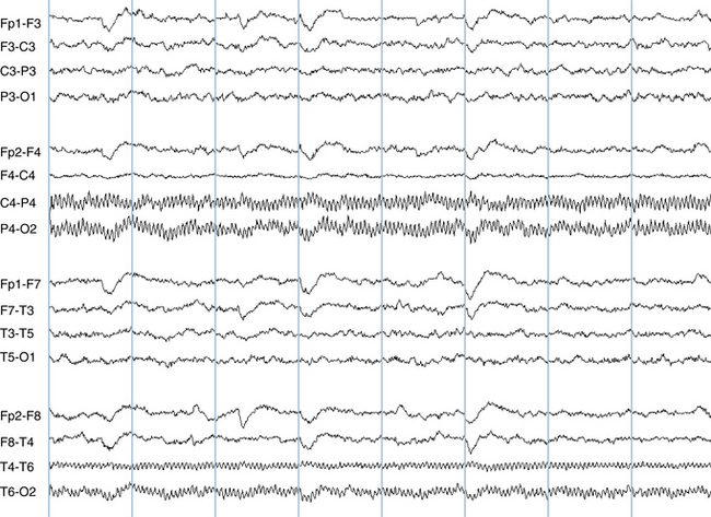
Figure 6-26 Prominent 60-Hz artifact is seen in the P4 and T6 electrodes. At first glance, 60-Hz artifact can be mistaken for muscle artifact, but the highly regular, sinusoidal pattern of the waves in these channels is not consistent with muscle activity. Sixty-hertz artifact may be seen at exactly 60 Hz, or as a subharmonic of 60 Hz. In this example the artifact has a frequency of exactly 20 Hz. Sixty-hertz artifact can often be eliminated after the fact with the use of a 60-Hz notch filter (see Chapter 7, “Filters in the EEG”).
Special Types of Motion Artifact
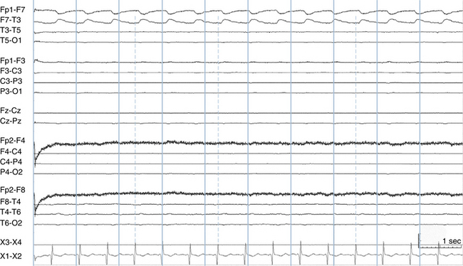
Certain types of motion artifact are seen fairly frequently in the EEG. Respiratory artifact occurs when breathing motions cause a gentle rocking of the head with each breath. Usually, the electrodes in contact with the bed (often the occipital or temporal electrodes) are preferentially involved. Linking the occurrence of what is usually a broad artifactual wave to the respiratory cycle can establish the source of this type of artifact. This task is made considerably easier when a respiratory channel is in use. Ventilator artifact can be considered a subset of either respiratory artifact or motion artifact; wave artifacts are created by body movements induced by the ventilator. A special case of ventilator artifact is seen with high-frequency ventilators, which can cause high-frequency motion artifacts (see Figures 6-28 and 6-29).
Patting artifact occurs most frequently in children but is also seen in adults. When the patient’s back is patted, a repetitive and regular motion artifact may appear in the EEG (see Figure 6-30). Chest physical therapy artifact may also cause a similar appearance. Usually, patting rhythms are maintained fairly regularly throughout their duration; it is uncommon for a caregiver’s patting rate to increase or decrease substantially throughout its course, and abrupt pauses are more common (see Figure 6-31). This differs from seizure activity, which tends to gradually evolve in frequency throughout its course. The implied polarity of patting artifact waves usually is not “biologically plausible” for electrocerebral activity.
Hiccup Artifact
Hiccup artifact is a special type of motion artifact associated with hiccuping. Because each hiccup usually causes a similar movement in the patient, the EEG artifact caused by hiccuping is often stereotyped (see Figure 6-32). Occasionally hiccup artifact may resemble a polyspike discharge, but the field of the artifact is usually irregular enough that the distinction is not difficult.
Breach Rhythm
The breach rhythm is a distinctive rhythm that can be considered an artifact of a skull defect, usually from a previous neurosurgical procedure. Defects in the skull tend to allow preferential transmission of high-frequency activities. For this reason, higher voltage fast rhythms may be present over the area of a previous craniotomy site. Breach rhythms are discussed in more detail in Chapter 11, “Normal Variants in the EEG.”
Chewing and Bruxism Artifact
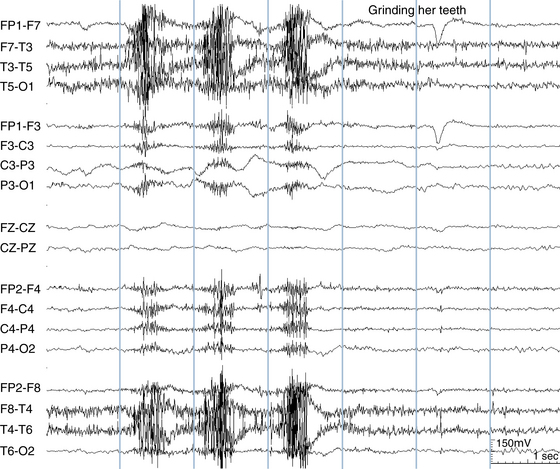
Chewing artifact is usually easy to recognize, appearing as brief, repetitive muscle bursts, maximum in the temporal areas (see Figure 6-33). Chewing artifact can be seen while the patient is eating but sometimes occurs as a “nervous habit” even when the patient has nothing in his or her mouth. Chewing artifact may also be seen associated with chewing automatisms during complex partial seizures. Bruxism (tooth grinding) usually occurs during sleep, but may also be seen during wakefulness, especially in the mentally retarded population. Its appearance is similar to chewing artifact because both involve rhythmic tensing of the jaw muscles. Bruxism artifact is of longer duration and occurs at a slower pace than chewing artifact (see Figure 6-34).
Figure 6-33 Chewing movements create rhythmic bursts of muscle artifact maximum over the temporalis muscle.
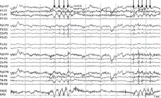
Glossokinetic Artifact
Glossokinetic artifact is generated by movements of the tongue, which also has a net dipole (much like the globe of the eye), with the tip of the tongue being negative relative to the base. The appearance of this artifact in a tracing can be confirmed by having the patient reproduce it on the EEG by request. The patient is asked to move the tongue forward in the mouth repetitively by repeating syllables such as “la-la-la” or “ta-ta-ta.” The field of glossokinetic artifact can extend over the whole scalp and can be recorded at highest voltage by electrodes placed on the face (see Figure 6-35).