26 Echocardiographic Guidance of Procedures
Jugular Venous Cannulation


Sequence
 Place the patient in Trendelenburg position to increase the size of the neck veins.
 With the skin cleaned and sterile, introduce the probe into a sterile plastic sheath.


 The vein is identified by the following:


 Visualize the wire extending from the needle.
 Visualize the sheath within the lumen following its insertion.


Endomyocardial Biopsy
To reliably diagnose heart transplant rejection, right ventricular endomyocardial biopsy (percutaneous procurement of endomyocardial samples from the right ventricle1,2) remains the gold standard. Right ventricular endomyocardial biopsy also is a valuable way to assist with diagnosis and management of suspected myocarditis, infiltrative cardiomyopathy, or other unexplained ventricular dysfunction.
Percutaneous right ventricular endomyocardial biopsy most commonly is performed using cannulation of the right internal jugular vein. In circumstances where this vessel is not usable, the femoral vein can be used for this purpose. Cardiologists traditionally have relied on fluoroscopic guidance for placement of the bioptome. Using frontal-plane fluoroscopic guidance, the bioptome is directed toward the right ventricular septum to obtain right ventricular samples. Bioptome contact with the right ventricular septum is confirmed by the presence of ventricular ectopic beats, and samples are taken from that site. Typically at least four biopsy samples are obtained, because a minimum of three adequate biopsy samples are required for histologic diagnosis. The use of fluoroscopy to guide right ventricular endomyocardial biopsy has a number of drawbacks: it provides only approximate bioptome placement information; exposes both the patient and physician to radiation; and requires use of the cardiac catheterization laboratory—a facility in high demand. Using fluoroscopic guidance, the complication rate ranges from 6% to 14%,3,4 with possible complications including myocardial perforation, tricuspid valve apparatus disruption, arrhythmias, coronary artery to right ventricular fistula, and inadvertent arterial punctures. A significant limitation of fluoroscopic guidance for right ventricular endomyocardial biopsies is that the bioptome placement and subsequent sampling area are limited due to inability to place the bioptome precisely, leading to repeated sampling from the same area. This contributes to biopsies that consist predominantly of scar from previous biopsy sites, which are inadequate for histologic assessment, and to reduced sensitivity due to the potentially focal nature of rejection or other cardiac histologic processes.


Sequence
 Echocardiographically guided endomyocardial biopsy usually is performed in the echocardiography laboratory, with the assistance of an echosonographer and a nurse.


 The bioptome is then inserted through the venous sheath into the right atrium.


Two decades ago, Miller published his successful results using echocardiographic guidance for right ventricular endomyocardial biopsy.5 Despite this and other reports of reduced costs and an improved safety profile using echocardiography to guide right ventricular endomyocardial biopsy in adults and children,6–10 this technique has not gained widespread popularity.
Pros

 Provision of additional information


Despite valid and compelling benefits, there has been reluctance to adopt echocardiographically guided right ventricular biopsy. A typical argument against the technique is the perception that it is difficult to get adequate echocardiographic images in some patients. In 90% of patients, however, the standard apical four-chamber view can be used to view the bioptome head,6 although modifications of this view may be necessary to provide optimal imaging during bioptome manipulation.


Pericardiocentesis

Sequence


Transseptal Puncture
Rationale and Role


Sequence
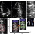
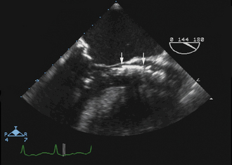
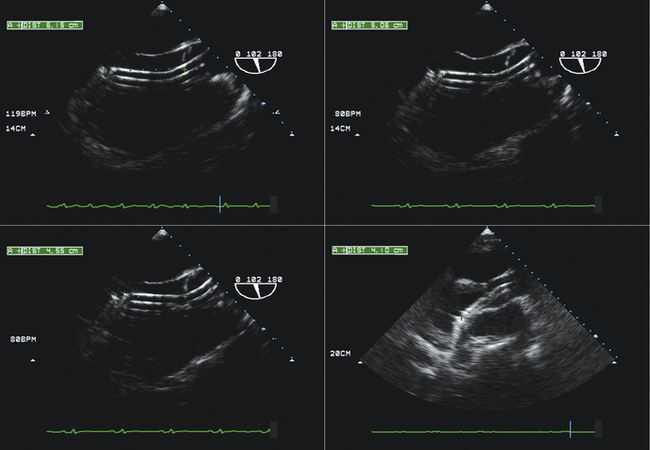
 Visualization of the catheter and needle approaching the heart (inferior vena cava/bicaval view)
 Visualization of the needle contacting the interatrial septum away from the margin of the septum
 Visualization of the needle tenting the interatrial septum away from the margin of the septum
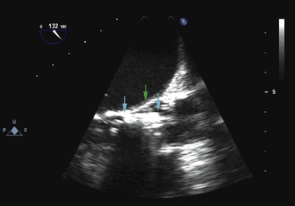
 Visualization of the needle/catheter in the left atrium
 Visualization of the catheter flush (small bubbles) in the left atrium


Catheter Mitral Balloon Valvuloplasty


Percutaneous Aortic Valvuloplasty


Sequence
Preprocedural Assessment
Severity/morphology of aortic stenosis


TEE may be required to yield accurate root dimensions if TTE is technically difficult. The contribution of gated cardiac CT also should be considered for dimensional measurements
The number of key measurements depends on the PAV used:

 For the Edwards-Sapien prosthesis
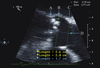
The aortic annulus is a critical measurement in determining patient eligibility and is useful in device sizing. The aortic annulus is not a planar anatomic structure but, rather, a complex 3-dimensional “crown-like” configuration formed by the insertion of the aortic cusps into the aortic wall. Small variations in image plane can produce significantly differing annular measurements. Hence, careful alignment of the aortic root is essential in producing an accurate and reproducible measurement.
 Parasternal long-axis view on TTE and the midesophageal long-axis view on TEE


Our recommendation is to obtain three reproducible measurements:


 Aortic valve area–ostial height
 These dimensions are critical for sizing the percutaneous prosthesis.


Other valve pathology/cardiac disease


Intraprocedural Role
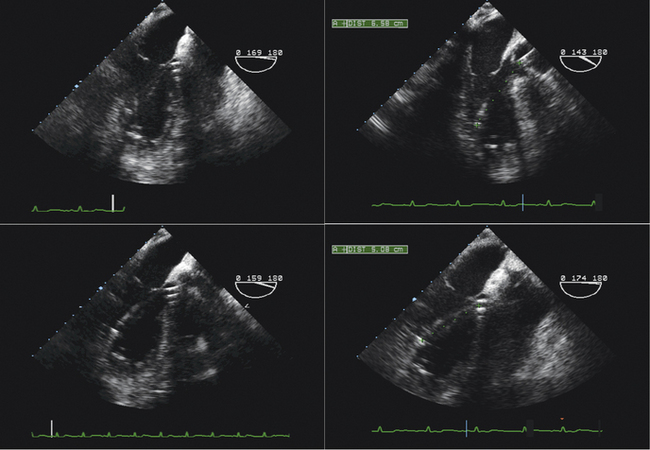
 The long-axis view (~130 degrees) is used to guide deployment of the Edwards prosthesis. Ideally, the undeployed Edwards valve on the delivery system should be positioned across the aortic valve coaxial to the aorta. The ventricular end should be positioned up to 5 mm below the native aortic valve area, because there is a tendency for the percutaneous heart valve (PHV) deployment system to propagate incrementally toward the aortic root during deployment. The aortic end should be close to the tips of the native aortic valve leaflets to ensure full leaflet capture with deployment.

 Hemodynamic instability often is observed during device positioning. This may be due to critical output obstruction by the undeployed PHV, but is thought sometimes to be related to reflexive changes in vagal output. Correct deployment position of the Edwards valve is essential so that the fabric portion of the prosthesis is fully opposed to the aortic annulus. Deployment in a position that is too ventricular is serious; it may result in immediate and life-threatening aortic regurgitation; incomplete capture of native aortic valve leaflets and restriction of anterior mitral valve leaflet motion also may be seen. Deployment in a position that is too aortic can result in coronary artery obstruction and can compromise the stability of the valve, risking valve embolization.
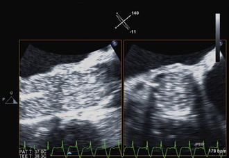
 Edwards-Sapien valves usually are implanted under TEE guidance:

Post-procedural Assessment
 Immediate post-procedural assessment by TEE


Intra-Aortic Counterpulsation Balloon Tip Localization

Sequence


Impella and Left Ventricular Assist Device Insertion*
Rationale and Role
 The Impella percutaneous ventricular assist devices (Abiomed, Inc., Danvers, MA) typically are inserted percutaneously via the femoral artery (Impella 2.5) or via surgical cut-down (Impella 2.5 or 5). The device is advanced retrograde up the aorta, and positioned across the aortic valve such that the intake is within the LV, and the output is above the aortic valve. The component of the device within the LV is best oriented along the long axis of the LV. The presence of significant aortic insufficiency would preclude the device achieving efficiency.


Sequence
Transthoracic echocardiography
 To exclude significant aortic valvar stenosis
 To exclude significant aortic valvar insufficiency
 To exclude ‘mechanical’ complications of infarction
Transesophageal echocardiography
 After exclusion of significant aortic valve disease and mechanical complications of infarction
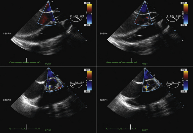
 The location of the intake can be determined as follows:

 Confirm that the output component is ejecting blood within the aorta beyond the aortic valve.
Pros


Surgical Ventricular Assist Device Placement and Function


Cons

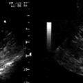
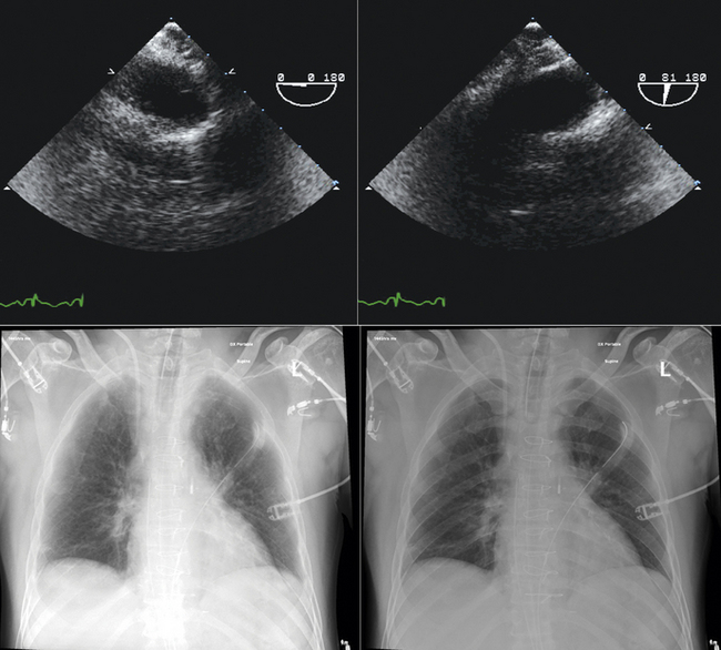
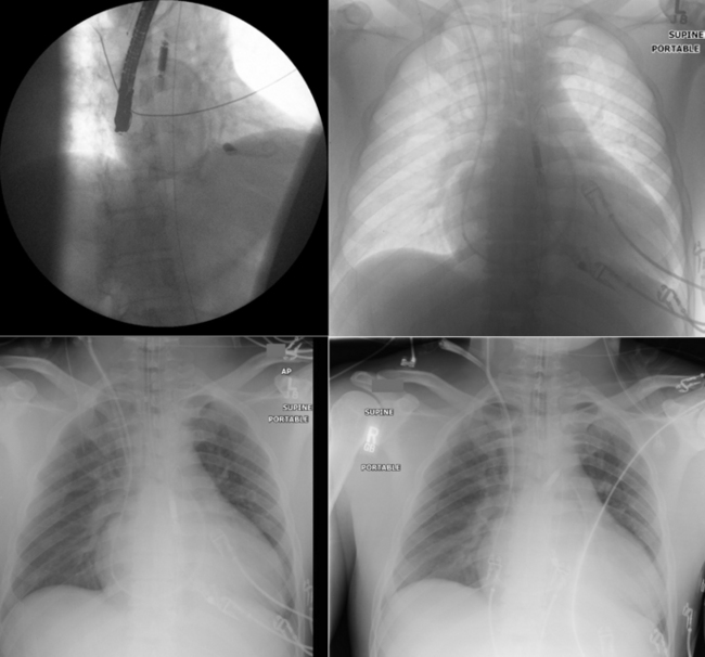
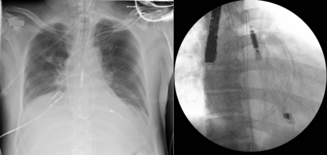
 Fluoroscopy generally is used to guide IABP placement, especially because most are placed in the cardiac catheterization laboratory. The role of TEE is limited to verification of correct placement without fluoroscopy (Fig. 26-41).
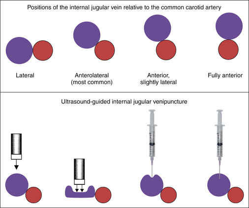
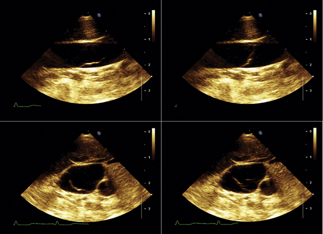
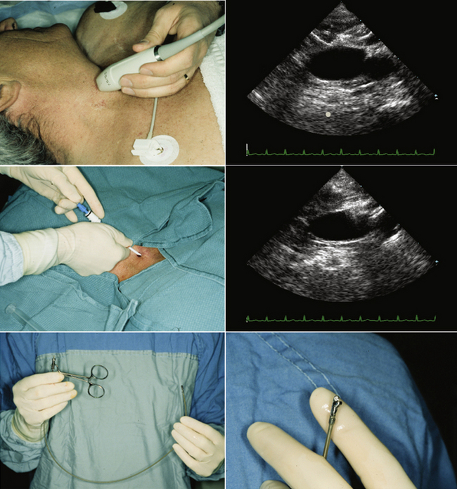
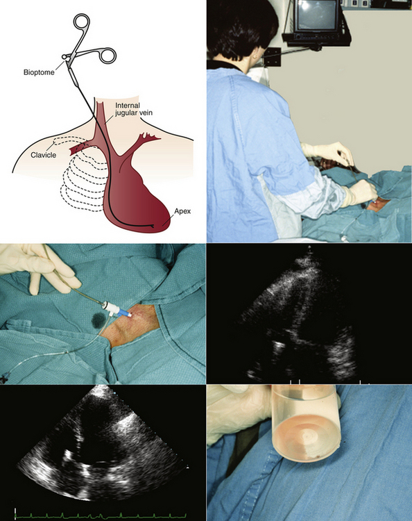
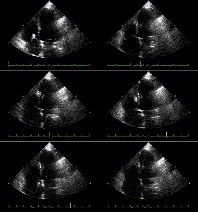
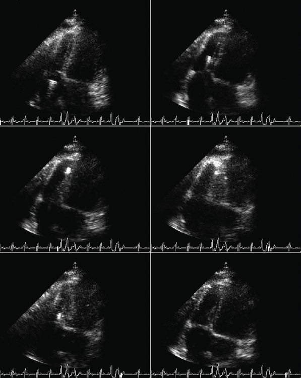
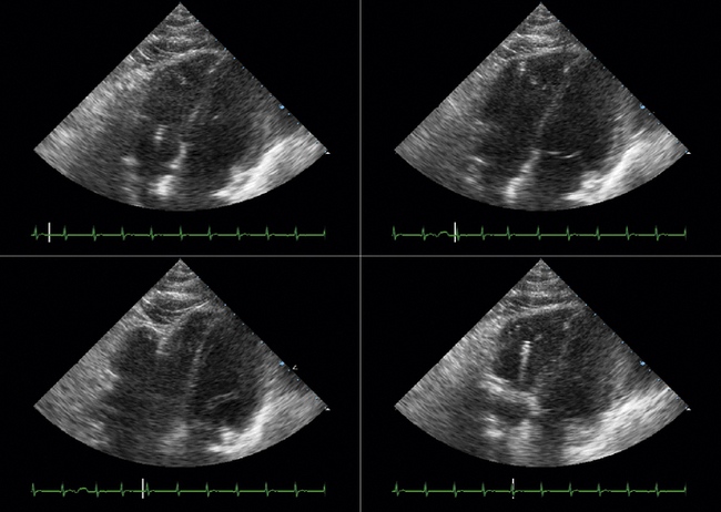
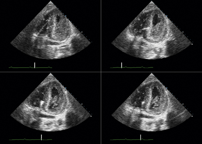
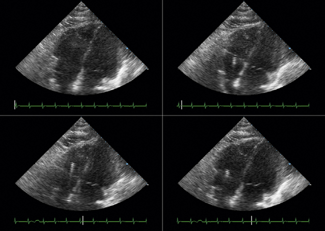
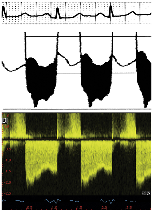
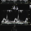
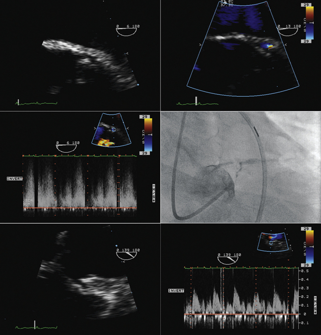
Figure 26-21 Mitral valve gradients and the corresponding spectral Doppler display, which yields gradient calculation.
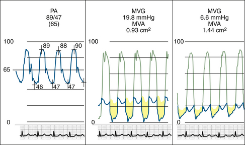
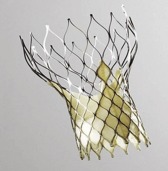
Figure 26-23 The CoreValve prosthesis.
(Courtesy of CoreValve ReValving System, CoreValve Inc., Irvine, California.)
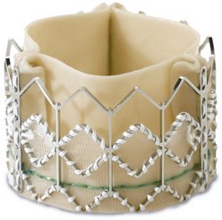
Figure 26-24 The Edwards-Sapien prosthesis.
(Courtesy of Edwards Life-Sciences Inc., Irvine, California.)
1. Caves P.K., Stinson E.B., Billingham M., Shumway N.E. Percutaneous transvenous endomyocardial biopsy in human heart recipients. Experience with a new technique. Ann Thorac Surg. 1973;16(4):325-336.
2. Billingham M. Endomyocardial biopsy diagnosis of acute rejection in cardiac allografts. Prog Cardiovasc Dis. 2009;33:11-18.
3. Deckers J.W., Hare J.M., Baughman K.L. Complications of transvenous right ventricular endomyocardial biopsy in adult patients with cardiomyopathy: a seven-year survey of 546 consecutive diagnostic procedures in a tertiary referral center. J Am Coll Cardiol. 1992;19(1):43-47.
4. Sakakibara S., Konno S. Endomyocardial biopsy. Jpn Heart J. 1962;3:537-543.
5. Miller L.W., Labovitz A.J., McBride L.A., et al. Echocardiography-guided endomyocardial biopsy. A 5-year experience. Circulation. 1988;78(5 Pt 2):III99-III102.
6. Blomstrom-Lundqvist C., Noor A.M., Eskilsson J., Persson S. Safety of transvenous right ventricular endomyocardial biopsy guided by two-dimensional echocardiography. Clin Cardiol. 1993;16(6):487-492.
7. Weston M.W. Comparison of costs and charges for fluoroscopic- and echocardiographic-guided endomyocardial biopsy. Am J Cardiol. 1994;74(8):839-840.
8. Williams G.A., Kaintz R.P., Habermehl K.K., et al. Clinical experience with two-dimensional echocardiography to guide endomyocardial biopsy. Clin Cardiol. 1985;8(3):137-140.
9. Ragni T., Martinelli L., Goggi C., et al. Echo-controlled endomyocardial biopsy. J Heart Transplant. 1990;9(5):538-542.
10. Appleton R.S., Miller L.W., Nouri S., et al. Endomyocardial biopsies in pediatric patients with no irradiation. Use of internal jugular venous approach and echocardiographic guidance. Transplantation. 1991;51(2):309-311.