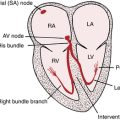
Chapter 3 ECG Leads
Please go to expertconsult.com for supplemental chapter material.
As discussed in Chapter 1, the heart produces electrical currents similar to the familiar dry cell battery. The strength or voltage of these currents and the way they are distributed throughout the body over time can be measured by a suitable recording instrument such as an electrocardiograph.
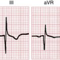
Taking an ECG is like recording an event, such as a baseball game, with an array of video cameras. Multiple camera angles are necessary to capture the event completely. One view is not enough. Similarly, multiple ECG leads must be recorded to describe the electrical activity of the heart adequately. Figure 3-1 shows the ECG patterns that are obtained when electrodes are placed at various points on the chest. Notice that each lead (equivalent to a different camera angle) presents a different pattern.
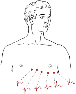
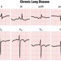
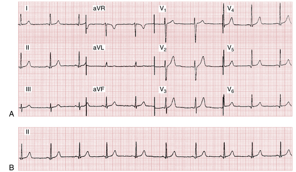
Figure 3-2 is an ECG illustrating the 12 leads. The leads can be subdivided into two groups: the six limb (extremity) leads (shown in the left two columns) and the six chest (precordial) leads (shown in the right two columns).
Limb (Extremity) Leads
Standard Limb Leads: I, II, and III
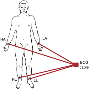
The extremity leads are recorded first. In connecting a patient to an electrocardiograph, first place metal electrodes on the arms and legs. The right leg electrode functions solely as an electrical ground, so you need concern yourself with it no further. As shown in Figure 3-3, the arm electrodes are attached just above the wrist and the leg electrodes are attached above the ankles.

Lead II records the difference between the left leg (LL) and right arm (RA) electrodes:

Lead III records the difference between the left leg (LL) and left arm (LA) electrodes:

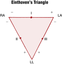
Leads I, II, and III can be represented schematically in terms of a triangle, called Einthoven’s triangle after the Dutch physiologist (1860-1927) who invented the electrocardiograph. At first the ECG consisted only of recordings from leads I, II, and III. Einthoven’s triangle (Fig. 3-4) shows the spatial orientation of the three standard limb leads (I, II, and III). As you can see, lead I points horizontally. Its left pole (LA) is positive and its right pole (RA) is negative. Therefore, lead I = LA − RA. Lead II points diagonally downward. Its lower pole (LL) is positive and its upper pole (RA) is negative. Therefore, lead II = LL − RA. Lead III also points diagonally downward. Its lower pole (LL) is positive and its upper pole (LA) is negative. Therefore, lead III = LL − LA.

In other words, add the voltage in lead I to that in lead III and you get the voltage in lead II.∗
You can test this equation by looking at Figure 3-2. Add the voltage of the R wave in lead I (+9 mm) to the voltage of the R wave in lead III (+4 mm) and you get +13 mm, the voltage of the R wave in lead II. You can do the same with the voltages of the P waves and T waves.


Thus, in electrocardiography, one plus three equals two.
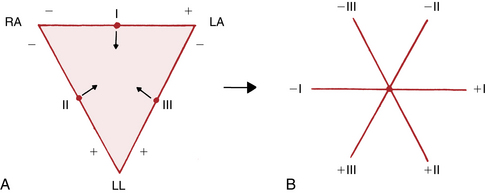
In Figure 3-5, Einthoven’s triangle has been redrawn so that leads I, II, and III intersect at a common central point. This was done simply by sliding lead I downward, lead II rightward, and lead III leftward. The result is the triaxial diagram in Figure 3-5B. This diagram, a useful way of representing the three bipolar leads, is employed in Chapter 5 to help measure the QRS axis.
Augmented Limb Leads: aVR, aVL, and aVF
A so-called unipolar lead records the electrical voltages at one location relative to an electrode with close to zero potential rather than relative to the voltages at another single extremity, as in the case of the bipolar extremity leads.∗ The zero potential is obtained inside the electrocardiograph by joining the three extremity leads to a central terminal. Because the sum of the voltages of RA, LA, and LL equals zero, the central terminal has a zero voltage. The aVR, aVL, and aVF leads are derived in a slightly different way because the voltages recorded by the electrocardiograph have been augmented 50% over the actual voltages detected at each extremity. This augmentation is also done electronically inside the electrocardiograph.†
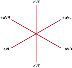
Just as Einthoven’s triangle represents the spatial orientation of the three standard limb leads, the diagram in Figure 3-6 represents the spatial orientation of the three augmented extremity leads. Notice that each of these unipolar leads can also be represented by a line (axis) with a positive and negative pole. Because the diagram has three axes, it is also called a triaxial diagram.

In other words, when the three augmented limb leads are recorded, their voltages should total zero. Thus, the sum of the P wave voltages is zero, the sum of the QRS voltages is zero, and the sum of the T wave voltages is zero. Using Figure 3-2, test this equation by adding the QRS voltages in the three unipolar extremity leads (aVR, aVL, and aVF).
Thus, the axis of lead I is oriented horizontally, and the axis of lead aVR points diagonally downward. The orientation of the standard (bipolar) leads is shown in Einthoven’s triangle (see Fig. 3-5), and the orientation of the augmented (unipolar) extremity leads is diagrammed in Figure 3-6.
The second major feature of the ECG leads, their polarity, can be represented by a line (axis) with a positive and a negative pole. (The polarity and spatial orientation of the leads are discussed further in Chapters 4 and 5 when the normal ECG patterns seen in each lead are considered and the concept of electrical axis is explored.)
Do not be confused by the difference in meaning between ECG electrodes and ECG leads. An electrode is simply the the paste-on disk or metal plate used to detect the electrical currents of the heart in any location. An ECG lead shows the differences in voltage detected by electrodes (or sets of electrodes). For example, lead I records the differences in voltage detected by the left and right arm electrodes. Therefore, a lead is a means of recording the differences in cardiac voltages obtained by different electrodes. For electronic pacemakers, discussed in Chapter 21, the terms lead and electrode are used interchangeably.
Relationship of Extremity Leads
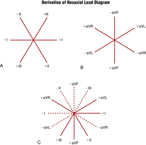
Einthoven’s triangle in Figure 3-4 shows the relationship of the three standard limb leads (I, II, and III). Similarly, the triaxial diagram in Figure 3-7 shows the relationship of the three augmented limb leads (aVR, aVL, and aVF). For convenience, these two diagrams can be combined so that the axes of all six limb leads intersect at a common point. The result is the hexaxial lead diagram shown in Figure 3-7. The hexaxial diagram shows the spatial orientation of the six extremity leads (I, II, III, aVR, aVL, and aVF).

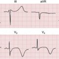
lead aVR usually shows an rS pattern

Finally, the pattern shown by lead aVF usually but not always resembles that shown by lead III.
Chest (Precordial) Leads
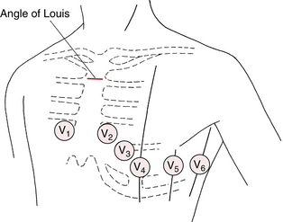
The chest leads (V1 to V6) show the electrical currents of the heart as detected by electrodes placed at different positions on the chest wall. The precordial leads used today are also considered as unipolar leads in that they measure the voltage in any one location relative to about zero potential (Box 3-1). The chest leads are recorded simply by means of electrodes at six designated locations on the chest wall (Fig. 3-8).∗
BOX 3-1 Conventional Placement of ECG Chest Leads
• Lead V1 is recorded with the electrode in the fourth intercostal space just to the right of the sternum.
• Lead V2 is recorded with the electrode in the fourth intercostal space just to the left of the sternum.
• Lead V3 is recorded on a line midway between leads V2 and V4.
• Lead V4 is recorded in the midclavicular line in the fifth interspace.
• Lead V5 is recorded in the anterior axillary line at the same level as lead V4.
• Lead V6 is recorded in the midaxillary line at the same level as lead V4.
Two additional points are worth mentioning here:
1. The fourth intercostal space can be located by placing your finger at the top of the sternum and moving it slowly downward. After you move your finger down about 1½ inches, you can feel a slight horizontal ridge. This is called the angle of Louis, which is located where the manubrium joins the body of the sternum (see Fig. 3-8). The second intercostal space is just below and lateral to this point. Move down two more spaces. You are now in the fourth interspace and ready to place lead V4.
2. Chest lead placement in females is complicated by breast tissue, which may result in misplacement of the chest leads. In taking ECGs on women, you must remember to place the electrode under the breast for leads V3 to V6. If, as often happens, the electrode is placed on the breast, electrical voltages from higher interspaces are recorded. Also, never use the nipples to locate the position of any of the chest lead electrodes, even in men, because nipple location varies greatly in different persons.
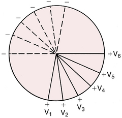
The chest leads, like the six extremity leads, can be represented diagrammatically (Fig. 3-9). Like the other leads, each chest lead has a positive and negative pole. The positive pole of each chest lead points anteriorly, toward the front of the chest. The negative pole of each chest lead points posteriorly, toward the back (see the dashed lines in Fig. 3-9).
The 12-Lead ECG: Frontal and Horizontal Plane Leads
The importance of multiple leads is illustrated in the diagnosis of myocardial infarction (MI). An MI typically affects one localized portion of either the anterior or inferior portion of the left ventricle. The ECG changes produced by an anterior MI are usually best shown by the chest leads, which are close to and face the injured anterior surface of the heart. The changes seen with an inferior MI usually appear only in leads such as II, III, and aVF, which face the injured inferior surface of the heart (see Chapters 8 and 9). The 12 leads therefore provide a three-dimensional view of the electrical activity of the heart.
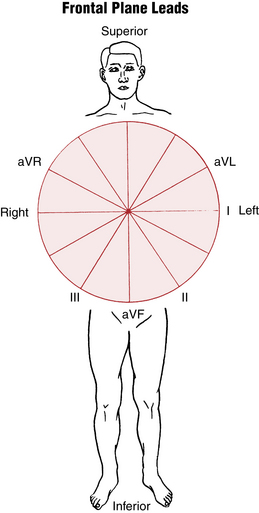
Specifically, the six limb leads (I, II, III, aVR, aVL, and aVF) record electrical voltages transmitted onto the frontal plane of the body (Fig. 3-10). (In contrast, the six precordial leads record voltages transmitted onto the horizontal plane.) For example, if you walk up to and face a large window, the window is parallel to the frontal plane of your body. Similarly, heart voltages directed upward and downward and to the right and left are recorded by the frontal plane leads.
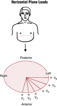
The six chest leads (V1 through V6) record heart voltages transmitted onto the horizontal plane of the body (Fig. 3-11). The horizontal plane cuts your body into an upper and a lower half. Similarly, the chest leads record heart voltages directed anteriorly (front) and posteriorly (back), and to the right and left.
Cardiac Monitors and Monitor Leads
Bedside Cardiac Monitors
Up to now, only the standard 12-lead ECG has been considered. However, it is not always necessary or feasible to record a full 12-lead ECG. For example, many patients require continuous monitoring for a prolonged period. In such cases, special cardiac monitors are used to give a continuous beat-to-beat record of cardiac activity from one monitor lead. Such ECG monitors are ubiquitous in emergency departments, intensive care units, operating rooms, and postoperative care units, as well in a variety of other inpatient settings.
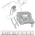
Figure 3-12 is a rhythm strip recorded from a monitor lead obtained by means of three disk electrodes on the chest wall. As shown in Figure 3-13, one electrode (the positive one) is usually pasted in the V1 position. The other two are placed near the right and left shoulders. One serves as the negative electrode and the other as the ground.

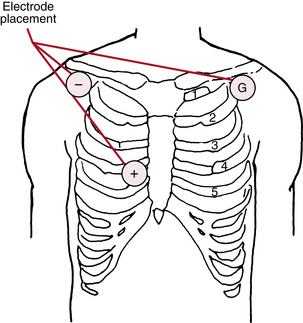
When the location of the electrodes on the chest wall is varied, the resultant ECG patterns also vary. In addition, if the polarity of the electrodes changes (e.g., the negative electrode is connected to the V1 position and the positive electrode to the right shoulder), the ECG shows a completely opposite pattern (see Fig. 3-12).
Ambulatory ECG Technology: Holter Monitors and Event Recorders
The cardiac monitors just described are useful in patients primarily confined to a bed or chair. Sometimes, however, the ECG needs to be recorded, usually to evaluate arrhythmias, in ambulatory patients over longer periods. A special portable system, designed in 1961 by N.J. Holter, records the continuous ECG of patients as they go about their daily activities (Box 3-2).
BOX 3-2 Advantages and Disadvantages of 24-Hour Holter Monitors
Advantages
• Useful for detecting very frequent, symptomatic arrhythmias.
• Useful for very accurate assessment of rate control in established atrial fibrillation.
• Useful for detecting ST segment deviations with “silent” ischemia or more rarely in making the diagnosis of Prinzmetal’s angina.
• Somewhat useful in detecting nocturnal arrhythmias (e.g., atrial fibrillation with sleep apnea).
• Useful for sustained monitoring during real-world strenuous activity (e.g., certain types of “in the field” sports, especially when a graded exercise test may be of limited use).
The limitations of Holter monitors have led to the development and widespread use of miniaturized ECG monitors, called event recorders. These event recorders are designed with replaceable electrodes so that patients can be monitored for prolonged periods (typically up to 2-3 weeks) as they go about their usual activities. The ECG is continuously recorded and then can be automatically erased unless the patient presses an event button (this type of event recorder is called a loop recorder).
Event recorders can also be used to monitor the ECG for asymptomatic drug effects and potentially important toxicities (e.g., excessive prolongation of the QT interval with drugs such as sotalol, quinidine, or dofetilide) or to detect other potentially proarrhythmic effects (Chapter 19) of drugs.
∗ This rule is only approximate. It is exact when the three standard limb leads are recorded simultaneously, using a three-channel electrocardiograph, because the peaks of the R waves in the three leads do not occur simultaneously. The exact rule is as follows: The voltage at the peak of the R wave (or at any point) in lead II equals the sum of the voltages in leads I and III at points occurring simultaneously.
∗ Although so-called unipolar leads (like bipolar leads) are represented by axes with positive and negative poles, the historical term unipolar does not refer to these poles; rather it refers to the fact that unipolar leads record the voltage in one locations relative to an electrodes (or set of electrodes) with close to zero potential.
† Augmentation was developed to make the complexes more readable.
∗ Sometimes, in special circumstances (e.g., a patient with suspected right ventricular infarction or congenital heart disease), additional leads are placed on the right side of the chest. For example, lead V3R is equivalent to lead V3, but the electrode is placed to the right of the sternum.