Chapter 154 Disc Replacement Technologies in the Cervical and Lumbar Spine
Background Considerations
The intervertebral disc is composed of a central nucleus pulposus (containing predominantly Type 1 collagen fibrils) and a peripheral annulus fibrosis (which can consist of up to 25 lamellae of mostly Type 1 collagen) that provides support, allows some movement, resists excessive movement, and, according to some absorbs shock.1 The ability to resist axial stresses is considerable but decreases with age.2 With normal loading, the normal nucleus pulposus is transposed by vertebral body pressure to tighten the annulus and produce ligamentous intervertebral stability. With heavy loading, the rigid, spherical normal nucleus pulposus gains stable seating in the nuclear recesses, where it acts as a piston to depress the cribriform plates, bend the trabeculae, and produce the necessary stability. With return of normal loading, the vertebral body rebounds, the nucleus pulposus resumes its normal locus, and the annulus tightens. Therefore it has been recognized that the vertebral bodies are very significant contributors to the shock-absorption function of the spinal column.3
It is fairly well accepted that the degenerative changes that result from aging of the vertebral body, the annulus fibrosis, and the nucleus pulposus are likely to begin with infarction of the cribriform cartilage endplates and subsequent nutritional failure of the nucleus pulposus.4 Calcification of the endplates occurs in adulthood, and the nutrient uptake and waste elimination within the disc then becomes dependent on diffusion. This leads to anaerobic metabolism’s taking a more prominent role, leading to lactate production and an acidic environment. The proteinases become more active, resulting in further disc degeneration.5 Indeed, it has been shown that when heavy loads are applied to the intervertebral disc, the normal disc biology can be disrupted, leading to an increase in catabolic enzymes and an acceleration of intervertebral disc degeneration.6 Studies have noted increased rates of degenerative disc disease in siblings of affected persons and strong correlation in twins.
The pathophysiology of the degenerative disease process has been described by Kirkaldy-Willis.7 The progressive disease is divided into three stages based on the amount of damage or degeneration to the disc and facet joints at a given point in time. However, the cascade of individual motion segment degeneration is best thought of as a continuous process rather than as three clearly definable and separate stages.
Stage 2: Instability
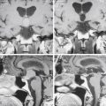
The second stage is described as the instability stage. It represents more significant tissue damage and tends to occur later in life, typically between 30 and 50 years of age. Multiple annular tears and delamination of the annulus fibrosis accelerates the intervertebral disc degeneration to a point where vertebral segment instability occurs. This results in a further decline in the nuclear proteoglycan composition, with a further resulting deterioration in the water content. Collapse of the nucleus pulposus leads to increased force transfer to the annulus fibrosis. The clinical episodes now tend to be periods of back pain that are usually more intense, often last longer, and tend to require more aggressive intervention. The MRI reveals loss of intervertebral disc height, a darker disc on T2-weighted imaging, and sometimes a disc herniation.
Stage 3: Stabilization
However, MRI is positive in asymptomatic patients at least 40% of the time.8–14 About 30% of adults without low back pain have evidence of protruded disc on MRI; more than half have bulging or degenerative discs and a fifth have annular fissures.15 Therefore, the relationship among disc degeneration, the MRI appearance, and spine-related pain remains controversial, and the decision to undertake surgical management of a degenerative spinal condition is a large one and is very much patient specific. The presurgical workup must include a thorough history relating to any spinal complaints including neurologic compromise, a diligent physical examination that leads to a working diagnosis, and the appropriate subsequent confirmatory radiologic imaging. Although simple radiography is an inexpensive and readily accessible starting point, its utility is severely limited by its inability to visualize neural structures directly or indirectly, and therefore the presence or absence of neural compression is indeterminable.16,17 Nonetheless, all our potential arthroplasty patients undergo plain flexion-extension radiographs of the appropriate spinal segment to look for instability of the potential operative or another segment and to confirm that there is still movement of the proposed operative segment. Also, if there is going to be any delay in obtaining true confirmatory imaging, routine spinal radiography should be undertaken to exclude other disease processes, such as malignancy, infection, or arthritis. Interestingly, when Friedenberg and Miller compared 92 asymptomatic patients with those complaining of neck and arm pain, no difference was found between the two groups in radiographic findings, with the exception of a greater incidence of disc degeneration at C5–6 and at C6–7 in the symptomatic group.18
None of our groups have been provided with the resources to undertake psychological profiling of prospective patients.19 Nonetheless, we try to avoid operating on patients with outstanding litigation claims.
General Considerations
The elimination of motion at the functional spinal unit (two vertebral bodies, the intervertebral disc, and associated facet joints) has been the mainstay of treatment since the 1960s.26 Anterior cervical discectomy and fusion is the standard of care for relief of pain and stabilization associated with radiculopathy and myelopathy,27 with excellent long-term results. However, lest we forget, very satisfactory results have been reported with the placement of nothing at all in the disc space after anterior cervical discectomy.28,29 It was the significant concerns raised by Hillibrand30,31 and others who noted, in various series of patients who had undergone anterior cervical arthrodesis, that between 25% and 89% who were followed for a lengthy period developed new degenerative changes at adjacent levels.
The debate is complex because much of the biomechanical and clinical evidence about the cause of adjacent segment disease is anecdotal and inconsistent.32 Although intradiscal pressure and motion alterations have been found at the adjacent levels following a single-level anterior lumbar interbody fusion (ALIF) in a calf model,33 it is recognized that longer fusions, both in the lumbar spine and in the cervical spine, have not been associated with higher rates of adjacent segment disease.32,34
Indeed, the recent enthusiasm for the application of cervical plates to aid fusion might actually be related to the increase in adjacent segment degeneration. Anterior plate impingement upon an adjacent disc is likely to accelerate adjacent level changes.35 An association between adjacent level ossification and the plate-to-disc distance has been established in a retrospective review of 118 patients undergoing anterior cervical discectomy and fusion.34 We should not forget that a patient who has already developed cervical spondylosis at the most common level (C5–6) to such a degree that surgery is warranted may be predisposed to develop degeneration at an adjacent level (C6–7 or C4–5) because of the natural history of the spondylosis and independent of whether or not a fusion is performed at the original level.
Moreover, despite the frequent reference to Hillibrand’s paper30 by those promoting arthroplasty, the authors later indicated that the paper suggested that the development of adjacent segment disease may be related to the natural history of cervical spondylosis.31 Similar findings have been documented in the lumbar spine by Ghiselli and colleagues,33 who found no correlation between the length of fusion and the rate of reoperation in 215 patients following posterior lumbar fusion. They noted that segments that were adjacent to a single-level fusion had a three times higher risk for developing disease than did those adjacent to a multiple-level fusion.
Operative Procedure
ProDisc-C Artificial Cervical Disc Placement
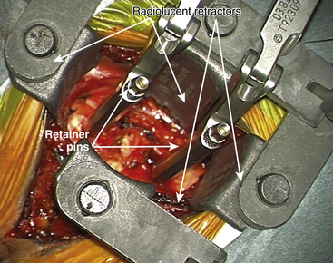
For placement of the implant it is essential to have radiolucent retractors because the procedure require visualization of most steps on x-ray.
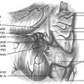
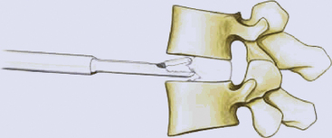
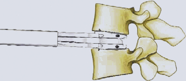
The ProDisc-C artificial cervical disc system comes with vertebral body retainer screws. The retainer screws are inserted under x-ray guidance (lateral projection) in the upper one third of the superior vertebra and inferior one third of the inferior vertebra parallel to the respective end plates (Fig. 154-1). The screws are bicortical. The length of the screws can be calculated on the picture archiving and communication system (PACS) using a CT scan image. The retainer handle is mounted onto the screws. It is important to leave enough space between the retainer pins to allow for the height of the keel on the ProDisc-C prosthesis. It is important not to use the retainer pins to distract the disc space. Their purpose is to stabilize the segment while the various steps of preparing the bed for the implant, keel cutting, and insertion of the implant are carried out.
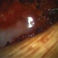
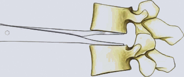
The primary objective of the operation is the decompression of the spinal canal and/or foramina. The annulus is incised and removed with a pituitary rongeur or curette. The disc can be removed with curettes or a high speed drill (Fig. 154-2). Good lateral exposure is necessary for the implant, and the dissection is continued laterally until the upslope of the uncovertebral joints on either side is identified. Further lateral dissection or drilling can damage the vertebral arteries. The uncovertebral joints must not be drilled to keep the segment stable after the insertion of the ProDisc-C implant.
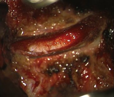
FIGURE 154-2 The posterior longitudinal ligament is excised and posterior osteophytes are removed.
(Courtesy of Mr. A. Saxena.)
Connect the trial handle to the trial implant. Ensure that the stop is fully screwed, closest to the footprint. Align the trail implant on the midline and advance the trial implant under image intensifier into the disc space.
Milling for Keel Cut Preparation
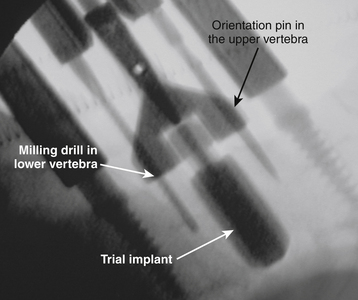
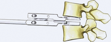
Choose the milling guide according to the height of the trial implant (Fig. 154-3). Slide the milling guide over the shaft of the trial implant and tighten the locking nut. Verify that the milling guide is centered on the midline. To ensure construct stability, place the sharp orientation pin through the superior hole in the milling guide and manually drive it into the bone under fluoroscopy control (Fig. 154-4).
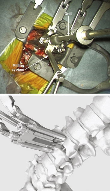
FIGURE 154-3 The trial implant is inserted under x-ray control. The milling system is loaded onto the trial implant.
(A and B courtesy of Mr. A. Saxena.)
Remove the milling bit and insert the blunt orientation pin into the inferior hole of the milling guide. Remove the sharp pin and repeat the milling procedure in the superior vertebral body. Ensure that the superior keel cut has the same distance to the posterior border of the vertebra as the inferior keel cut. If the superior keel cut has to be deepened, a special longer milling bit can be used.
Inserting the Implant
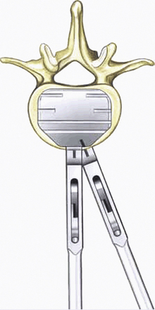
Align the keels of the ProDisc-C with the keel cuts. Ensure that the inferior plate with the inlay is caudal. Under lateral image intensifier fluoroscopic control, advance the ProDisc-C implant to the posterior margin of the vertebral bodies (Fig. 154-5). Release the implant inserter from the implant by opening the scissors and remove it by pulling it straight back out of the operative field. The surgeon ensures that the implant sits properly in the disc space. Step by step, remove the securing nuts, the vertebral body retainer, and the retainer screws.
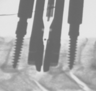
FIGURE 154-5 The implant is gently hammered into the disc space under x-ray control.
(Courtesy of Mr. A. Saxena.)
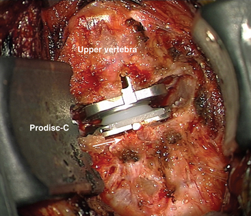
Once the artificial disc implant is disengaged from the disc inserter, the vertebral body distraction is released and the final position of the implant is checked visually and with fluoroscopy (Fig. 154-6). Appropriate sizing is critical to enhance motion, and overstuffing must be avoided.
Complications and Avoidance
Recurrent laryngeal nerve injury is another cause of postoperative hoarseness that may be permanent and cause some disability. Flynn reported its occurrence to be 1.4% of all cases.36 Recurrent laryngeal injury composed 17% of all neurologic complications in his large review. He noted that it often resulted in litigation. We do not routinely dissect out the recurrent laryngeal nerve on the right side, and in several hundred cases we have not found laryngeal nerve palsy to be a particular problem. More serious neurologic deficit occurs approximately once in every 355 cases (0.3%). Flynn noted that despite the cause of new-onset postoperative myelopathy, reoperation can have little influence on the ultimate status of the neurologic deficit. Moreover, Flynn suggested that most of the surgeons whose patients experienced myelopathic complications were unable to determine the cause.
Lumbar Arthroplasty
Certain criteria should be considered before offering such a procedure to the patient.
• In men or women a Visual Analog Score (VAS) less than 4, an Oswestry Disability Index (ODI) score greater than 40%
• Age between 18 and 60 years but optimally younger than 50 years
• Symptomatic degenerative disc disease or lumbar spondylosis with objective evidence of degenerative disease on MRI, which may include37:
The MRI characteristics as described by Kirkaldy-Wilis7 should also be reviewed. CT scans should be used to exclude osteoarthritis of the facet (zygapophyseal) joints, Baastrup’s disease (kissing spines), and other sources of back pain. Fugiwara and colleagues have developed a grading system describing facet joint degeneration.38 A preoperative CT scan is invaluable in obtaining measurements of the vertebral body size parameters in preparation for arthroplasty. Bertagnoli and Kumar have emphasized the importance of facet joint assessment.39 We prefer to use diagnostic facet joint injections and discography in patients in whom other potential sources of pain exist. However, it is imperative to remember that discography is just one aid to diagnosis. It does not of itself define the need for surgical intervention or otherwise. The discographic findings should complement the history, examination, and other investigation findings. If osteoporosis is suspected, a DEXA (dual-energy x-ray absorptiometry) scan is usually requested.
Radiographically, patients with at least 50% remaining disc height obtain higher satisfaction rates compared to those with less than 50%, especially when discography is complementary. In our experience, patients with greater disc heights generally appear to experience greater and more consistent relief of their symptoms.
Definite contraindications and relative contraindications to lumbar arthroplasty exist. The presence of spondylolysis, spondylolisthesis, spinal fracture, posterior element disease such as a significant facet joint arthropathy or previous facet joint removal (from posterior surgery), central or lateral recess stenosis, herniated nucleus pulposus with a radiculopathy, a nonmobile segment, osteoporosis, or infection should be considered to be contraindications to an arthroplasty. Issues such as obesity and psychosocial conditions should be considered. Some commentators consider the prevalence of contraindications—either absolute or relative—to lumbar arthroplasty to be very high.40 Again, satisfactory alternatives to arthroplasty exist, and in lumbar fusion procedures the risk of same-level disease is limited to patients who develop a pseudarthrosis. With an arthroplasty, however, there is a risk of causing new problems at the same level, particularly at the facet joints or ligamentum flavum. Despite the advanced biomechanical properties of the latest arthroplasty devices, they do not reproduce the movements of a normal healthy spinal motion segment with its constantly changing centre of rotation and complex coupled motions. These new abnormal forces can place new abnormal stresses on the facet joints and intervertebral ligaments, with resultant strains and pathologic degeneration.
Another interesting challenge to the implantation of a lumbar artificial disc replacement can be the variable contour morphology of the vertebral end plate, as described by the Yue-Bertagnoli classification (Fig. 154-7).
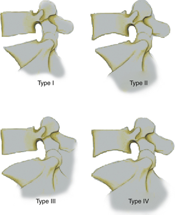
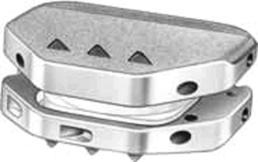
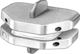
Flat end plates make implantation easier. End plates that exhibit a type II or type III morphology require, respectively, either a keel or a spike mode of endplate stabilization (Figs. 154-8 and 154-9). An implant that offers this type of anatomically adaptive solution enables the surgeon to provide artificial disc replacement surgery to patients who would otherwise have been excluded.
Exposing the Anterior Lumbar Spine
Exposure of the anterior portion of the lumbar disc can be obtained through either a transperitoneal or retroperitoneal approach using various skin incisions.41–43 We tend to use a retroperitoneal approach, when possible, because it obviates the need for bowel retraction. Transperitoneal approaches can carry a considerably higher risk of complications, including postoperative ileus or injury to the presacral plexus.
Before marking, lateral and AP fluoroscopic x-rays are obtained to identify the disc space relative to the potential skin incision (Fig. 154-10). We place the patient in a supine position with slightly flexed hips to relieve tension from the major blood vessels.
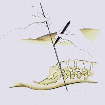
FIGURE 154-10 To mark the incision, a lateral radiograph is taken, with a metal rod parallel to the defective disc.
A right side approach is recommended for the L5–S1 level and a left side approach for higher levels.
The operating table should permit image intensifier images in two planes in the operating zone.
Marking the Approach
To mark the incision, a lateral image is taken, with a metal rod parallel to the defective disc compartment. The extension of this marking corresponds to the midpoint of the skin incision (see Fig. 154-10).
Mobilizing Blood Vessels
The aorta and its branches and the inferior vena cava and its tributaries lie anterior to the lumbar vertebral column. The aorta usually divides into the common iliac arteries at the level of upper L5 just on the left side of the vertebral body. The middle sacral artery arises from the posterior aspect of the aorta and descends roughly in the midline along the L5 and S1 vertebrae. The right common iliac, longer than the left, passes obliquely across the body of L5. The arteries are separated from the vertebra by the deeper common iliac veins and inferior vena cava and by some fibrocartilage. The right iliac arteries are just medial to the inferior vena cava and the right common iliac vein. The left common iliac vein lies partly medial to and partly behind (deep to) the left iliac arteries. The common iliac veins coalesce at a relatively acute angle over the L5 vertebral body to form the inferior vena cava. The left common iliac vein courses initially on the medial aspect of the left iliac artery and then runs behind the right common iliac artery. Each common iliac vein receives an ileolumbar vein and sometimes a lateral sacral vein. The left common iliac vein drains the middle sacral vein. Although this outline represents a standard description, variations and anomalies are not uncommon.44
It is usually reasonably straightforward to expose the L5–S1 disc space by dissecting between the iliac vessels to expose the sacral promontory. The common iliac vessels are mobilized laterally and the middle sacral vessels can be safely divided to provide adequate exposure of the disc space. Blunt dissection is usually then satisfactory.
However, to expose a disc higher than L5–S1 it is necessary to mobilize the overlying aorta and inferior vena cava medially. Because the bifurcation of the aorta and the inferior vena cava is usually below the L4 vertebral body, it is usually not possible (and in general should not be attempted) to approach the L4–5 disc between the iliac vessels. There is a real risk either of causing a thrombosis of the iliac arteries or iliac veins or, indeed, of actually tearing a vessel owing to excessive retraction. Therefore the safest approach to the L4–5 lumbar disc is to identify the ileolumbar vein, which often drains into the left lateral common iliac vein, and ligate and divide it. The L5 nerve root often runs in close proximity to the ileolumbar vein as it heads to join the lumbosacral plexus. It should be identified and protected and avoided. Major vein lacerations have been reported to occur in between 1.4% and 3% of cases, although the unreported incidence may be considerably higher.45,46 It is wise to use only bipolar diathermy or electrocautery to avoid inadvertent damage that may occur with monopolar diathermy. If retroperitoneal lymphatics are seen to be damaged they should be ligated.
The ureter normally is swept off the psoas muscle with the peritoneum. Nonetheless care should be taken to be certain of its location to ensure that it is not inadvertently injured. Injury to the superior hypogastric plexus can result in retrograde ejaculation, which has been reported to occur between in between 0.42% and 6% of cases.47,48 This nerve plexus is usually located in the retroperitoneal space in close proximity to the lumbosacral junction and overlies the origin of the common iliac artery, making it vulnerable to injury during dissection and mobilization. Dissection in the retroperitoneal approach tends to mobilize the plexus.
Discectomy and Preparing the Endplate
A discectomy is performed and the endplates are cleared of residual disc with a variety of different-sized curettes and rongeurs (Fig. 154-11). The soft disc components should be carefully removed to preserve the bony endplates. The cartilaginous endplate should be removed as completely as possible. Cartilaginous material can impede osteointegration of the Plasmapore μ-CaP coating of the implant to the endplates. However, too-extensive preparation and thinning of the bony endplates can increase the risk of implant subsidence and migration.
The mobilization of the interspace should be performed using interspace distractors and verified using trials and lateral fluoroscopy (Fig. 154-12). The angled distractor provides a better view into the operating site and facilitates the discectomy and preparation of endplates.
We verify the size of the trial implant in the disc compartment by fluoroscopy (Fig. 154-13). An oversized implant can lead to overdistraction, which can irritate the facets, nerve roots, or contents of the thecal sac. An undersized inlay can result in the implant’s sitting too loosely in the degenerated disc compartment, which can lead to instability or implant migration.
The implant is mounted with the defined angle and size onto the parallel distracter (Fig. 154-14). The position and correct placement of the implant is confirmed with the image intensifier (Fig. 154-15).
Closure
The H-shaped annular flaps are sutured. An appropriate fascial and skin closure is performed.
Postoperative Care
We advise that patients should be restricted from overusing their abdominal muscles for 8 weeks to protect the fascial closure. Patients should receive prophylactic intravenous antibiotics for 24 to 48 hours following surgery. Deep vein thrombosis (DVT) prophylaxis is undertaken using a sequential leg compression device along with subcutaneous enoxaparin.
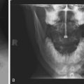
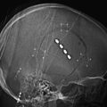
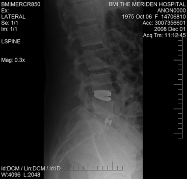
Radiographic imaging confirming satisfactory placement is obtained before hospital discharge (Fig. 154-16).
Complications and Avoidance
We have reviewed the results of our first 37 patients in whom an Active L artificial disc prosthesis was implanted. There were 18 men with average age of 46 years (range, 37 to 58 years) and 19 women with an average age of 38 years (range, 30 to 49 years). Seventeen prostheses were implanted at the L5–S1 level and 20 at the L4–5 level. In five of these latter patients an anterior intervertebral fusion (stand-alone ALIF) was performed additionally at the L5–S1 level. The indications included monosegmental disk degeneration in 32 cases, bisegmental disk degeneration in 5 cases, and a postdiscectomy syndrome in 6 cases. The range of follow-up time varies from 3 months to 2 years. The Oswestry Disability Index (ODI), Visual Analogue Score (VAS), and Short-Form 36 (SF-36) questionnaires were used for clinical evaluation. Twenty-six patients enjoyed an excellent result; nine enjoy a good to fair result. Two patients have required further surgery for increased facet joint pain.
Boden S., Davis D., Dina T., et al. Abnormal magnetic-resonance scans of the lumbar spine in asymptomatic subjects. A prospective investigation. J Bone Joint Surgery Am. 1990;72:403-408.
Bohlmann H., Emery S., Goodfellow D., Jones P. Robinson anterior cervical discectomy and arthrodesis for cervical radiculopathy. Long-term follow up of one hundred and twenty two patients. J Bone Joint Surg Am. 1994;75:1298-1307.
Borenstein D., O’Mara J., Boden S., et al. The value of magnetic resonance imaging of the lumbar spine to predict low-back pain in asymptomatic subjects: a seven year follow-up study. J bone Joint Surg Am. 2001;83:1306-1311.
Chitnavis B., Barbagallo G., Selway R., et al. Posterior lumbar interbody fusion for revision disc surgery: review of 50 cases in which carbon fibre cages were implanted. J Neurosurg. 2001;95:190-195.
Cloward R. The anterior approach for removal of ruptured discs. J Neurosurg. 1958;15:602-614.
Elfering A., Semmer N., Birkhofer D., et al. Risk factors for lumbar disc degeneration: a five year prospective MRI study in asymptomatic individuals. Spine. 2002;27:125-134.
Emery S., Bohlmann H., Bolesta M., Jones P. Anterior cervical decompression and arthrodesis for treatment of cervical spondylotic myelopathy. Two- to seventeen-year follow-up. J Bone Joint Surg Am. 1998;80:941-951.
Erkintalo M., Salminen J., Alamen A., et al. Development of degenerative changes in the lumbar intervertebral disc: results of a prospective MR Imaging study in adolescents with and without low back pain. Radiology. 1995;196(2):529-533.
Flynn T.B. Neurological complications of anterior cervical interbody fusion. Spine. 1982;7:536-539.
Hillibrand A., Carlson G., Palumbo, et al. Radiculopathy and myelopathy at segments adjacent to the site of a previous arthrodesis. J Bone Joint Surg Am. 1999;81:519-528.
Huang R.C., Lim M.R., Girardi F.P., et al. The prevalence of contra indications to total disc replacement in a cohort of lumbar surgical patients. Spine. 2004;29:2538-2541.
Jensen M., Bront-Zawadzki M., Obuchowski N., et al. Magnetic resonance imaging of the lumbar spine in people without back pain. NEng J Med. 1994;331:69-73.
Martins A. Anterior cervical discectomy with and without interbody bone graft. J Neurosurg. 1996;44:290-295.
McKenzie A. The basis for motion preservation surgery: lessons learned from the past. In: Yue J., Bertagnoli R., McAfee P., An H. Motion Preservation Surgery of the Spine. Advanced Techniques and Controversies. St. Louis: Saunders, 2008., p. 3
Smith G., Robertson R. The treatment of certain cervical spine disorders by anterior removal of the intervertebral disc and interbody fusion. J Bone Joint Surg Am. 1958;40:607-623.
Sumpio B., Gumbs A. Revision open anterior approach for spine procedures. Spine J. 2006;7:280-285.
Tinsman H., Seitsalo D., Osterman K., Soini J. Retrograde ejaculation after anterior interbody fusion. Eur Spine J. 1995;4:339-342.
White A.A., Panjabi M.M. The basic kinematics of the human spine: a review of past and current knowledge. Spine. 1978;3:12-20.
Yong-Hing K., Kirkaldy-Willis W.H. The pathophysiology of degenerative disease of the lumbar spine. Orthop Clin North Am. 1983;3:491-504.
1. Benzel E. Biomechanics of spine stabilization. Rolling Meadows, IL: American Association of Neurological Surgeons; 2001., p. 7
2. White A.A., Panjabi M.M. The basic kinematics of the human spine: a review of past and current knowledge. Spine. 1978;3:12-20.
3. McKenzie A. The basis for motion preservation surgery: lessons learned from the past. In: Yue J., Bertagnoli R., McAfee P., An H. Motion Preservation Surgery of the Spine. Advanced Techniques and Controversies. St. Louis: Saunders, 2008., p. 7
4. Schmorls G., Junghanns H. The Human Spine in Health and Disease, 2nd ed. New York: Grune & Stratton; 1971.
5. Ohshima H., Urban J.P. The effect of lactate and pH on proteoglycans and protein synthesis rates in the intervertebral disc. Spine. 1992;17:1079-1082.
6. Maclean J., Lee C., Grad S., et al. Effects of immobilisation and dynamic compression on the intervertebral disc cell gene expression in vivo. Spine. 2003;28:973-981.
7. Yong-Hing K., Kirkaldy-Willis W.H. The pathophysiology of degenerative disease of the lumbar spine. Orthop Clin North Am. 1983;3:491-504.
8. Quint D. Imaging of back pain. In: Haig A., Calwell M. Back Pain. Philadelphia: American College of Physicians, 2005., p. 199
9. Erkintalo M., Salminen J., Alamen A., et al. Development of degenerative changes in the lumbar intervertebral disc: results of a prospective MR Imaging study in adolescents with and without low back pain. Radiology. 1995;196(2):529-533.
10. Salminen J., Erkintalo M., Laine M., Penlti J. Low back pain in the young. A prospective three-year follow-up study of subjects with and without low back pain. Spine. 1995;20:2101-2107.
11. Savage R., Whitehouse G., Roberts N. The relationship between the magnetic resonance imaging appearance of the lumbar-spine and low back pain, age and occupation in males. Eur Spine J. 1997;6:106-114.
12. Jensen M., Bront-Zawadzki M., Obuchowski N., et al. Magnetic resonance imaging of the lumbar spine in people without back pain. NEng J Med. 1994;331:69-73.
13. Borenstein D., O’Mara J., Boden S., et al. The value of magnetic resonance imaging of the lumbar spine to predict low-back pain in asymptomatic subjects: a seven year follow-up study. J bone Joint Surg Am. 2001;83:1306-1311.
14. Boden S., Davis D., Dina T., et al. Abnormal magnetic-resonance scans of the lumbar spine in asymptomatic subjects. A prospective investigation. J Bone Joint Surgery Am. 1990;72:403-408.
15. Jarvik J., Deyo R. Diagnostic evaluation of low back pain with emphasis on imaging. Ann Intern Med. 2002;137:586-597.
16. Bell G., Ross J. Diagnosis of nerve root compression, myelography, computed tomography and MRI. Orthop Clin North Am. 1992;23:405-419.
17. Rahim K., Stambough J. Radiographic evaluation of the degenerative cervical spine: a comparative study of asymptomatic and symptomatic patients. J Bone Joint Surg Am. 1963;45:1171-1178.
18. Friedenberg Z., Miller W. Degenerative disc disease of the cervical spine: A comparative study of asymtomatic and symptomatic patients. J Bone Joint Surg (Am). 1963;45:1171-1178.
19. Kwon B., Vaccaro A., Grauer J., Beiner J. Indications, techniques, and outcomes of posterior surgery for chronic low back pain. Orthop Clin North Am. 2003;34:297-308.
20. Dardis R., Casey A., Lafuente J., Gullan R. Innovations in anterior cervical spine surgery. In: Schmidek H., Roberts D. Schmidek and Sweet Operative Neurosurgical Techniques. Philadelphia: Saunders, 2006., pp. 1833-1847
21. Brooke N., Rorke A., King A., Gullan R. Preliminary experience of the use of carbon fibre cage prosthesis for the treatment of cervical spine disorders. Br J Neurosurg. 1997;11:221-227.
22. Shad A., Leach J., Teddy P., Cadoux-Hudson T. Use of Solis cage and local autologous bone graft for anterior cervical discectomy and fusion: early technical experience. J Neurosurg Spine. 2005;2:116-122.
23. Chitnavis B., Barbagallo G., Selway R., et al. Posterior lumbar interbody fusion for revision disc surgery: review of 50 cases in which carbon fibre cages were implanted. J Neurosurg. 2001;95:190-195.
24. Cloward R. The anterior approach for removal of ruptured discs. J Neurosurg. 1958;15:602-614.
25. Smith G., Robertson R. The treatment of certain cervical spine disorders by anterior removal of the intervertebral disc and interbody fusion. J Bone Joint Surg Am. 1958;40:607-623.
26. Bohlmann H., Emery S., Goodfellow D., Jones P. Robinson anterior cervical discectomy and arthrodesis for cervical radiculopathy. Long-term follow up of one hundred and twenty two patients. J Bone Joint Surg Am. 1994;75:1298-1307.
27. Emery S., Bohlmann H., Bolesta M., Jones P. Anterior cervical decompression and arthrodesis for treatment of cervical spondylotic myelopathy. Two- to seventeen-year follow-up. J Bone Joint Surg Am. 1998;80:941-951.
28. Maurice-Williams R., Howard N. Extended anterior cervical discectomy without fusion: a simple and sufficient operation for most cases of cervical degenerative disease. Br J Neurosurg. 1996;10:261-266.
29. Martins A. Anterior cervical discectomy with and without interbody bone graft. J Neurosurg. 1996;44:290-295.
30. Hillibrand A., Carlson G., Palumbo, et al. Radiculopathy and myelopathy at segments adjacent to the site of a previous arthrodesis. J Bone Joint Surg Am. 1999;81:519-528.
31. White A., Hannallah D., Hilibrand A. Adjacent segment degeneration and adjacent segment disease: cervical and lumbar. In: Yue J.J., Bertagnoli R., McAfee P.C., An H.S. Motion Preservation Surgery of the Spine. Advanced Techniques and Controversies. St Louis: Elsevier, 2008., p. 118
32. Rao R.D., David K.S., Wang M. Biomechanical changes at adjacent segments following anterior lumbar interbody fusion using tapered cages. Spine. 2005;24:2772-2776.
33. Ghiselli G., Wang J.C., Bhatia N.N., et al. Adjacent segment degeneration in the lumbar spine. J Bone Joint Surg Am. 2004;86(7):1497-1503.
34. White A., Hannallah D., Hilibrand A. Adjacent segment degeneration and adjacent segment disease: cervical and lumbar. In: Yue J.J., Bertagnoli R., McAfee P.C., An H.S. Motion Preservation Surgery of the Spine. Advanced Techniques and Controversies. St Louis: Elsevier, 2008., p. 123
35. Park J., Cho Y., Riew D. Development of adjacent-level ossification in patients with anterior cervical plate. J Bone Joint Surg Am. 2005;87:558-563.
36. Flynn T.B. Neurological complications of anterior cervical interbody fusion. Spine. 1982;7:536-539.
37. Elfering A., Semmer N., Birkhofer D., et al. Risk factors for lumbar disc degeneration: a five year prospective MRI study in asymptomatic individuals. Spine. 2002;27:125-134.
38. Fujiwara A., Lim T.H., An H.S., et al. The effect of disc degeneration and facet joint osteoarthritis on the segmental flexibility of the lumbar spine. Spine. 2000;25:3036-3044.
39. Bertagnoli R., Kumar S. Indications for full prosthetic disc arthroplasty: a correlation of clinical outcome against a variety of indications. Eur Spine J. 2002;11:S131-S136.
40. Huang R.C., Lim M.R., Girardi F.P., et al. The prevalence of contra indications to total disc replacement in a cohort of lumbar surgical patients. Spine. 2004;29:2538-2541.
41. Gumbs A., Shah R., Yue J., Sumpio B.E. The open anterior paramedian retroperitoneal approach for spine procedures. Arch Surg. 2005;140:339-343.
42. Brau S., Delamarter R., Schiffman M., et al. Vascular injury during anterior lumbar surgery. Spine J. 2004;4:409-412.
43. Bianchi C., Ballard J., Abou-Zanzan A., et al. Anterior retroperitoneal lumbosacral spine exposure: operative techniques and results. Ann Vasc Surg. 2003;17:137-142.
44. Baniel J., Roster R., Donohue J. Surgical anatomy of the lumbar vessels: implications for retroperitoneal surgery. J Urol. 1995;153:1422-1424.
45. Sumpio B., Gumbs A. Revision open anterior approach for spine procedures. Spine J. 2006;7:280-285.
46. Brau S., Spoonamore M., Snyder L., et al. Nerve monitoring changes related to iliac artery compression driving anterior lumbar surgery. Spine J. 2003;3:351-355.
47. Tinsman H., Seitsalo D., Osterman K., Soini J. Retrograde ejaculation after anterior interbody fusion. Eur Spine J. 1995;4:339-342.
48. Sasso R., Kenneth Burkus J., Lethnec J. Retrograde ejaculation after anterior lumbar interbody fusion: transperitoneal versus retroperitoneal exposure. Spine J. 2003;28:1023-1026.