Chapter 13 Digital radiography
 Most hospitals within the UK are now completely film-less or in the process of replacing film with various digital systems.


INTRODUCTION
As with the recent developments with general photography, where digital cameras are replacing film, this technology is also being used to replace X-ray film with digital imaging. Digital imaging has already been in use for many years in computed tomography (CT), magnetic resonance imaging (MRI), nuclear medicine (NM), fluoroscopy and ultrasound, but only recently has conventional X-ray equipment started to use digital technology.
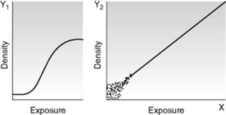
Digital radiography has greater exposure latitude than X-ray film; therefore any over- or underexposure of an image can still be viewed. However, there is a trade off between radiation dose and image quality, as high exposures will give a very clear image but an unacceptable dose to the patient. Low exposures will result in a noisy (grainy) image and may miss diagnostically significant information. This is an advantage over the traditional film–screen combination where any exposure in the foot or shoulder areas of the characteristic curve will result in no usable image being obtained (Fig. 13.1).
COMPUTED RADIOGRAPHY
THE IMAGING PLATE
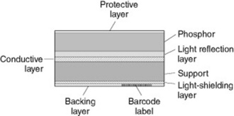
The imaging plate is coated with a photostimulable phosphor (PSP), which captures X-rays once they have passed through the patient or object being imaged (Fig. 13.2). The PSP material has been ‘doped’ with small amounts of impurities which alter the physical properties of its crystalline structure.
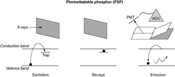
As the X-rays pass through the PSP material, they interact with the electrons in the crystalline structure, giving them energy, which enables them to enter the conduction band. Some electrons return immediately to the valence band, but others remain ‘trapped’ in the forbidden zone between the two bands (Fig. 13.3). This trapped signal is proportional to the amount of radiation incident on the plate; these electrons form the latent image in the PSP.
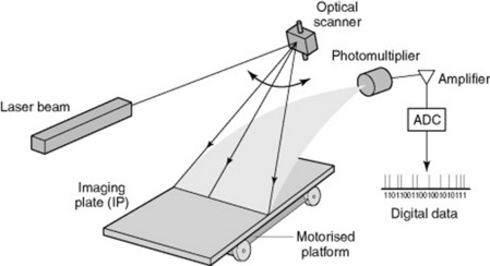
RETRIEVING THE LATENT IMAGE
To retrieve the latent image from the PSP it is placed in a CR reader, where a laser scans it (Fig. 13.4). The laser gives the electrons enough energy to return and leave the traps and to decay down to the ground or valence state. As these electrons move down in energy a blue light is emitted. This light is collected by a light guide and directed towards the photomultiplier tube. The light moves through the photomultiplier, is then amplified and then the signal is digitised using an analogue-to-digital converter, allowing the temporary storage of the image in digital format. This can then be sent to a monitor for viewing or to a printer.
CARE OF THE IMAGING PLATE AND CASSETTE
CR plates should be checked regularly for damage, as part of a departmental quality assurance programme, and removed from use or repaired if damage is found. The imaging plates also need regular checks because they are removed from the cassette each time they are read – edges tend to get damaged, cracks can appear and they can be vulnerable to scratches. Once again any damaged plates must be removed from service. There have been reported problems with cassette catches opening and the plates dropping out, so these must be checked and cleaned before being returned to service. Imaging plates have an estimated life of 10 000 exposures (manufacturer dependent), so it is important to make sure cassettes are rotated and used evenly throughout a department.
IMAGING THE PATIENT USING CR
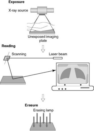
The patient is registered to each imaging plate used by means of an individual barcode on each plate, using the patients’ hospital number. X-rays are then taken, the operator inputs into the CR reader the views that have been taken (e.g. chest X-ray (CXR), abdominal X-ray (AXR)) and the plates are then placed in the CR reader, which picks up the barcode and allocates images to the correct patient, along with the correct protocol for image processing (Fig. 13.5).
The CR reader then removes the plate from the cassette and this is read out as previously described. The image is subsequently viewed on an acquisition workstation where it is cropped and markers applied (i.e. L or R, PA, AP, etc.). The image can be checked for quality and dose indicators, such as sensitivity or exposure index (manufacturer dependent). Once the radiographer is satisfied that the image is correctly identified, manipulated and annotated, it is then sent on to the network for reporting and storage for retrieval at a later date from anywhere within the network (Fig. 13.6).
DIGITAL RADIOGRAPHY
Currently there are two types of system utilised for digital imaging:
INDIRECT DIGITAL RADIOGRAPHY
Indirect digital radiography (IDR) uses a phosphor (caesium iodine, CsI), which is coated over an active matrix array (AMA) of amorphous silicon (a-Si) (Fig. 13.7).
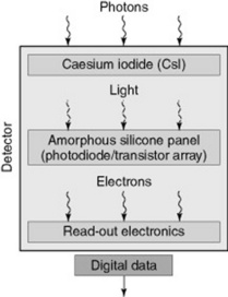
Image production
DIRECT DIGITAL RADIOGRAPHY
Direct digital radiography (DDR) does not use a phosphor material; the X-ray photons are directly converted into an electrical charge. The detector material used is amorphous selenium (a-Se) which is coated on a thin-film-transistor (TFT) array (Fig. 13.8).
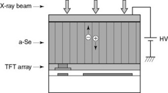
A bias voltage is applied across the detector structure and as the X-rays pass through they directly generate positive and negative charges which are in proportion to the level of X-ray exposure. The positive charge is drawn to the capacitor where it is stored and readout by the customised electronics within the array. The imaging plate is made up from millions of these detectors causing variations between them. Software is available to smooth out the differences between the detectors on the plate. This smoothing process is known as ‘stitching’. As with CR, the patient images are checked, annotated and sent onto the computer network for reporting and storage.
PACS – PICTURE ARCHIVING AND COMMUNICATIONS SYSTEM
PACS is the system predominately used for the image acquisition, image display, the network and storage and retrieval of images in most hospitals and clinical environments. Implementation of PACS has become widespread and has resulted in the use of softcopy display for reporting and display (Fig. 13.9).
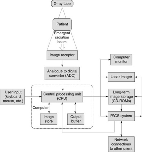
Figure 13.9 Typical set-up of a picture archiving and communications system (PACS) in the clinical environment.
IMAGE DISPLAY
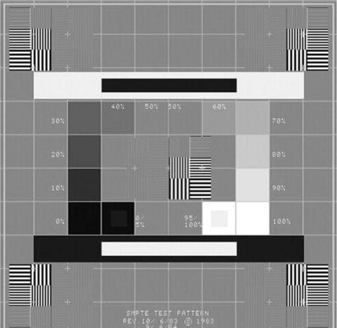
The reporting monitors must be checked daily using a recognised test pattern such as the SMPTE test pattern (Fig. 13.10). There should be checks for distortion and centring, by verifying that all 11 luminance patches are visible. It should be checked that the 5% and 95% patches can be seen and the visibility of the high and low contrast line pair patterns should be assessed.