Digital Imaging Characteristics
Objectives
On completion of this chapter, you should be able to:
• Differentiate between analog and digital images.
• Define pixel and image matrix and characteristics of each.
• Relate pixel size, matrix size, and field of view (FOV) to each other.
• Discriminate between standard units of measure for exposure indicators.
• Discuss the differences between spatial resolution and contrast resolution.
Key Terms
Air kerma
Analog
Brightness
Contrast resolution
Detective quantum efficiency (DQE)
Deviation index (DI)
Digital
Dynamic range
Field of view (FOV)
Indicated equivalent air kerma (KIND)
Latitude
Matrix
Modulation transfer function (MTF)
Noise
Noise power spectrum (NPS)
Pixel
Pixel bit depth
Signal-to-noise ratio (SNR)
Spatial resolution
Standardized radiation exposure (KSTD)
Target equivalent air kerma value (KTGT)
In medical imaging, there are two types of images: analog and digital. Analog images are those types of images that are very familiar to us, such as paintings and printed photographs. What we are seeing in these images are the various levels of brightness and colors; the images are continuous; that is, they are not broken into their individual pieces. Digital images are recorded as multiple numeric values and are divided into an array of small elements that can be processed in many different ways.
Analog Images Versus Digital Images
When we talk about digitizing a signal from a digital radiographic unit, we are talking about assigning a numerical value to each signal point, either an electrical impulse or a light photon. As humans, we experience the world through analog vision. We see our surroundings as infinitely smooth gradients of shapes and colors. Analog refers to a device or system that captures or measures a continuously changing signal. In other words, the analog signal wave is recorded or used in its original form. A typical analog device is a watch in which the hands move continuously around the face and is capable of indicating every possible time of day. In contrast, a digital clock is capable of representing only a finite number of times (every tenth of a second, for example).
Traditionally, radiographic images were formed in an analog fashion. A cassette, containing fluorescent screens and film sensitive to the light produced by the screens, is exposed to radiation and then processed in chemical solutions. Today, images can be produced through a digital system that uses detectors to convert the x-ray beam into a digital image.
In an analog system such as film/screen radiography, x-ray energy is converted to light, and the light waves are recorded just as they are. In digital radiography, analog signals are converted into numbers that are recorded. Digital images are formed through multiple samplings of the signal rather than the one single exposure of an analog image.
Characteristics of a Digital Image
A digital image begins as an analog signal. Through computer data processing, the image becomes digitized and is sampled multiple times. The critical characteristics of a digital image are spatial resolution, contrast resolution, noise, and dose efficiency (of the receptor); however, to fully grasp how a digital image is formed, an understanding of its basic components is necessary.
Pixel
A pixel, or picture element, is the smallest element in a digital image. If you have ever magnified a digital picture to the point that you see the image as small squares of color, you have seen pixels (Figure 2-1).
Spatially, the digital image is separated into pixels, with discrete (whole numbers only) values. The process of associating the pixels with discrete values defines maximum contrast resolution.
Pixel Size.
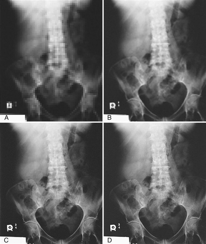
The size of the pixel is directly related to the amount of spatial resolution or detail in the image. For example, the smaller the pixel is, the greater the detail. Pixel size may change when the size of the matrix or the FOV changes.
Pixel Bit Depth.
Each pixel contains pieces or bits of information. The number of bits within a pixel is known as pixel bit depth. If a pixel has a bit depth of 8, then the number of gray tones that pixel can produce is 2 to the power of the bit depth, or 28 or 256 shades of gray. Some digital systems have bit depths of 10 to 16, resulting in more shades of gray. Each pixel can have a gray level between 1 (20) and 65,536 (216). The gray level will be a factor in determining the image contrast resolution.
Matrix
A matrix is a square arrangement of numbers in columns and rows, and in digital imaging, the numbers correspond to discrete pixel values. Each box within the matrix also corresponds to a specific location in the image and corresponds to a specific area of the patient’s tissue. The image is digitized both by position (spatial location) and by intensity (gray level). The typical number of pixels in a matrix ranges from about 512 × 512 to 1024 × 1024 and can be as large as 2500 × 2500. The size of the matrix determines the size of the pixels. For example, if you have a 10 × 12 and a 14 × 17 computed radiography (CR) cassette and both have a 512 × 512 matrix, then the 10 × 12 cassette will have smaller pixels.
Field of View
The term field of view, or FOV, is synonymous with the x-ray field. In other words, it is the amount of body part or patient included in the image. The larger the FOV, the more area is imaged. Changes in the FOV will not affect the size of the matrix; however, changes in the matrix will affect pixel size. This is because as the matrix increases (e.g., from 512 × 512 to 1024 × 1024) and the FOV remains the same size, the pixel size must decrease to fit into the matrix (Figure 2-2).
Pixel Size, Matrix Size, and FOV
A relationship may exist between the size of the pixel, the size of the matrix, and the FOV. The matrix size can be changed without affecting the FOV and the FOV can be changed without affecting the matrix size, but a change in either the matrix size and/or the FOV changes the size of the pixels.
Exposure Indicators
The exposure index refers to the amount of exposure received by the image receptor (IR), not by the patient. However, knowing how exposure factors affect the exposure index is key to learning to provide enough exposure to the receptor while limiting exposure to the patient. Because manufacturers differ in the way exposure is numerically represented, it can be difficult to calculate exposure amounts. The clinical world has been calling for exposure indicator standardization for several years. In 2008 the International Electrotechnical Commission (IEC) published a report titled “Medical Electrical Equipment—Exposure Index of Digital X-Ray Imaging Systems—Part 1: Definitions and Requirements for General Radiography,” and in 2009 the American Association of Physicists in Medicine (AAPM) released its “An Exposure Indicator for Digital Radiography” report. The AAPM report expressed the clinical need to have this standardization, saying that standardization will give the technologist more confidence in adjusting technical factors while following the ALARA (as low as reasonably achievable) principle. The following paragraphs explain some of the most important terms that came from this research. Further information may be gained about this standardization effort by downloading the AAPM report (No. 116) from the AAPM website. For information on proprietary exposure indices, either contact the vendor directly or consult the equipment manual for specific information.
Standard Units of Measure
Standardized Radiation Exposure (KSTD).
Before the standard radiation exposure is explained, let’s first revisit a few radiation units. Air kerma (kinetic energy released per unit mass [of air]) is the measurement of radiation energy (joules or J) absorbed in a unit of air (kg). Therefore the quantity kerma is expressed as J/kg or gray (Gy). The gray will be used most often in equipment to express this measurement. When an exposure is made of an IR, the air kerma can be easily read during the processing of the exposure.
The standardized radiation exposure (KSTD) is a standard exposure typical of that imaging receptor system. The exposure is made with additional filtration that hardens the beam to simulate patient tissue. These standard conditions for the exposure are used to ensure that the equipment is functioning appropriately.
Indicated Equivalent Air Kerma (KIND).
The indicated equivalent air kerma (KIND) is the measurement of the radiation that was incident on the IR for that particular exposure. This measurement is derived from reading the pixel values produced by the exposure on an IR. These values are known as for-processing pixel values (Q), and the median is found after certain data correction has taken place and the median value is then compared to the KSTD exposure to derive the KIND. This may seem complicated, but the KIND can be simply stated as the amount of exposure on the IR. This value will help determine whether the IR has been overexposed or underexposed for that particular body part.
Target Equivalent Air Kerma Value (KTGT).
The target equivalent air kerma value (KTGT) is a set of values, established by either the system manufacturer or the system user, that represents an optimal exposure for each specific body part and view. For example, there will be established perfect exposures for a posteroanterior (PA) chest, lateral chest, portable chest, pediatric chest, and so on. Each body part and view will have its own unique optimal exposure. These exposures are listed in a table within the system by body part (b) and view (v), KTGT (b,v).
Deviation Index.
The deviation index (DI) is simply the difference between the actual exposure (KIND) and the target exposure (KTGT), except that it is expressed in a logarithmic fashion:
< ?xml:namespace prefix = "mml" />
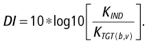
The DI is intended to help the technologist determine whether the image has been underexposed or overexposed. Just as with the other exposure indices, the DI is not an end all, be all indicator. Technologists must evaluate the image and, if in doubt about the image’s quality, consult with a radiologist. The radiologist has a higher-quality display than what is normally used for technologist workstations; an image that looks fine at the technologist’s workstation might show a great deal of noise and unwanted image interference at the radiologist’s workstation.
The DI can be used to adjust technical factors if the image must be repeated. A perfect image according to the DI has a DI value of 0.0. If the DI is negative, the image has been underexposed. If the DI is positive, the image has been overexposed. To raise the DI +1, increase technique by 20%. To decrease DI −1, decrease technique by 25%. This ±1 changes the KIND by +25% or −20%. This can also be expressed by saying that +1 is approximately 125% of the intended exposure; −1 is 80% of the intended exposure.
Do not rely on the DI as the sole determining factor of image quality. There are several variances that could cause the reading of the pixel values (Q) to be off, including the following:
• A prostheses within the image
• Gonadal shielding within the image
Any of these factors will cause the DI to fluctuate, and the technologist should consult with the radiologist regarding these image variances. The technologist should continue to use image noise as the true determining factor of image acceptance, and these standard values should be used only as a guide.
Image Quality Characteristics
Brightness
The brightness of a digital image refers to its appearance on the display monitor of the computer. The amount of light transmitted by the monitor as well as light reflected off the monitor can affect image appearance. According to the AAPM (Medical Physics Monograph No. 30), a monochromatic monitor uses a single electron beam and will have some overlap from line to line, and be susceptible to drift. In addition, if a monitor is monochromatic, reflection of the light in the room can be a problem. The phosphors produce white light that, when a clear glass monitor is used, the phosphor light escapes the monitor at a high rate. Ambient light is both reflected off the glass and penetrates the glass and reflects back, producing glare. To reduce glare, cathode ray tube (CRT) monitors are tinted so that the emitted light is decreased, and the faceplate glass is flat so that internal reflections are minimized. Controls are available to adjust the brightness of the computer monitor to minimize these issues.
When viewing images in any monitor, the technologist can adjust the brightness of the image using a technique called window level. Changing the window level makes the image brighter or darker. Manipulation of image brightness is discussed further in Chapter 3.
Contrast Resolution
Contrast resolution refers to the ability of the digital system to display subtle changes in the shade of gray. Higher-contrast resolution means that the differences between adjacent densities are enhanced; that is, more shades of gray may be demonstrated, resulting in the ability to differentiate between small differences in densities. Contrast resolution in digital imaging is directly related to the bit depth of the pixels in the image. With digital imaging, higher kilovoltage peak (kVp) values and lower milliampere-seconds (mAs) values can be used, lowering patient dose without affecting contrast nearly as much as was seen in film/screen radiography.
What contrast resolution in digital imaging does depend on is the amount of scatter. Digital systems are much more sensitive in recording scatter; therefore control of scatter is critical. Use of tight collimation and the correct grid will allow higher kVp values to be used without compromising contrast resolution. However, if contrast is too low it can be difficult, if not impossible, to separate the image signal from noise and background. Sufficient kVp for appropriate penetration of the tissues is still required so that enough gray tones exist to provide that signal separation. Screen resolution can be controlled by a technique called window width, in which the displayed tones are varied toward a longer or shorter scale. This is discussed further in Chapter 3.
Spatial Resolution
The ability of the imaging system to demonstrate small details of an object is known as spatial resolution. Just as the crystal size and thickness of the phosphor layer determines resolution in film/screen radiography, phosphor layer thickness and pixel size determines resolution in photostimulable phosphor (PSP) systems. The thinner the phosphor layer is, the higher the resolution. In film/screen radiography, resolution at its best is limited to approximately 10 line pairs per millimeter (lp/mm). In digital receptors, resolution is approximately 2.55 lp/mm up to 10 lp/mm in PSP systems, resulting in less detail. However, because of the dynamic range, or the ability to respond to varying levels of exposure, more tissue densities on the digital image are seen, giving the appearance of more detail. For example, an anteroposterior (AP) knee film/screen radiograph typically does not show soft tissue structures on the lateral aspects of the distal femur or proximal tibia or fibula. An AP knee digital image shows not only the soft tissue but also the edge of the skin (Figure 2-3). This is because of the wider dynamic recording range and does not mean there is additional detail. Spatial resolution comes down to this: the smaller the pixels, the higher the spatial resolution.
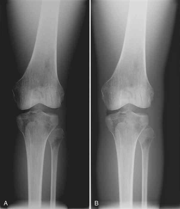
Modulation Transfer Function
To quantify gain or loss of resolution, a mathematical theorem was developed that stated that spatial resolution can be broken down into individual components and that the quality of each component affects the total amount of resolution. The ability of a system to record available spatial frequencies is known as modulation transfer function (MTF). The sum of the components in a recording system cannot be greater than the system as a whole. What that means is that when any component’s function is compromised because of some type of interference, the overall quality of the system is affected. MTF is a way to quantify the contribution of each system component to the overall efficiency of the entire system. MTF is a ratio of the image to the object; thus a perfect system would have an MTF of 1 or 100%. In digital detectors where x-ray photon energy excites a phosphor/scintillation layer and that phosphor produces light, there will always be a spreading out of the light that will reduce system efficiency; therefore the more light spread there is, the less the image looks like the object and the lower the MTF will be (Figure 2-4).
The black line shows high spatial frequency, which results in an MTF of 100%. The gray line shows a substantially lower spatial frequency, indicating system inefficiency. The closer the amplitude of the spatial frequency is to becoming a flat line, the lower the MTF.
Noise
Both in film/screen and digital imaging, anything that interferes with the formation of the image is considered noise. If superimposition of body parts occurs, that is known as anatomic noise. Noise that occurs during the acquisition of the image is known as radiographic noise and comprises equipment noise and quantum noise.
Equipment noise comes from noise in the detector elements and non-uniform detector responses. This cannot be controlled by the radiographer and is highly dependent on manufacturer, technology, and detector quality.
To place a relative value on noise, the noise power spectrum (NPS) is used. The NPS describes the spatial frequency content of the noise as well as spatial characteristics. The higher the NPS, the higher the noise is for a specific detector. Measuring NPS requires uniform exposures at specified beam qualities and exposures, followed by sophisticated mathematical measurements, the discussion of which is beyond the scope of this book.
When determining the appropriate exposure techniques to use for a particular body part, it must be decided by the radiologist and technologist how much noise can be tolerated in the image. This is known as signal-to-noise ratio (SNR). As the SNR increases, the noise decreases, but at a cost of higher exposure to the patient. Different detectors will require more or less exposure to the IR to achieve the same SNR. This can be difficult if there are multiple types of equipment from multiple vendors represented in one department. This is the reason for the push for a standardized exposure indicator mentioned earlier in the chapter.
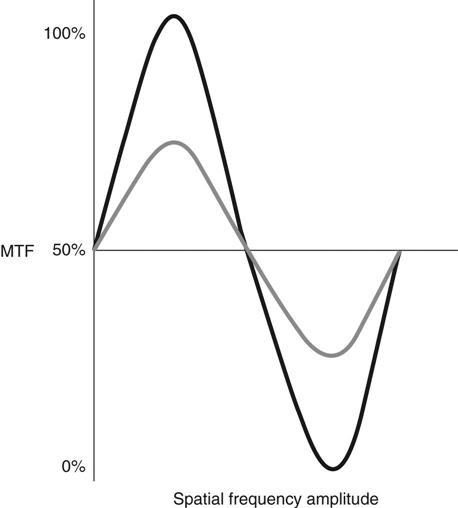
Exposure Latitude
Latitude refers to the range of exposure diagnostic image values the image detector is able to produce. It is those values that are just above background noise and higher and that refer to how much signal amplification is needed. Latitude is dependent on the image detector; the higher the dynamic range of the detector, the more values can be detected. In addition to the range of exposures and the way the detector responds within that range, images must have sufficient contrast resolution for the signal to be detected. The signal from the anatomic part must be appropriate and provide enough gray level so that its signal can be separated from background and noise. For example, when a homogenous object is x-rayed, there will be no contrast resolution, but when a heterogeneous object is x-rayed, there will be a great difference in adjacent tissues (Figure 2-5).
Detective Quantum Efficiency
How efficiently a system converts the x-ray input signal into a useful output image is known as detective quantum efficiency (DQE). DQE is a measurement of the percentage of x-rays that is absorbed when they hit the detector. The linear, wide-latitude input/output characteristic of PSP systems relative to screen/film systems leads to a wider DQE latitude for PSP systems, which implies that a PSP has the ability to convert incoming x-rays into “useful” output over a much wider range of exposures than can be accommodated with screen/film systems. Systems with higher quantum efficiency can produce higher-quality images at lower doses.
Amorphous selenium, amorphous silicon thin-film transistor (TFT), charge-coupled device (CCD), and complementary metal oxide semiconductor detector technology have increased DQE over PSP. Amorphous selenium detectors have the highest DQE, because they do not have the light conversion step and consequently no light spread. There is no light to blur the recorded signal output, a lower dose is required than for the others, and higher-quality images are produced. Newer complementary metal oxide semiconductor (CMOS) capture systems may be equal to direct image acquisition because of the crystal light tubes, which also prevent light spread.
The DQE of detectors changes with kVp, but generally the DQE of selenium systems is higher than that for PSP, CCD, and CMOS systems. CCD in particular has problems with low light capture.
The area of a TFT array is limited because of the structure of the matrix. This also affects the size and number of pixels available. Known as the fill factor, the larger the area of the TFT photodiodes, the more radiation can be detected and the greater amount of signal generated. Consequently, the greater the area of the TFT array, the higher the DQE.
Summary