CHAPTER 7 Diagnostic Shoulder Arthroscopy and Bursoscopy
PREOPERATIVE CONSIDERATIONS
Snyder1 has emphasized the importance of performing a complete 15-point glenohumeral examination and an 8-point bursoscopy examination in every arthroscopic shoulder procedure. Doing so will improve a surgeon’s arthroscopic skills in not only maneuvering the arthroscope, but also in diagnosing and treating almost all disorders of the shoulder joint arthroscopically.
ARTHROSCOPIC TECHNIQUE
In recent years, many advances have been made in shoulder arthroscopy, and we are now capable of performing complex arthroscopic shoulder procedures that were once deemed impossible. However, attention to detail is paramount, and this begins with the setup of the patient and the operating room. Every arthroscopic shoulder procedure requires careful preoperative and operative planning. The shoulder arthroscopist should always have a full complement of instruments available at all times, including cannulas, anchors, and suturing devices. The possibility of an arthrotomy should be discussed in advance with the patient in the event that pathology requiring an open approach is encountered. At the time of diagnostic arthroscopy, unexpected pathology can be found that may need to be addressed; it should not be ignored simply because the surgeon and staff did not have the proper instrumentation available or an adequate consent form signed.
Patient Positioning and Setup
Diagnostic shoulder arthroscopy and bursoscopy can be performed with the patient in the beach chair or lateral decubitus position. We prefer the lateral decubitus position using a commercially available arm supporter. The device is attached to the opposite side of the operating table via the Clark rail of the table. It is then rotated toward the operative shoulder. The arm is draped using a U-drape around the neck running distally and a 10-10 drape across the chest anterior to posterior. This draping is important because it prevents fluid extravasation onto the chest wall or neck. The entire extremity is prepped from the fingertips to the neck and axilla. A sterile shoulder sleeve is then affixed to the arm. The arm is supported by attaching the triangle at the end of the sleeve to the overhead cable ring using the sterile S hook (Fig. 7-1A). Ten pounds of weight using balanced suspension is attached to the upper cable for the average-sized person, but a few pounds more or less may be needed for larger or smaller limbs.1 The suspension device is color-coded so that the surgeon can advise the circulating nurse where to place the weight in an effort to abduct the shoulder for entrance into the glenohumeral joint or adduct the shoulder to facilitate entry into the subacromial space.
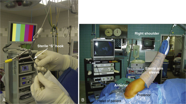
For diagnostic glenohumeral shoulder arthroscopy in the lateral decubitus position, the arm is positioned in 70 degrees of abduction and 15 to 20 degrees of forward flexion (see Fig. 7-1B). The surgeon stands behind the patient and the assistant is usually at the head of the table. If there is a second assistant or scrub tech, he or she stands behind the two surgeons. The drapes are allowed to drop over the head of the patient and the anesthesiologist can be at the head of the patient. The tubes and monitoring devices are stretched far enough so that the surgeon can walk around the head of the patient to the front to work anteriorly. All equipment is in front of the surgeon, including the video monitor, shaver, pump, and suction, with all tubes running off a Mayo stand on the other side of the patient. This prevents tangling of the multiple cords and tubing used in shoulder arthroscopy and also allows the surgeon easy and quick visibility of all equipment to ensure that everything is working properly during the procedure.
Use of a Trained Assistant
In private practice, or even in an academic setting, it is important to build your surgical team. Most shoulder arthroscopy is performed as an outpatient procedure and many are done in an outpatient surgery center. A surgical scrub technician can be trained to be a valuable first assistant for shoulder arthroscopy. By working together every week, operating room personnel learn your routine and the many steps involved in complex arthroscopic shoulder cases. Instructing them to hold the arthroscope properly allows the surgeon to use two hands to perform anchor placement, knot tying, and other parts of the arthroscopic procedure.
Surface Anatomy
With the arm supported in suspension, outlining the surface anatomy with a sterile marking pen is the next step before making any skin incisions. The supraclavicular fossa is first outlined; it is bordered anteriorly by the clavicle and acromioclavicular (AC) joint, laterally by the acromion, and posteriorly by the spine of the scapula. Next, the most outer or inferior edges of the clavicle, acromion, and spine of the scapula are palpated and dots are used as reference points (Fig. 7-2A). Connect the dots to define the most lateral acromial border, the S-shaped anterior edge of the clavicle, and the scapular spine posteriorly (see Fig. 7-2B). By palpating the most lateral aspect of the supraclavicular fossa, the AC joint is located at a 45-degree angle anteriorly (see Fig. 7-2C).
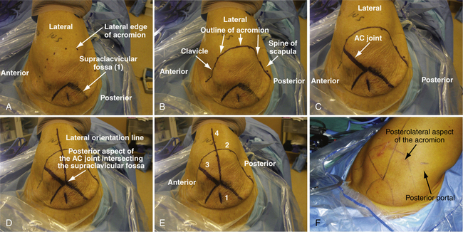
The lateral orientation line is drawn next. At the posterior aspect of the AC joint (i.e., the anterior edge of the supraclavicular fossa, where it intersects the AC joint), a line is drawn out laterally that crosses perpendicular to the lateral border of the acromion and extends distally 4 cm down the arm. This reference line divides the acromion into an anterior two fifths and posterior three fifths (see Fig. 7-2D and E). The orientation line is helpful as a reference when creating the lateral subacromial portal for decompression and arthroscopic rotator cuff repair procedures.1
Posterior and Anterizor Portal Creation
The first step in performing an arthroscopic evaluation of the glenohumeral joint is to create the posterior superior portal and to introduce the posterior cannula. In an average-sized individual, the entry point is approximately 2 cm inferior and 1cm medial from the posterolateral acromial edge (see Fig. 7-2F). For patients with thicker tissue or larger bony structures, the point is further inferior and medial.1 A 1-cm or smaller incision is made through the skin only with a no. 11 blade. The arthroscopic metal cannula with a blunt-tipped obturator is inserted through the posterior skin incision through the muscle until the posterior humeral head is palpated. With the opposite hand palpating the anterior surface of the shoulder joint, the humeral head is gently rotated back and forth. The opposite hand, which is placed anteriorly over the coracoid, should feel the movement of the humeral head. This also allows one to localize the joint line. The cannula is then directed medially and slightly inferior (raising your hand slightly) to slide medially off the humeral head. Aiming toward the coracoid process can be helpful in orientation when establishing this portal. Working the cannula through the capsule, one usually feels a definite popping sensation as the joint is entered. The arthroscope should then be placed into the cannula after the obturator is removed to verify placement and avoid multiple holes in the posterior capsule with repetitive attempts, which could lead to increased fluid extravasation.
A common error in making the posterior superior portal is to make it too lateral or proximal. The joint line is located inferior and medial to the posterolateral acromial corner.1 If difficulties are encountered in entering the glenohumeral joint, especially in larger patients, it is helpful to place 5 more pounds of suspension (total, 15 pounds). This provides more distraction and it is easier to palpate the step-off between the humeral head and glenoid with the tip of the blunt obturator. Never use excessive pressure or a sharp trocar in the cannula because penetration of the humeral head or scraping and damaging the articular surface can occur. After the capsule is punctured, the arthroscope is inserted to ensure that the cannula is truly in the joint and not in the subacromial space.1 If an extra 5 pounds of suspension had been added, removal at this time helps avoid inadvertent neurovascular compromise.
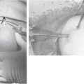
When the arthroscope is inserted into the posterior cannula, the joint is distended with an arthroscopic pump. The pump pressure is set between 30 to 60 mm Hg to maintain optimal visualization. The minimum pressure is maintained and adjusted frequently to control bleeding. The biceps tendon is visualized and the anterior portal can be created using an inside-out or outside-in technique. If an outside-in technique is used, a spinal needle is first placed to localize the portal (Fig. 7-3A) and the portal is created.
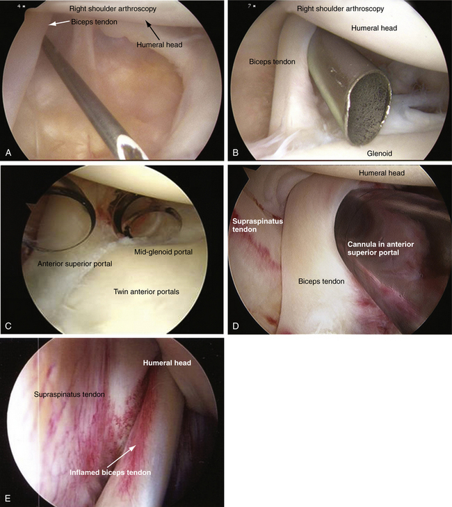
We prefer using an inside-out technique because it is quick, easy, and reproducible. The arthroscope is gently driven across the glenoid, just below the biceps tendon, and into the rotator interval. The arthroscope is removed and a blunt, smooth switching stick is inserted through the cannula, tenting the skin anteriorly. This requires little force and, if significant resistance is met, the switching stick may have migrated too superiorly into the supraspinatus tendon. A small stab incision is made at the tip of the rod and the rod is passed through the skin incision. A metal or plastic cannula is then inserted over the guide rod and gently twisted in until the capsule is penetrated. Using a metal cannula makes it easier to penetrate the anterior capsule and also is interchangeable so that the arthroscope can be easily switched from posterior to anterior during the diagnostic arthroscopy (see Fig. 7-3B).
The anterior portal is created in an anterior -superior position in the rotator interval between the anterior edge of the supraspinatus and the subscapularis tendons. By creating the portal superiorly, superior labrum anterior posterior (SLAP) pathology can be addressed as the angle for inserting a superior glenoid anchor is facilitated. This location also ensures a suitable viewing portal for evaluating anterior labral anatomy and pathology. It also ensures that there is adequate space for a second anterior midglenoid working portal, which can be created at the leading edge of the subscapularis tendon (see Fig. 7-3C).
Diagnostic Arthroscopy of the Glenohumeral Joint
With the patient in the beach chair or lateral decubitus position, a complete glenohumeral examination can be performed. The importance of a systematic 15-point glenohumeral diagnostic arthroscopy1 cannot be overemphasized and we recommend that it be performed during every shoulder arthroscopy. Proper arthroscopic handling, with rotation of the bevel of the arthroscope, allows systematic joint visualization. By rotating the arthroscope and using the angle of the arthroscopic lens to the surgeon’s advantage, it is possible to obtain a greater visual field without actually changing the position of the arthroscope within the joint. Nowhere is this more important than in the shoulder, where looking around the corner is a necessary skill. For this discussion, all the following arthroscopic manipulation positions described pertain to a right shoulder.
Position 1
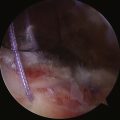
The first structure to be viewed in a systematic 15-point glenohumeral examination is the biceps tendon, followed by the superior labrum.1 For a right shoulder, the arthroscope is positioned with the 30-degree angle looking up at 11 o’clock. This allows the biceps to be visualized (see Fig. 7-3D) and, using the anterior cannula as a probe, the biceps can be pulled into the joint for inspection. Inflammation (see Fig. 7-3E) or partial tears of the biceps tendon can be hidden in the extra-articular portion or within the intertrabecular groove and may not be not readily visualized.
Rare variants of the biceps tendon, including a partial or conjoined tendon, complete intra-capsular position, or absence of the tendon, may be encountered.2 A double structure (bifid) of the long head of the biceps tendon has been reported.3 The vincula biceps can occasionally be seen; these are small strands of mesentery-like synovium that pass from the biceps tendon to the surrounding synovium and capsule. On occasion, if robust enough, the vinculae can prevent retraction of a torn proximal biceps.1
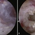
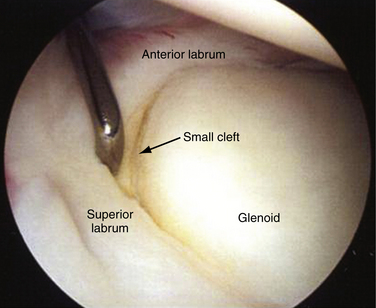
The 30-degree bevel of the arthroscope is then rotated down to about the 8 o’clock position and the superior labrum is visualized. Again, using the edge of the cannula as a probe, the superior labrum can be palpated at its attachment to the superior glenoid. Stoller4 has described three different types of attachment for the biceps labral complex (BLC) to the glenoid. A type 1 BLC is firmly attached to the superior glenoid, with no sublateral foramen in the anterosuperior quadrant. A probe can be inserted through the anterior superior portal to palpate the labrum (Fig. 7-4). A type 2 BLC is attached several millimeters medial to the sagittal plane of the glenoid, and articular cartilage continues to coat the superior aspect of the glenoid surface underneath the labrum. A small cleft between the glenoid and labrum is not uncommon. In a type 3 BLC, the labrum is meniscoid in shape, loosely attached, and exhibits a large sulcus that projects under the labrum and over the cartilaginous pole of the glenoid. This should not be confused with a type II SLAP tear. Traction on a normal biceps tendon should not produce arching or detachment of the labrum away from the superior glenoid.1
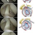
A degenerative superior labrum (type I SLAP) is also normal and can be débrided, but does not treatment (Fig. 7-5A). A type II SLAP tear demonstrates granulation tissue between the glenoid and superior labrum, and is best visualized when a probe retracts the damaged labrum (see Fig. 7-5B). A type III SLAP lesion is a split of the superior labrum (see Fig. 7-5C) whereas a type IV SLAP lesion represents a split that extends into the biceps and may be fragmented (see Fig. 7-5D).
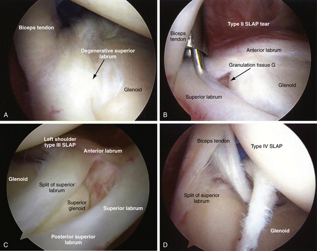
FIGURE 7-5 A, Degenerative superior labrum (type I SLAP lesion) is a normal finding and requires no treatment. B, Type II SLAP tear has granulation tissue between the glenoid and the superior labrum. C, Type III SLAP lesion has a split within the superior labrum. D, Type IV SLAP lesion is shown, extending into the biceps.
Position 2
For a right shoulder, the arthroscopic bevel is rotated counterclockwise to approximately 6 o’clock and the arthroscope is retracted slightly to visualize the posterior labrum. If the arthroscope is gently lifted, visualization of the posterior labrum, along with the posterior capsular recess, is improved (Fig. 7-6A). The posterior capsular recess appears as a deep fold of tissue posterior to the labrum.1 The arthroscope is rotated in a counterclockwise fashion to the 5 o’clock position to visualize the entire posterior labrum to the posterior inferior edge.
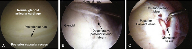
A degenerative posterior labrum is common in older patients and can be débrided but does not require a repair (see Fig. 7-6B). A posterior Bankart lesion may demonstrate granulation tissue in addition to a detached labrum (see Fig. 7-6C).
Position 3
The arthroscope is rotated again in a counterclockwise fashion to the 4 o’clock position to visualize the posterior inferior axillary recess. Rotating the bevel to the 3 o’clock position visualizes the posterior capsular attachment to the humeral head. Capsular tears originating from the humeral attachment can be detected.
Position 4
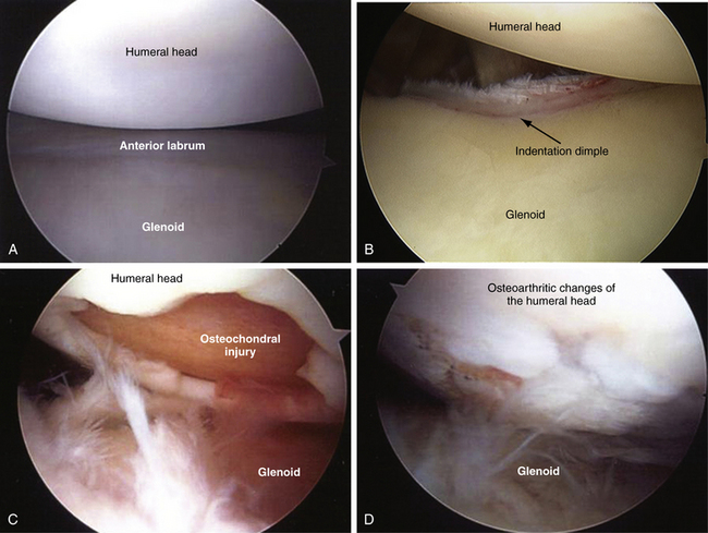
The arthroscope is rotated back in a clockwise fashion from the 3 to the 6 o’clock position and the glenoid articular surface and humeral head are seen (Fig. 7-7A). The center of the glenoid usually has a very thin appearance, a common finding in almost all shoulders. Along the anterior edge of the glenoid, there is an indentation dimple, which demarcates the superior two fifths from the inferior three fifths of the glenoid. This represents the point of fusion of the two ossific centers of the glenoid; it can be very deep and resemble an old fracture (see Fig. 7-7B).1 Osteochondral injuries other than Hill-Sachs lesions can be seen involving the humeral head (see Fig. 7-7C) or osteoarthritic changes involving the humeral head (see Fig. 7-7D).
Position 5
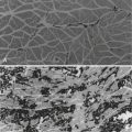
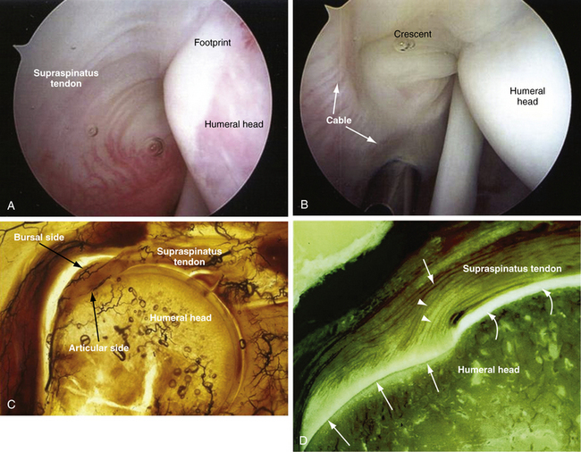
The arthroscope is rotated in a clockwise fashion to the 10, 11, 12, and 1 o’clock positions to visualize the undersurface of the supraspinatus tendon. By rotating in this systematic manner, one can visualize the attachment of the supraspinatus tendon to the greater tuberosity, the so-called footprint (Fig. 7-8A). In a normal shoulder, this portion of the rotator cuff has a firm attachment to the anatomic footprint of the bone. The rotator cuff ridge or cable is a thickening of the capsular tissue. It is an extension of the coracohumeral ligament extending perpendicular from the main body of the ligament as it courses from the coracoid to the humerus. Above the lateral border of the rotator cuff ridge is a concave portion known as the crescent (see Fig. 7-8B).1,5 The rotator cuff ridge resembles the cable of a suspension bridge. The outer border of the cable surrounding the crescent extends anteriorly to the biceps and posteriorly to the inferior border of the infraspinatus, thereby spanning the supraspinatus and infraspinatus insertions. The rotator cable was found to a substantial structure, averaging 2.59 times the thickness of the rotator cuff that it surrounded.5 It is thought that the tears that maintain the cable or are cable-dominant can maintain function and strength, because the crescent is stress-shielded by the cable. A crescent-dominant shoulder is not stress-shielded by the cable. The area of the crescent has a poor vascular supply, as seen on histologic slides, compared with the bursal side of the cuff and demonstrates poor healing potential (see Fig. 7-8C).6 The collagen fibers of the articular side of the rotator cuff are also thinner and less uniform as compared with the bursal-sided fibers, which are thicker and run more parallel (see Fig. 7-8D).
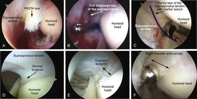
From this position, one can detect partial articular-sided supraspinatus tendon (so-called PASTA) avulsions medial to the attachment of the humeral head (Fig. 7-9A). Full-thickness tears can also be seen from this position (see Fig. 7-9B). An absorbable marker suture (PDS; polydioxanone) can be placed via a spinal needle to mark the location of the partial cuff tear (see Fig. 7-9C) and this can be later visualized in the subacromial space. Quantifying the degree of an articular-sided partial rotator cuff, the most common type of partial tear, is important in decision making. Studies indicate a supraspinatus footprint averaging 12 to 14 mm (range, 9 to 22 mm; see Fig. 7-9D).7 The amount of exposed footprint from the edge of the articular surface to the tendon can help estimate the amount of footprint exposed (see Fig. 7-9E). Using a tool with a known width can help measure the exposed portion of the footprint and can help estimate the amount of tendon that is torn (see Fig. 7-9F).
Position 6
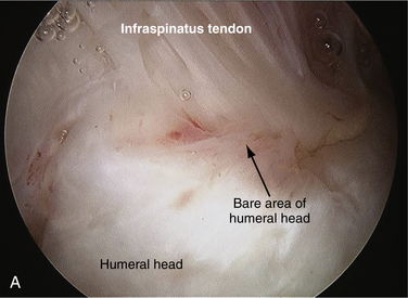
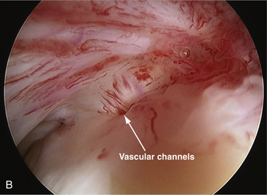
After examining the supraspinatus tendon and its attachment to the humeral head, the arthroscope is withdrawn slightly and the bevel is rotated slightly to about the 1:30 o’clock position, following the cuff attachment to the bare area of the humeral head. If the scope is withdrawn too far, it will slip out of the glenohumeral joint. The normal bare area can vary in size from a few millimeters to 2 to 3 cm in diameter. The bare area is the gap between the articular surface and inferior insertion of the infraspinatus tendon insertion (Fig. 7-10A).7 There is no articular cartilage in this region and there are frequently indentations and sometimes deep holes representing vascular access channels to bone (Fig. 7-10B). This should not be confused with a Hill-Sachs lesion, which is usually found more medially.1
Position 7
The arthroscope is rotated medially slightly from the bare area and the bevel is rotated counterclockwise and then clockwise to visualize the articular cartilage of the humeral head. The arm can be internally and externally rotated to visualize the entire humeral head.1
Position 8
After visualizing the articular cartilage of the humeral head, the arthroscope is rotated more medially with the bevel at the 1 o’clock position to visualize the anterior superior triangle of the shoulder joint. The anterior superior triangle area includes the anterior superior labrum, superior glenohumeral ligament, the superior edge of the subscapularis tendon, and middle glenohumeral ligament (Fig. 7-11A). A discrete superior glenohumeral ligament is seen approximately 40% of the time.8 It extends from the superior labrum at the glenoid tubercle to the upper portion of the lesser tuberosity, crossing the subscapularis superiorly and often having a common insertion with it at the lesser tuberosity (see Fig. 7-11B).1 This common insertion of the subscapularis and superior glenohumeral ligament is shared with the coracohumeral ligament and forms the reflection pulley, which is a ligamentous sling that stabilizes the long head of the biceps as it enters into the intertubercular groove.9 The anterior capsular ligaments can also be covered with a sheetlike veil, where they are partially (see Fig. 7-11C) or completely obscured or incorporated into the capsule (see Fig. 7-11D), or can also be totally absent.
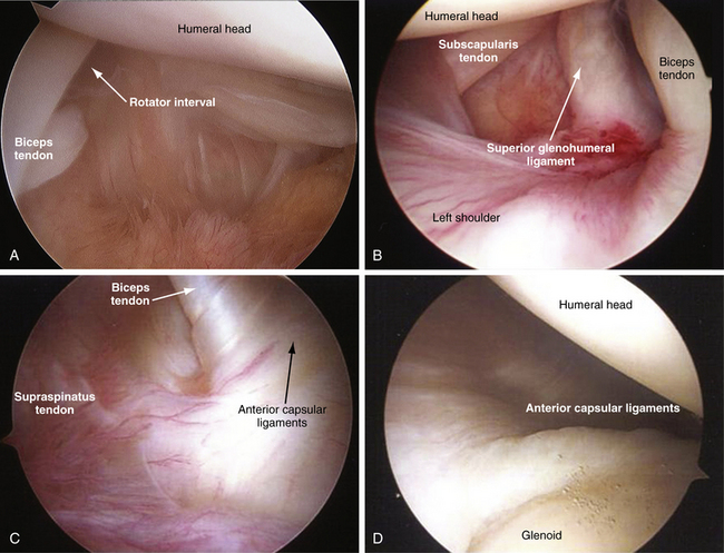
FIGURE 7-11 A, Anterosuperior triangle area bordered by anterosuperior labrum, superior glenohumeral ligament, and rotator interval. B, Discrete superior glenohumeral ligament is seen in 40% of patients. The anterior capsular ligaments are covered with a sheetlike veil, where they are partially (C) or completely (D) obscured, or even incorporated into the capsule.
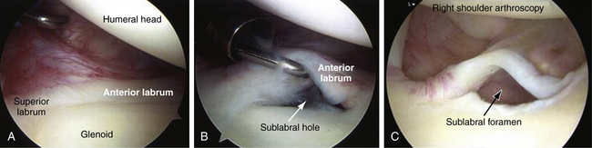
With typical anatomy, the anterior superior labrum firmly attaches to the glenoid rim (Fig. 7-12A).1 The presence of a normal anterior sublabral hole or foramen is present from 14% to 18.5% of the time.1,8 The size of this sublabral foramen can vary from a few millimeters, visible only when the labrum is retracted with a probe (see Fig. 7-12B), to a distinct foramen seen without any probing see (Fig. 7-12C). This anterosublabral foramen can involve the entire anterosuperior quadrant must be differentiated from a SLAP or Bankart lesion.10
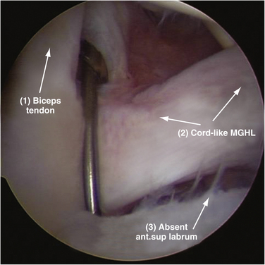
A variation of a normal sublabral foramen, the Buford complex, may be seen in 6% to 6.5% of shoulders.1,8,11 A Buford complex has a cordlike middle glenohumeral ligament that attaches to the superior labrum just anterior to the base of the biceps anchor and crosses the subscapularis tendon at a 45-degree angle. It is also associated with an absent anterosuperior labrum (Fig. 7-13).
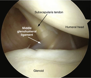
The arthroscope is rotated to the 2 o’clock position to visualize the subscapularis tendon and middle glenohumeral ligament. The subscapularis tendon passes vertically from its humeral head attachment at the lesser tuberosity to disappear below the glenoid rim. The middle glenohumeral ligament crosses the subscapularis tendon at a 45-degree angle to insert on the anterosuperior neck of the glenoid or just medial to the labrum (Fig. 7-14).1 It is present in more than 90% of shoulders, usually appearing as a thin sheet (70%). However, it can be a thicker structure and sometimes cordlike (21%), bifid (1%), absent (7%), or even just a thickening of the capsule.10
Position 9
The arthroscope is rotated clockwise to the 3 o’clock position to visualize the anteroinferior labrum and its attachment to the glenoid. In approximately 95% of cases, the labrum has a smooth attachment to the neck of the glenoid and fuses with the edge of the articular cartilage (Fig. 7-15). In approximately 5% of cases, there is a meniscoid type of labral attachment in which the articular edge of the labrum is separated from the glenoid. A probe can be inserted between the articular surface of the glenoid and overlying labrum but the capsular attachment to the labrum is fully intact and does not separate from the glenoid when traction is applied.1
Position 10
The anterior capsular ligaments insert into the labrum and are firmly attached to the neck of the glenoid. There is often a thickening of the capsule superiorly, representing the superior band of the inferior glenohumeral ligament. This is the primary restraint to anterior translation of the humeral head in the abducted, externally rotated position. Other than this fold of tissue, the capsular tissues are smooth and covered with a thin synovial lining.1
Position 11
With the arthroscope in the anterior superior portal and the bevel at the 12 o’clock position, the posterior and posterior superior capsules are visualized. In rare cases, a posterior capsular detachment called a reverse humeral avulsion of the glenohumeral ligament (RHAGL) lesion is encountered.1 The bevel is then rotated clockwise to the 4 o’clock position to visualize the posterior labrum. In most cases, the posterior labrum is firmly attached to the glenoid rim but, like the superior and anterior labrum, can also be meniscoid in nature.
Position 13
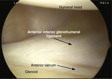
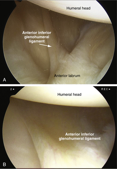
The arthroscope is then again slightly withdrawn and the tip is flipped back around the biceps tendon again to the superior glenoid. The bevel is rotated counterclockwise to the 9 o’clock position and the anterior labrum is visualized along the anteroinferior glenohumeral ligament. The superior band of the inferior glenohumeral ligament is well developed in approximately 80% of cases and poorly developed in 20%.8 When well developed, it can be a thick, cordlike structure (Fig. 7-16A) or a wide band of tissue (see Fig. 7-16B) that attaches to the anterior labrum near or slightly above the midglenoid notch. When poorly developed or underdeveloped, it can be associated with congenital laxity. It is important that the shoulder arthroscopist be comfortable viewing from this position because acute or chronic anterior labral tears (Bankart lesions) can occasionally only be visualized from this position.
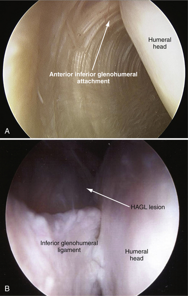
By rotating the arthroscope from the 9 o’clock position upward to the 11 o’clock position, the superior band of the inferior glenohumeral ligament can be followed up to its attachment on the humeral head. It is helpful to have your assistant lift the arm because this allows better visualization of its humeral attachment (Fig. 7-17A). This is an important step because a humeral avulsion of the glenohumeral ligament (HAGL) lesion, an uncommon source of recurrent shoulder instability, can be overlooked (see Fig. 7-17B).1
Position 14
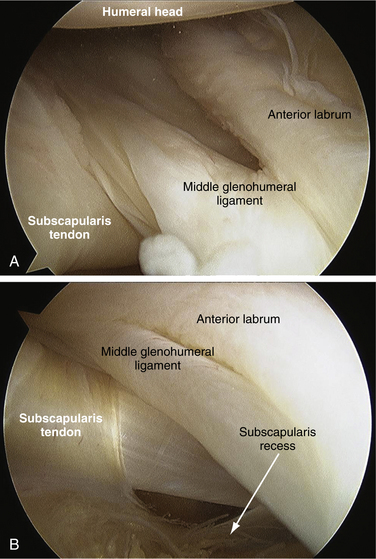
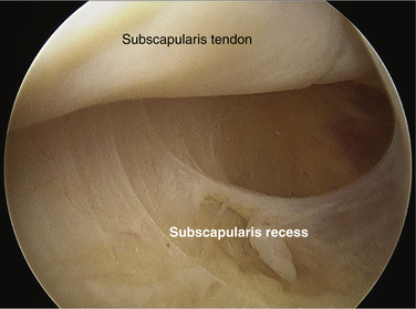
The arthroscope is retracted slightly and the middle glenohumeral ligament is found by rotating from the 11 o’clock position counterclockwise to approximately the 7 o’clock position. The anterior attachment of the middle glenohumeral ligament inserts into the labrum of the glenoid neck after it crosses the subscapularis tendon (Fig. 7-18A). By withdrawing the arthroscope slightly, one can visualize the opening of the subscapularis recess (see Fig. 7-18B). The leading edge of the subscapularis tendon is followed medially into the subscapularis recess. The arthroscope is then rotated counterclockwise to 6 o’clock and then 5 or 4 o’clock to evaluate the entire subscapularis recess, a common place for loose bodies (Fig. 7-19).1
Diagnostic Bursoscopy of the Subacromial Space
Diagnostic bursoscopy is an important part of the thorough arthroscopic shoulder evaluation and should be done in every shoulder, even if the pathology is thought to be within the glenohumeral joint. If not, significant bursitis or partial rotator cuff tears may be missed and patients may continue to have pain or other symptoms, which could have been easily addressed had the subacromial space been examined.
Position 1
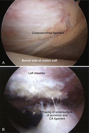
The arthroscope is positioned with the acromion above and the rotator cuff below, and the bevel at the 1 o’clock position. The coracoacromial (CA) ligament and the synovium covering the ligament are seen. In a normal subacromial space, the CA ligament is smooth, with no evidence of fraying and no reactive inflammation of the bursa (bursitis) noted (Fig. 7-20A). There can be a mild amount of bursitis or inflammation in the subacromial space in a normal shoulder. Inspection of the anterior margin of the acromion may reveal the crabmeat-like fraying of tissue that is the hallmark of mechanical impingement (see Fig. 7-20B). There can also be severe inflammation and bursitis with severe fraying of the CA ligament.
Position 2
The arthroscope is rotated clockwise to the 2 and then 3 o’clock positions to follow the roof of the bursa to the lateral edge of the acromion. There is often a thin, lateral subacromial shelf of bursal tissue extending from anterior to posterior. This may sometimes be very thick and can adhere to the top of the rotator cuff. It should not be confused with the underlying rotator cuff tissue.1
Position 4
The arthroscopic bevel is rotated clockwise to about the 6 o’clock position to visualize just medial to the tendon bone junction. The assistant slowly internally and externally rotates the humerus so that the entire bursal side of the rotator cuff footprint or attachment can be visualized.1 This is the area where most early cuff tears are first located and where a marker can usually be found if it had been placed via a spinal needle into a partial articular-sided supraspinatus tendon avulsion (PASTA) tear (Fig. 7-21A). It is often necessary to gently débride the bursa with a shaver to visualize the bursal side of the rotator cuff adequately.

This is also where more advanced tears and most bursal calcifications are situated. These calcific deposits can be soft (see Fig. 7-21B) or hard, and associated with inflammation. The intrinsic blood supply to the tendon is poor in this location.1,6
Position 5
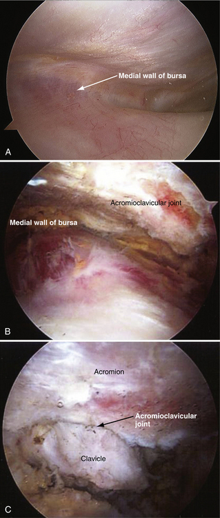
To view the medial wall of the bursal cavity, the arthroscopic bevel is rotated in a clockwise fashion to the 8:30 or 9 o’clock position. This bursal wall separates the subacromial space from the subclavicular region. This should be smooth, and is often filled with fatty tissue (Fig. 7-22A). The spine of the scapula can be viewed by removing some of the fatty tissue and bursal tissue covering it.1 The AC joint can also be seen if some of the fatty tissue and the bursal tissue are removed (see Fig. 7-22B). A degenerative AC joint has loss of articular cartilage at the distal end of the clavicle (see Fig. 7-22C).
Position 6
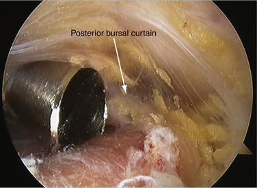
The posterior bursal curtain is viewed looking straight posteriorly from the anterior portal. It is located on a line extending from the posterior margin of the acromioclavicular joint to the lateral border of the acromion (Fig. 7-23).1 This is the structure that can obstruct the view of the arthroscope when it is in the posterior portal and the tip of the arthroscope is behind it. This structure can be very thick and scarred in chronic rotator cuff disease or impingement.
Position 7
The arthroscope is then rotated laterally in a counterclockwise direction to the 9 o’clock position to view the posterior attachment of the rotator cuff. The assistant rotates the arm internally and externally to check the entire attachment of the supraspinatus and infraspinatus tendons. Posterior cuff calcifications can also be seen with this maneuver.1
Position 8
The arthroscope is then withdrawn slightly, rotating the bevel to the 7 o’clock position to view the anterior aspect of the rotator cuff and the area of the biceps groove. Pivoting the arthroscope by raising the camera head allows one to see down the front of the shoulder into the rotator interval space and the subscapularis tendon.1
SUMMARY
The more diagnostic shoulder arthroscopy and bursoscopy are performed, the more the surgeon is comfortable recognizing normal anatomy and anatomic variants. The use of videography and archiving video clips and pictures allow the surgeon to review unusual and difficult cases with colleagues, and helps expand the surgeon’s knowledge and understanding of this complex joint.
PEARLS&PITFALLS
1. Snyder SJ Diagnostic arthroscopy of the shoulder: normal anatomy and variations. Snyder SJ, editor. Shoulder Arthroscopy, 2nd ed. Philadelphia: Lippincott, Williams & Wilkins; 2003:22-38.
2. DePalme AF. Surgery of the Shoulder. Philadelphia: JB Lippincott; 1983.
3. Yanmis I, Ogoz E, Weisler E, et al. Double long head of the biceps brachii tendon. Tech Shoulder Elbow Surg. 2005;6:125-127.
4. Stoller DW. MRI, Arthroscopy and Surgical Anatomy of the Joints. Philadelphia: Lippincott-Raven; 1999.
5. Burkhart S, Esch J, Jolson S The rotator cuff crescent and rotator cuff cable: an anatomic description of the shoulder’s “suspension bridge”. Arthroscopy, 9; 1993:611-616.
6. Rathbun JB, Macnab I. The microvascular pattern of the rotator cuff. J Bone Joint Surg Br. 1970;52:540-553.
7. Curtis A, Burbank K, Tierney J, et al The insertional footprint of the rotator cuff: an anatomic study. Arthroscopy, 22; 2006:603-609.
8. Ilahi A, Labbe M, Cosculluela P. Variants of the anterosuperior glenoid labrum and associated pathology. Arthroscopy. 2002;18:882-886.
9. Weishaupt D, Zanetti M, Tanner A, et al Lesions of the reflection pulley of the long biceps tendon: MR arthrographic findings. Invest Radiol, 34; 1999:463-469.
10. Snyder S, Karzel RP, Del Pizzo W, et al. SLAP lesions of the shoulder. Arthroscopy. 1990;6:274-279.
11. Williams MM, Snyder SJ, Buford D The Buford complex—the “cord-like” middle glenohumeral ligament and absent anterosuperior labrum complex: A normal anatomic capsular variant. Arthroscopy, 10; 1984:241-247.