CHAPTER 6 Diagnostic Imaging of the Elbow
INTRODUCTION
Imaging technology has expanded dramatically over the past decade (Box 6-1). However, evaluation of the elbow still relies heavily on routine radiographs or computed radiography (CR) images. Optimal hard copy radiographs, or CR images, are essential to properly select additional studies and are required for accurate interpretation of other modalities such as magnetic resonance (MR) imaging.7
Conventional tomography is rarely performed today. However, computed tomography (CT) has increased in utility with new multidetector systems that provide rapid evaluation of numerous bone and soft tissue disorders.3 Arthrography also can be an important tool in the diagnosis of intra-articular disorders of the elbow. Today, conventional, CT, and MR arthrography play important roles for evaluating the articular cartilage, intra-articular anatomy, and supporting structures of the elbow.7
Magnetic resonance imaging (MRI) frequently is used to evaluate subtle osseous and soft tissue abnormalities. Soft tissue contrast is superior to that achieved with CT. MRI scans can be obtained in any plane, which is an additional advantage. Intravenous or intra-articular injection of gadolinium provides additional information in selected cases.23
RADIOGRAPHY/COMPUTED RADIOGRAPHY IMAGING
An understanding of the process by which routine radiographs or CR images are obtained is essential. Factors such as the type of equipment, patient positioning, and radiation dose must be kept in mind when determining the necessary views in a given clinical setting. In obtaining views of the elbow, we routinely use a 48-inch target film distance with 50 to 60 kVp, 600 ma, and an exposure time of 0.0125 seconds. Reusable CR or regular cassettes measuring 10 × 12 inches are routinely employed.1,4,5
A minimum of two projections is necessary for evaluation of the elbow. Anteroposterior (AP) and lateral views of the elbow are taken at 90-degree angles and fulfill these criteria. In trauma patients, we routinely obtain oblique views as well.1,5
ANTEROPOSTERIOR VIEW
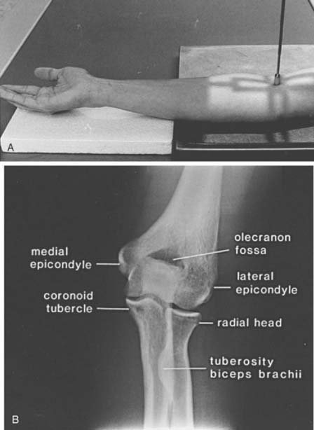
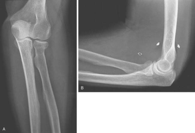
The AP view (beam enters the patient anteriorly and the film is posterior) is obtained by placing the patient adjacent to the radiographic table in a sitting position (the supine position may be used if the patient is injured). The patient should be positioned with the extended elbow at the same level as the cassette so that the extremity is in contact with the full length of the cassette.1,4 The hand is supinated, and the beam is centered perpendicular to the elbow (Fig. 6-1A). The AP view demonstrates the medial and lateral epicondyles and the radiocapitellar articular surface (Fig. 6-1B). Assessment of the trochlear articular surface and at least a portion of the olecranon fossa is also possible. The normal carrying angle (5 to 20 degrees, average 15 degrees) can be measured on the AP view.1,5
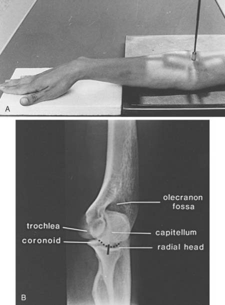
LATERAL VIEW
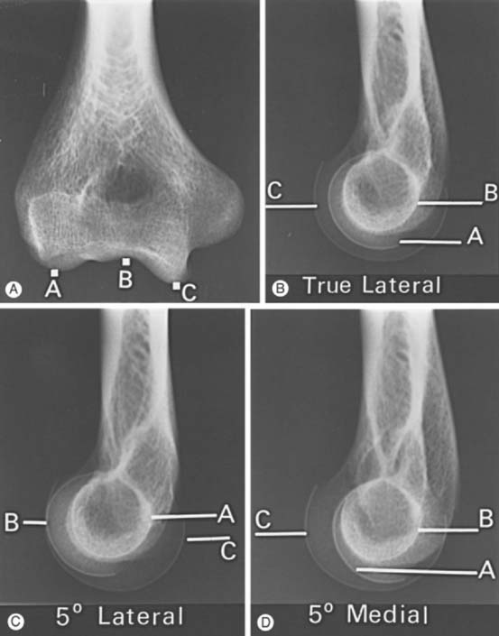
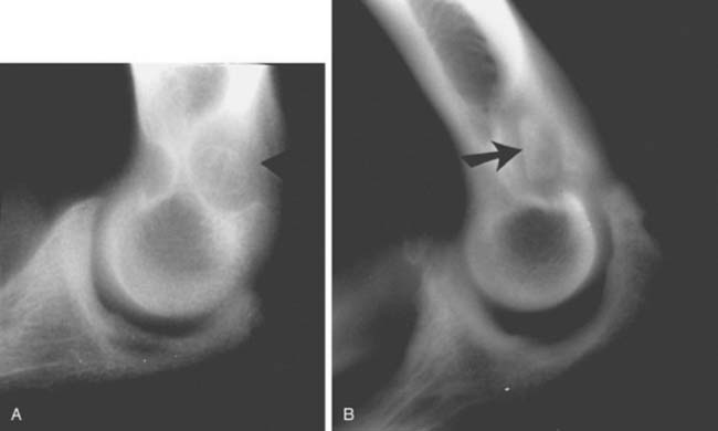
The lateral view is obtained by flexing the elbow 90 degrees and placing it directly on the cassette. The hand is positioned with the thumb up so that the forearm is in the neutral position; the beam is perpendicular to the humerus (Fig. 6-2A). This view provides good detail of the distal humerus, elbow joint, and proximal forearm. The coronoid of the ulna, which cannot be readily seen on the AP view, and the olecranon are well visualized on the lateral view (see Fig. 6-2B). Because the articular surface makes a valgus angle of about 7 degrees to the long axis of the humerus (see Chapter 2), a lateral view of the arm does not provide a lateral view of the joint. If the x-ray beam is parallel to the articular surface, three concentric arcs can be identified (Fig. 6-3A-D).5 The smaller arc is the trochlear sulcus, the intermediate arc represents the capitellum, and the largest arc is the medial aspect of the trochlea. If the arcs are interrupted, a true lateral view has not been obtained. Unfortunately, in patients with acute injury, true AP and lateral views are often difficult to obtain. Patients are frequently unable to extend or flex the elbow fully. In these situations, the tube must be angled and the cassette positioned to simulate these views as closely as possible.1,4,5
OBLIQUE VIEWS
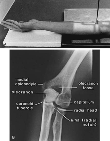
Oblique views are obtained by initially positioning the arm as if one were taking the AP view. For the medial oblique projection (Fig. 6-4A and B), the arm is positioned with the forearm and arm internally rotated approximately 45 degrees (see Fig. 6-4A). This view allows improved visualization of the trochlea, olecranon, and coronoid (see Fig. 6-4B). The radial head is obscured by the proximal ulna. The lateral oblique view is taken with the forearm, hand, and arm rotated externally (Fig. 6-5A). This projection provides excellent visualization of the radiocapitellar joint, medial epicondyle, radioulnar joint, and coronoid tubercle (see Fig. 6-5B).1,4,5
RADIAL HEAD VIEW
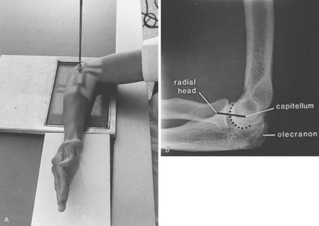
Radial head fractures are a common clinical problem and are often difficult to visualize on radiographs or CR images. The radial head view may define the fracture more clearly.16,17,28 This view (Fig. 6-6A and B) is easily accomplished by positioning the patient as one would for the routine lateral view. The tube is angled 45 degrees toward the shoulder joint (see Fig. 6-6A). The radial head view projects the radial head away from the ulna, allowing subtle changes to be more easily identified (see Fig. 6-6B), and it also may allow better visualization of the fat pads.1,16,17
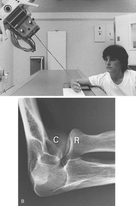
FIGURE 6-6 Radial head view. A, The patient is positioned as if a routine lateral view (see Fig. 6-2A) were to be obtained. The tube is angled 45 degrees toward the humeral head rather than perpendicular to the joint. B, Radial head view projects the radial head (R) clear of the olecranon and clearly demonstrates the capitellum (C) and radiocapitellar joint.
AXIAL VIEWS
Occasionally, suspected pathology of the olecranon or epicondyles prompts further evaluation with axial views. Figure 6-7A and B demonstrate the axial projection used to evaluate the epicondyles, olecranon fossa, and ulnar sulcus. The patient’s elbow is flexed approximately 110 degrees, with the forearm on the cassette and the beam directed perpendicular to the cassette. This view is also helpful in detecting subtle calcification in patients with tendonitis. The olecranon process may be better observed on the reverse axial projection (Fig. 6-8A and B).1,4,5
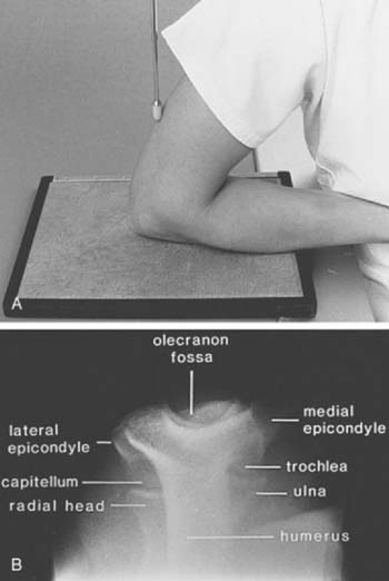
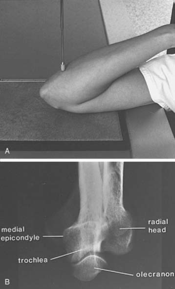
FIGURE 6-8 A, The patient’s arm is placed on the cassette, with the elbow completely flexed. The central beam (pointer) is perpendicular to the cassette. B, The radiograph demonstrates the olecranon, trochlea, and medial epicondyle. Contrast this view with that of Figure 6-7B.
Other views of the elbow also may be used,1,4,5 but those just discussed are usually sufficient. In fact, when questions arise regarding routine AP, lateral, and oblique views, a CT scan with reformatting in the coronal and sagittal planes or an MRI scan is frequently obtained instead of special views.
ASSESSMENT OF RADIOGRAPHS/COMPUTED RADIOGRAPHY IMAGES
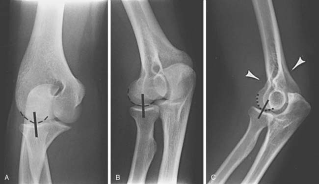
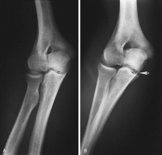
The relationship of the radial head to the capitellum should be constant regardless of the view obtained (Fig. 6-9A-C).5,26,28 The radius is normally bowed at the level of the tubercle. Therefore, the line should be drawn in the midpoint of the radial head, not extended to include this portion of the radial shaft.
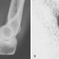
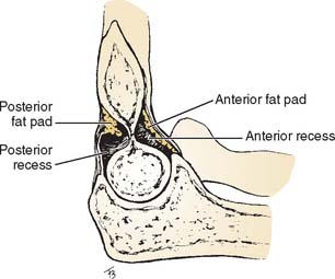
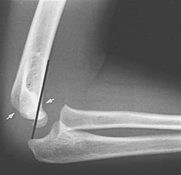
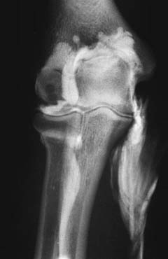
Careful evaluation of the fat pads and supinator fat stripe is essential. These structures are best observed on the lateral (see Fig. 6-2) and radial head (see Fig. 6-6) views. The anterior and posterior fat pads are intracapsular but extrasynovial.5,8,10,26,28 The anterior fat pad is normally visible on the lateral view. The posterior fat pad is obscured owing to its position in the olecranon fossa (Fig. 6-10). Displacement of the fat pads, particularly the posterior fat pad, is indicative of an intra-articular fluid collection due to inflammation or hemarthrosis due to trauma.5,8,10,26,28 Norell26 reportedthat 90% of children with displaced posterior fat pads had elbow fractures. This finding is less specific in adults, but if present in patients following trauma (see Fig. 6-9C), a fracture is likely. Cross-table lateral views may be more specific. A lipohemarthrosis, which is more specific for an intra-articular fracture, may be evident.5,26,28
The supinator fat stripe lies anterior to the radial head and neck on the surface of the supinator muscle. Fractures of the elbow frequently displace or obliterate this structure, providing a clue to the underlying injury (Fig. 6-11). Rogers and MacEwan28 reported changes in the fat stripe in 100% of fractures of the radial head and neck and in 82% of other elbow fractures.
The anterior humeral line helps detect subtle supracondylar fractures in children but is not used as frequently for adults. This line, drawn along the anterior humeral cortex, should pass through the middle third of the capitellum (Fig. 6-12).5
STRESS VIEWS
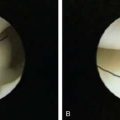
In patients with suspected ligament disruption or instability, varus and valgus stress views are desirable and may be diagnostic. Ideally, these examinations should be performed with fluoroscopic guidance. This allows proper positioning of the elbows. Also, visualization of subtle changes in the articular distance may be evident while stress is being applied. Fluoroscopic images should be obtained in the neutral position and during valgus and varus stress. Accuracy may be hindered by guarding and swelling following acute injury. In this situation, anesthetic injection should be performed before the examination. In the normal elbow, the joint should not open when stress is applied. We have arbitrarily chosen an increase in the joint space of greater than 2 mm as being abnormal (Fig. 6-13A and B). The relationship of the tip of the olecranon in the fossa is also helpful in interpreting radiographic instability. The normal elbow carrying angle also may increase significantly if ligament instability is present.5
COMPUTED TOMOGRAPHY
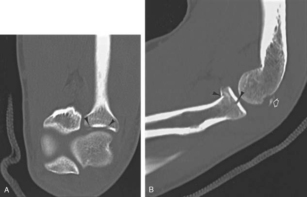
Conventional tomography is rarely performed today due to the improved utility of CT and new fast multi detector CT systems. CT is useful in the evaluation of bone and soft tissue abnormalities.5,19 Articular deformities, complex fractures with multiple fragments and other conditions can be evaluated quickly and reformatted into coronal and sagittal planes. Three-dimensional reconstructions can also be obtained. Thin sections using 0.5- to 1.0-mm slices can be easily reconstructed (Fig. 6-14A and B).19 We frequently use CT in combination with arthrography to more clearly define articular or capsular abnormalities.5,30
ARTHROGRAPHY
Elbow arthrography provides valuable information about capsule size, the synovial lining, supporting ligaments, and the articular surfaces of the joints. Needle access also permits fluid aspiration for laboratory studies and diagnostic or therapeutic injections.6 The most common indications for this procedure are the detection of possible loose bodies, evaluation of articular cartilage, and the demonstration of capsular/ligament injuries. Loose bodies may be osteocartilaginous, owing to osteochon dromatosis or osteochondral fragments due to acute trauma, or osteochondritis dissecans. Less commonly, arthrograms are performed to evaluate capsule size in patients with adhesive capsulitis.5,7,12,14,20,32
TECHNIQUE
To obtain maximum information, arthrography should be performed by an experienced physician with a thorough understanding of the patient’s clinical situation. Review of the routine radiographs or CR images is essential. These images often provide clues that dictate subtle changes that indicate which imaging technique (conventional, CT, MRI) should be employed following the injection of the contrast material. The choice of contrast material and indications for conventional, CT, or MR arthrography are highly dependent on the clinical setting (Table 6-1).7,31
| Indication | Technique |
|---|---|
CT, computed tomography; MR, magnetic resonance.
Contrast agents include air, iodinated contrast material, or a combination of the two for conventional or CT arthrography and gadolinium diluted in iodinated contrast and anesthetic for MR arthrography. Radiographs or CR images are obtained immediately following injection of contrast medium to avoid dilution thatreduces image quality. CT and MR arthrography should be performed within 30 and 45 minutes following injection, respectively. If longer delays are expected, this dilutional phenomenon can be prevented by combining 0.3 mL of 1:1000 epinephrine with the contrast agent.5,7,31,32
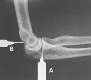
The procedure can be performed with the patient positioned either sitting adjacent to the radiographic table or lying prone on the table (Fig. 6-15). Determination of the best position depends on the equipment available and the patient’s condition. In either position, the elbow is flexed 90 degrees, with the lateral aspect toward the examiner. Before the injection of contrast agent, fluoroscopic evaluation of range of motion and evidence of possible ligament stability or loose bodies should be accomplished.5
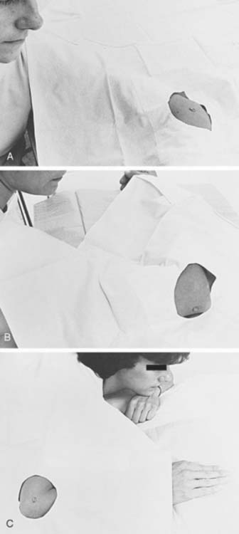
The elbow is then prepared using sterile technique. One of two injection sites may be used. In most cases, a lateral approach into the radiocapitellar joint is selected. In patients with previous radial head resection or suspected lateral ligament injury, a posterior approach is more suitable. With the posterior approach, the elbow is again flexed 90 degrees, and the medial and lateral epicondyles and olecranon are palpated. The needle is placed an equal distance between these points and is positioned fluoroscopically (Fig. 6-16). If the needle is properly positioned, the contrast medium will flow away from the needle tip as it is injected. If the needle is not properly positioned, the contrast agent collects at the needle tip and significant resistance is encountered.
Following the injection, the needle is removed and the elbow is studied fluoroscopically. This step is essential in evaluating stability of the joint and loose bodies. Routine films or CR images include AP, lateral, and both oblique views. Medial and lateral cross-table lateral views provide additional information with double contrast technique.5,32 CT images are obtained using thin sections (1 mm) with reformatting in the coronal and sagittal planes. MRI scans are also obtained in the axial, coronal, and sagittal planes with fat-suppressed T1-weighted images and at least one T2-weighted series as periarticular cysts may not communicate with the joint.7,31
NORMAL FINDINGS
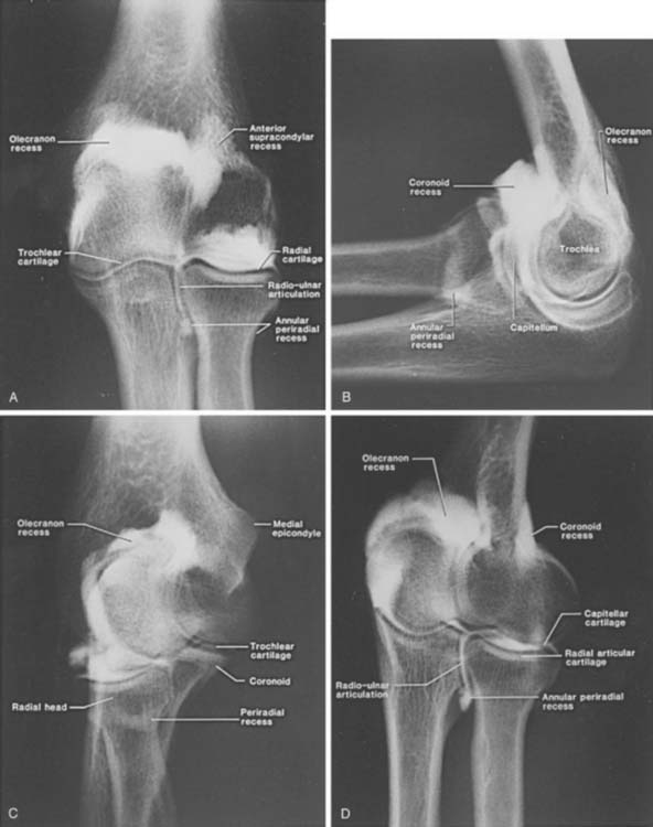
In the normal conventional arthrogram (Fig. 6-17A-D), the radiocapitellar, ulnotrochlear, and radioulnar joints can be identified. The anterior (coronoid), posterior (olecranon), and annular recesses also are visualized.
The normal joint capacity is 10 to 12 mL. This may increase to 18 to 22 mL in patients with chronic instability, or it may be decreased in patients with capsulitis or flexion contracture.5
ABNORMAL FINDINGS
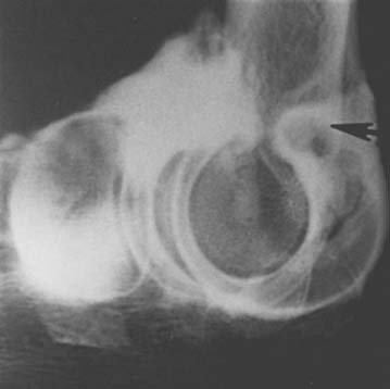
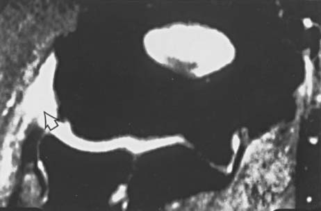
“Loose bodies” may be either attached to the synovium or actually free within the joint. If they are free, they can be observed fluoroscopically or demonstrated on images by contrast that completely surrounds the structure (Fig. 6-18).5,7,31Differentiation of a loose body in the olecranon fossa from the normal os supratrochlear dorsale is possible because of the nature of the trabecular pattern and the cortical thickness. Most symptomatic densities in the olecranon fossa have prominent trabeculae and sclerotic cortical margins (Fig. 6-19B). The normal ossicle has sparse trabeculae and a thin cortical rim (see Fig. 6-19A).5,27
MR arthrography is preferred to exclude ligament/capsular tears, although conventional techniques may demonstrate the tear when they are complete (Figs. 6-20 and 6-21). Extravasation of contrast material on conventional images indicates a tear (see Fig. 6-20). Care must be taken not to mistake extravasation at the needle site for a rent of the capsule. Therefore, the needle should not be placed near the area of suspected injury regardless of the imaging technique selected. If a lateral tear is suspected, a posterior approach should be used.5
COMPLICATIONS
Complications due to elbow arthrography are rare. Freiberger13 reports an incidence of infection of approximately 1 in 25,000 cases. Effusions may occur whether contrast material or air is used; they usually occur within 12 hours and may result in pain and joint stiffness.5,13,31 The joint fluid may have a turbid appearance owing to the high eosinophil count.5
The patient should be questioned about possible allergy to the contrast medium (iodinated or gadolinium). Although it is rare (0.1% of patients affected),13 this complication must be kept in mind. Urticaria is the most common reaction experienced, and often no treatment is necessary. In more severe cases, antihistamines may be required. Most allergic reactions occur in the first 30 minutes after the injection. Premedication with an antihistamine may be used in patients with suspected allergy. These patients should be observed for 1 or 2 hours following the procedure.
MAGNETIC RESONANCE IMAGING
MRI of the elbow can clearly define numerous types of osseous and soft tissue pathology. Improved soft tissue contrast and numerous image planes provide advantages over CT and other imaging techniques.7,31 Intra-articular contrast injection using gadolinium, as described previously, affords advantages provided with conventional arthrography and additional information regarding subtle synovial and cartilage abnormalities. Intravenous gadolinium is useful for detection of early synovial inflammation and enhancement of other lesions such as osteomyelitis and neoplasms.2,5,7
Surface coils generally are used to improve image quality. For patient comfort, the arm should be placed at the side when possible. When the arm is raised above the head, there is often motion artifact resulting in image degradation.5,7
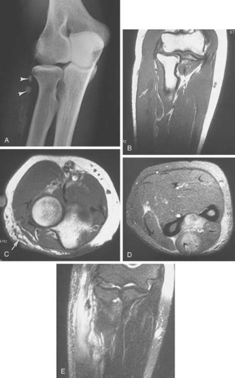
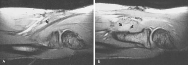
MR pulse sequences are designed to demonstrate contrast differences between normal and abnormal tissues. Multiple pulse sequences and image planes are required to identify and stage pathology. Often, the axial plane is combined with sagittal (Fig. 6-22) or coronal images for initial screening.5,7 In certain situations, new fast-scan techniques are used to allow motion (pronation-supination or flexion-extension) studies to be performed. Pronation-supination maneuvers (Fig. 6-23) are most easily performed, because MR gantry size limits ranges of flexion and extension. Newer open magnets provide more flexibility for motion.7
ULTRASONOGRAPHY
Ultrasound applications for musculoskeletal imaging have expanded dramatically from the late 1970s. Improved technology and image quality permit more accurate depiction of normal anatomy and pathologic lesions. Ultrasonography is also more readily available and less expensive than MRI.5,21,24,25
Ultrasound uses mechanical vibrations whose frequencies are beyond audible human perception (about 20,000 Hz or cycles per second). Imaging of most musculoskeletal structures is accomplished in the 7- to 12-MHz range.21,24 Doppler ultrasonography for peripheral vascular studies is performed in the 8-MHz range.25 New Doppler scanners provide color flow data that allow different flow rates (venous, arterial) to be easily demonstrated.5,25
The central component of ultrasound instruments is the transducer, which contains a piezoelectric crystal. The transducer serves as a transmitter and receiver of sound waves. By applying the vibrating transducer to the skin surface (through an acoustic coupling medium such as mineral oil or gel), the mechanical energy is transmitted into the underlying tissues as a brief pulse of high-energy sound waves. Sound waves reach different tissue interfaces (acoustic impedances), resulting in reflection or refraction. The reflected sound waves return to the transducer, where they are converted into electrical energy used to produce the image.5,21,24,25
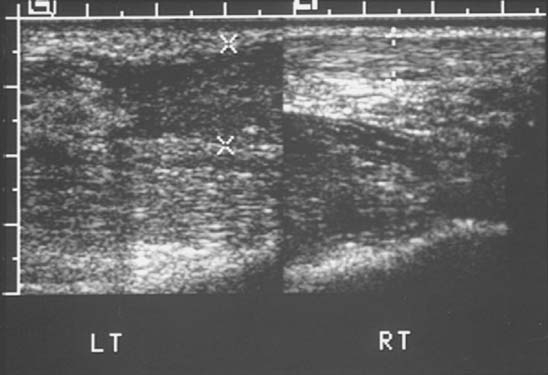
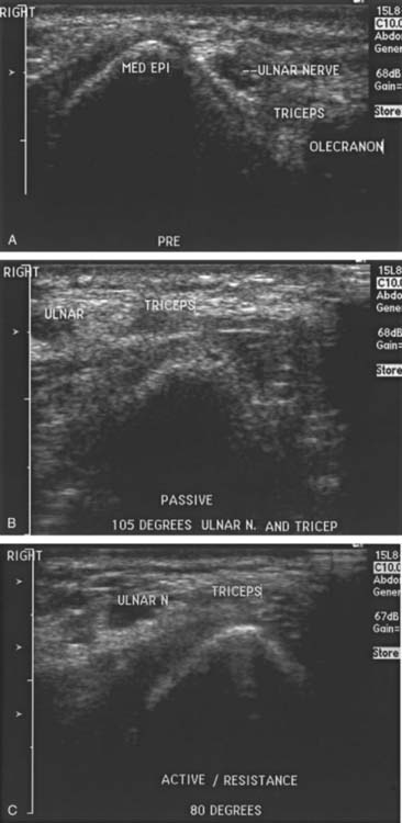
Ultrasound, once limited to evaluating solid and cystic soft tissue lesions, is now commonly employed to evaluate articular and periarticular abnormalities. In the elbow, ultrasonography is well suited for evaluating tendon (Fig. 6-24) and nerve (Fig. 6-25) pathology. Tendon tears are demonstrated as gaps or areas of abnormal echo texture compared with the normal tendon (see Fig. 6-24). Avulsed bone fragments or calcifications are hyperechoic with posterior acoustic shadowing.21 Cost and flexibility of this technique will, no doubt, result in increased orthopedic use.24
RADIONUCLIDE SCANS/POSITRON EMISSION TOMOGRAPHY
There are numerous isotopes and indications for radionuclide imaging of the musculoskeletal system.5 Bone scans are typically obtained after intravenous injection of 10 to 20 mCi (370-740 MBq) of technetium-99m–labeled methylene diphosphonate. Images are obtained 2 to 4 hours after injection. Common indications include primary or metastatic bone lesions, subtle fractures, non-accidental trauma in children and other causes of suspected osseous related pain.5
Three-phase bone scans use the same isotope and dose, but images are obtained in the initial 60 seconds after injection, followed by blood pool images at 2 to 5 minutes and delayed images at 3 to 4 hours. Indications for three phase scans include differentiation of cellulitis from osteomyelitis, bone infarction, reflex sympathetic dystrophy, and peripheral vascular disease.5,29
Bone marrow scintigraphy is performed using 10 to 15 mCi (370-555MBq) of technetium-labeled sulfur colloid. Images are obtained approximately 15 minutes after injection. Lead shields are placed over the abdomen to delete counts from the liver and spleen. Bone marrow imaging is most often performed to evaluate marrow replacement disorders and patients with joint prostheses.5
Special approaches may be required in patients with suspected infection. A normal bone scan or three-phase bone scan virtually excludes the possibility of infection. These techniques are sensitive but not specific. Therefore, when there is a high index of suspicion, more specific approaches are generally employed. White blood cells labeled with indium-111 or technetium or technetium-labeled antigranulocyte antibodies provide more specificity.15,22
Indium-111-labeled leukocyte scans are performed 18 to 24 hours after intravenous injection of the isotope. Technetium-labeled leukocytes or antigranulocyte antibody imaging is performed 2 to 4 hours after injection. Technetium is more readily available, and image resolution is superior to Indium-111 studies. Gallium-67 citrate scans can also be used to identify infection. Scanning is performed 24 to 72 hours after injection. This isotope is less commonly used today.9 Combined studies (i.e., technetium and white blood cells or indium-111 and technetium sulfur colloid) may be required in chronic infections or in the presence of orthopedic implants or prostheses.5,9,22
Positron emission tomography (PET) has provided a new physiologic approach to imaging musculoskeletal disorders, specifically infection and neoplasms.11,18 Positron-emitting agents include flourine-18-deoxyglucose, L-methyl-carbon 11, and oxygen 15. Flourine-18 has a half life of 110 minutes compared with the shorter half life of 20 and 21 minutes respectively for the other agents. Therefore, flourine-18 is the clinical agent of choice. Flourine-18-deoxyglucose imaging demonstrates increased glucose use seen with active disease processes. Patients must be fasting for 4 hours before the study. No sugared beverages should be taken, and blood sugar should be normal for optimal studies. Scanning is performed 1 hour after injection. Early studies demonstrate that PET imaging is more accurate than the studies described above for evaluating infection, chronic infection, and infection associated with orthopedic fixation devices or arthroplasty. PET is also more useful than conventional isotopes for detection of tumor activity and metastasis.11,18
1 Ballinger P.W., Frank E.D.. 10th ed.. Merrill’s Atlas of Radiographic Positions and Radiologic Procedures, Vol. 1. C.V. Mosby Co., St. Louis, 2003;89.
2 Beltran J., Chandnani V., McGhee R.A. Gadopentatate dimeglumine-enhanced MR imaging of the musculoskeletal system. A. J. R. 1991;156:457.
3 Berland L.L., Smith K.L. Multi-detector array CT. Once again new technology creates new opportunities. Radiology. 1998;209:327.
4 Bernau A., Berquist T.H. Positioning Techniques in Orthopedic Radiology. Orthopedic Positioning in Diagnostic Radiology. Baltimore: Urban and Schwartzenberg, 1983.
5 Berquist T.H. Imaging of Orthopedic Trauma, 2nd ed. New York: Lippincott-Raven Press, 1992.
6 Berquist T.H. Diagnostic/therapeutic injections as an aid to musculoskeletal diagnosis. Semin. Intervent. Radiol. 1993;10:326.
7 Berquist T.H. MRI of the Musculoskeletal System, 5th ed. Philadelphia: Lippincott-Williams and Wilkins, 2006.
8 Bohrer S.P. The fat pad sign following elbow trauma. Clin. Radiol. 1970;21:90.
9 Boutin R.D., Joachim B., Sartoris D.J., Reilly D., Resnick D. Update of imaging of orthopedic infections. Orthop. Clin. North Am. 1998;29:41.
10 Corbett R.H. Displaced fat pads in trauma to the elbow. Injury. 1978;9:297-298.
11 De Winter F., Van de Wiele C., Vogelaers D., de Smet K., Verdonk R., Dierckx R.A. Flourine-18 fluorodeoxyglucose-positron emission tomography. A highly accurate imaging modality for diagnosis of chronic musculoskeletal infections. J. Bone Joint Surg. 2001;83A:651.
12 Eto R.T., Anderson P.W., Harley J.D. Elbow arthrography with the application of tomography. Radiology. 1975;115:283.
13 Freiberger R.H., Kaye J.J. Arthrography. New York: Appleton Century Crofts, 1979.
14 Godefroy G., Pallardy G., Chevrot A., Zenny J.C. Arthrography of the elbow: anatomical and radiological considerations and technical considerations. Radiology. 1981;62:441.
15 Gold R.H., Hawkins R.A., Katz R.D. Bacterial osteomyelitis: findings on radiography, CT, MR and scintigraphy. A. J. R. 1991;157:365.
16 Greenspan A., Norman A. The radial head, capitellar view. Another example of its usefulness. A. J. R. 1982;139:193.
17 Greenspan A., Norman A. The radial head, capitellar view. Useful technique in elbow trauma. A. J. R. 1982;138:1186-1188.
18 Guhlmann A., Brecht-Krause D., Suger G., Glatting G., Kotzerke J., Kinzl L., Reske S.N. Flourine-FDG PET and technetium-99m labeled antigranulocyte antibody scintigraphy for chronic osteomyelitis. J. Nucl. Med. 1998;39:2145.
19 Haapamaki V.V., Kiuru J.J., Koskinen S.K. Multi-detector computed tomography diagnosis of adult fractures. Acta Radiol. 2004;45:65.
20 Hudson T.M. Elbow arthrography. Radiol. Clin. North Am. 1981;19:227.
21 Jacobson J.A., van Holsbeeck M.I. Musculoskeletal ultrasonography. Orthop. Clin. North Am. 1998;29:135.
22 Kaim A., Ledermann H.P., Bongartz G., Messmer P., Müller-Brand J., Steinbrich W. Chronic post-traumatic osteomyelitis of the lower extremity: comparison of magnetic resonance imaging and combined bone scintigraphy with radio labeled monoclonal antigranulocyte antibodies. Skel. Radiol. 2000;29:378.
23 Kramer J., Hofmann S., Die M.R. Magnetic resonance arthrography: benefits and indications. Adv. M. R. I. Contrast. 1997;4:104.
24 Lin J., Fessell D.P., Jacobson J.A., Weadock W.J., Hayes C.W. An illustrated tutorial of musculoskeletal ultrasound. A. J. R. 2000;175:637.
25 Merritt C.R.B. Doppler color flow imaging. J. Clin. Ultra. 1987;15:591.
26 Norell H.G. Roentgenologic visualization of the extracapsular fat. Its importance in the diagnosis of traumatic injuries to the elbow. Acta Radiol. 1954;42:205.
27 Obermann W.R., Loose H.W.C. The os supratrochlear dorsale: a normal variant that may cause symptoms. A. J. R. 1983;141:123.
28 Rogers S.L., MacEwan D.W. Changes due to trauma in the fat plane overlying the supinator muscle: a radiographic sign. Radiology. 1969;92:954.
29 Rupani H.D., Holder L.E., Espinola D.A., Engin S.I. Three phase radionuclide bone imaging in sports medicine. Radiology. 1985;156:187.
30 Singson R.D., Feldman F., Rosenberg Z.S. The elbow joint: assessment with double contrast CT arthrography. Radiology. 1986;160:167.
31 Steinbach L.S., Palmer W.E., Schweitzer M.E. MR arthrography. RadioGraphics. 2002;22:1223.
32 Weston W.J., Dalinka M.K. Arthrography. New York: Springer Verlag, 1980.