Chapter 11 Diagnostic equipment
 General diagnostic imaging systems allow practitioners to perform the fundamental clinical examinations within the radiography department.


INTRODUCTION
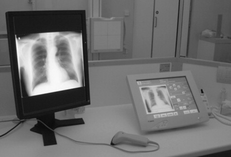
Within the imaging department there is a range of equipment and accessory items to assist the practitioner in obtaining optimal quality images. Technological developments have seen the introduction of digital capturing systems (digital radiography, DR) and advancements in operator ergonomics, patient throughput and comfort. Modern general X-ray rooms should be spacious, permitting the examination of a wide spectrum of patients (Fig. 11.1).
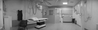
The use of relatively high proton number materials to provide radiation protection measures has generally remained unchanged in the last fifteen years. Walls of a general X-ray room may be coated with barium plaster, and lead shielding is incorporated into access routes. Consideration is also given to the ceilings and floors of any X-ray examination room if the radiology department is situated in proximity to adjoining floors within a hospital.
IMAGING TABLES
The majority of imaging tables utilised within general diagnostic departments have to meet a number of key requirements to ensure patient safety and the provision of optimal image quality. Modern imaging tables are designed to minimise unnecessary strain on practitioners during examinations and provide security and comfort for patients (Fig. 11.2). The availability of a variable height feature permits easy transfer of patients, whether they are walking, in a chair or on a stretcher. A wide range of movement is available, usually via foot control switches situated at the base of the table, and this prevents the need to move the patient around on a draw sheet and minimises injury to the practitioner. Controls positioned at either side of the imaging table also provide a universal approach to transferring and positioning patients.
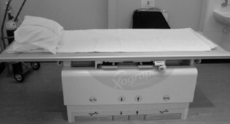
Most modern imaging tables are designed using low attenuation materials, such as carbon fibre, which have the advantages of being lightweight and strong to accommodate the weight of the heavy individuals, typically up to 450 kg.1 Using materials such as carbon fibre also absorbs less of the primary beam and reduces radiation dose when undertaking grid work. Carbon fibre is also warm to the touch and has rounded edges to prevent physical damage to patients and staff and the build up of electrostatic charge.
Modern imaging tables also accommodate direct capture imaging plates, which are linked to a monitor and computer unit for a near instantaneous display. The advent of digital imaging has redefined clinical practice in terms of patient positioning and appropriate use of a DR system. Traditional systems employ integrated conventional cassette units, which also act as a scatter minimisation unit. Such systems are also linked to automatic exposure devices (AED). The use of the AED has become a routine aspect of clinical work. There are normally three AED chambers integrated into the tabletop mechanism. Selection of the appropriate chamber(s) is facilitated by pre-set protocols with a manual override if the practitioner needs to change the programme to provide an optimum image, or if the patient has a metal prosthesis (e.g. hip), affecting the overall quality of the image. The density settings on the control console may be password protected to prevent changes to optimal stored values.2
The use of automatic cassette size sensing (ACSS) techniques ensures the collimation from the light beam diaphragm matches the size of the cassette within the Bucky mechanism. This reduces the area irradiated and produces less scattered radiation, improving image quality as well as limiting radiation dose to the patient and staff. Closer collimation can again be performed, as the diaphragms are not fixed in the position sensed by the ACSS.
TUBE SUPPORTS
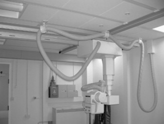
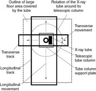
Modern general X-ray tubes are supported via a ceiling track mechanism which is able to withstand the rigour and demands of a typical department workload (Fig. 11.3). Most clinical departments utilise ceiling suspended units and employ a ‘cross track’ mechanism to allow the unit to move swiftly over a large floor space. The tube support facilitates movement around the longitudinal, transverse and vertical axes. The telescopic column provides a flexible range of vertical movement and is supported by electromechanical locks. The ceiling in imaging rooms containing a ceiling mounted unit needs to be of a reasonable height, thus permitting the required SID for a range of examinations.
Health and safety requirements for an X-ray tube
not as flexible as a ceiling mounted system. Such units are limited in their range of movement and the practitioner should take this into consideration when undertaking more complex examinations or with non-ambulant patients. Floor mounted systems are positioned on a track unit which is recessed into the floor and secured to a ceiling track for added stability. This design limits the available floor space and may present health and safety challenges.
The major advantages of a ceiling suspended unit include:
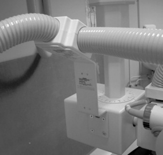
High-tension cables are securely encased in protective flexible piping, which is supported by additional ceiling sockets (Fig. 11.5). This enables the practitioner to safely manoeuvre the X-ray unit without the risk of placing unnecessary stress upon the high-tension cables. The supports for the cables must run freely along the track to prevent any mechanical strain when the X-ray tube is rotated.
CASSETTES AND FILM HOLDERS
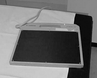
Typically, if a department is employing either conventional cassettes or CR technology, there will be a range of image receptor sizes to accommodate various radiographic techniques. All image receptor devices should be stored away from primary and scattered radiation, ideally in an appropriately designed storage holder. Routine quality control assessments of the image capturing devices should also be performed, in particular the routine secondary erasure of unused CR cassettes. Direct capture units (Fig. 11.6) may either be mobile devices or fixed units (e.g. chest imaging unit). Such units are expensive and require proper storage facilities when not employed.
To undertake a range of diagnostic techniques, the modern imaging environment should include various ancillary items. These include cassette holders, foam pads, stationary grid units, sandbags and radiation protection devices (e.g. lead rubber coats). The practitioner is required to utilise a range of skills and knowledge in order to produce optimal quality images. The use of a cassette holder to acquire images may minimise radiation dose to staff or carers.
Cassette holders may take the form of a basic device, such as the example shown in Figure 11.7, and are generally employed for techniques such as lateral horizontal beam hip examinations. However, a modern upright Bucky mechanism with an integrated cassette holder is also a crucial feature in a general imaging room.

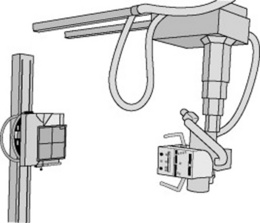
Figure 11.8 demonstrates the advantages of a ceiling mounted X-ray unit and upright Bucky unit. The provision of standard interlocks also ensures set geometry for chest examinations, which need to be at a standardised distance of approximately 180 cm SID. This aids in the minimisation of geometric unsharpness for certain examinations.
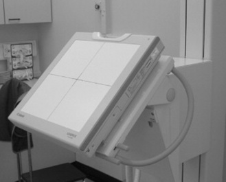
A variable height facility supported by either manual or electromechanical locks enables the assembly to be moved up and down to examine a range of procedures, from lateral cervical spines to erect standing knees. The cassette support mechanism may then be removed to facilitate AED or Bucky work. The system can also be rotated 90 ° into a horizontal position if required for adapted techniques, such as a lateral elbow in plaster or wrists on patients who may be immobile. Modern upright DR units (Fig. 11.9), which possess an integrated image capturing device, may also be used for a wide range of examinations and allow flexible rotation. All upright units should possess patient positioning aids, such as handles and chin rests. Also the provision of electromechanical interlocks will prevent any compromise of patient safety in the event of an electrical failure.
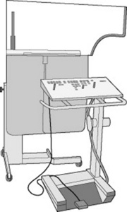
OPERATOR CONSOLE AND DOSE RECORDING FEATURES
General X-ray units are supported with space saving control consoles (Fig. 11.10), which encompass touch screen facilities. This is coupled with the small space required for a high frequency generator to supply power to the X-ray unit. The use of solid state electronics provides accurate exposure times for examinations and improves image quality at lower patient doses by producing a nearly constant potential voltage waveform which is not possible with a single or three phase power supply.3 The creation of a near constant potential waveform helps to reduce the possibility of movement unsharpness during radiographic procedures. This is especially true for paediatric examinations, where very short exposure times may be required.
Most operator consoles have preset anatomically programmed (APR) exposure values, which are stored on a microprocessor. The pre-set radiographic exposures provide prompt access to a digital bank of typical values used in clinical practice. However, practitioners still require the knowledge and skills to adjust these pre-set values in order to provide optimal image quality at the lowest possible dose.4
Typical power ratings for a high voltage generator for general radiography procedures are in the region of 30–55 kW. This is generally lower than for units such as interventional systems, which require greater power supplies due to the demands placed on them.5
Practitioners have a duty to ensure minimal exposure values are used in order to produce optimal diagnostic radiographs.6 The development of radiological equipment has assisted in the promotion of minimal exposures, optimal image production and the provision of a safe working environment. Rooms are designed to ensure the operator console is at a safe distance from the examination table and erect Bucky unit. Unlike in mobile equipment, the exposure button is attached to the console, thus preventing an exposure unless the practitioner is safely behind the protective lead glass screen.
It is a legal requirement to record radiation doses to patients, and whilst an integrated dose area product (DAP) meter does not reduce radiation dose, it does facilitate easy recording of the entrance dose to the patient being examined in that room. This allows the practitioner to measure the dose and ensure it is within the diagnostic reference level (DRL) required by the Ionising Radiation (Medical Exposure) Regulations 2000.6 The meter can easily demonstrate the effect of close collimation and this can encourage good working practices by the practitioner. DAP units display the dose given to the patient in milligrays (mGy) or centigrays (cGy) and this must be recorded for each study undertaken.
The provision of features such as exposure hold, which prevents an exposure-taking place for a number of reasons, minimises a potentially unsafe examination from taking place.7 Reasons may include the door to the radiology department being opened during the examination, the X-ray tube not being correctly centred to the Bucky tray, no cassette in the Bucky tray or a cassette in both the upright and table Bucky systems.
MOBILE EQUIPMENT
Mobile X-ray units are rechargeable (capacitor discharge) in design, being generally safer than mains units, which draw power for exposures from wall sockets. This reduces the necessity for the provision of dedicated electrical sockets on wards such as ITU and CCU, where interruptions to the local power supplies are generally not recommended. However, a mains powered unit is lighter in design and has a smaller footprint, which aids with manoeuvrability of the system.3
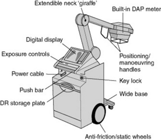
Features of a typical mobile X-ray unit are demonstrated in Figure 11.11. Mobile units may vary in design, with some units possessing extendible tube supports or adjustable-height mobile units. Extendable tube supports or adjustable-height mobile units should aim to provide a good range of movements, including a generous source–image distance (SID) and subtle adjustments for minor angle corrections.
Modern systems should be easy to use, flexible and provide high quality images. Typically, most modern mobile units are compact in design to enable movement in confined spaces, such as in isolation rooms. Most mobile X-ray units are designed to enable the provision of an optimal imaging service and are supplied with similar X-ray tubes to those in general X-ray rooms, with typical anode angles of 15 °, and provide 8500 revolutions per minute during an exposure.6 The mobile X-ray tube and its housing are customised for its role, needing to provide the same level or radiation protection as those in the department but at a minimal weight. Modern mobile units use a single focal spot size of 0.8 mm, giving a compromise between acceptable geometric unsharpness and tube life.
Additional features aiding manoeuvrability include a lightweight construction of the base unit and a design that enhances the operator’s visibility when travelling. This is a crucial issue during transportation, where mobile units may be in close proximity with members of the public within the hospital. A small electrical motor can be used to provide a motorised drive within the unit to help promote the ease of movement.5 Radiography is a profession that is particularly conscious of the potential manual handling risks that can be incurred while undertaking such a physical occupation on a day-to-day basis.2 Modern advances are aimed at improving the ergonomic design of mobiles so that examinations can be carried out easily, without any undue stress being placed upon the practitioner.
A cordless exposure device is now available, which has a proprietary infrared coding frequency and provides the operator with the ability to increase their distance up to almost 11 m.6 The remote control provides the greatest radiation protection possible to the operator, especially when working in restricted environments, as it has the ability to function around corners. In common with conventional exposure hand switches, the remote control allows the operator to check the collimation at a distance before exposing.
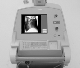
The development of mobile DR units (Fig. 11.12) with amorphous silicon has enabled the instantaneous viewing of images (typical ‘exposure-to-view’ time = 5 s), whilst being remote from the X-ray department. The advent of DR imaging has also removed the necessity for traditional chemical processors and enhanced the storage/transportation of images. Fundamental image viewing and manipulation may be achieved using a touch screen encompassed within the mobile unit.
With the near instant availability of digital images and the ability to post-manipulate at the site of exposure, additional pressures are being placed upon practitioners to provide information in order to ensure effective patient management. It is imperative that practitioners ensure the focus primarily relates to the welfare of the patient during portable examinations, whilst appreciating technology advancements.
FLUOROSCOPY EQUIPMENT
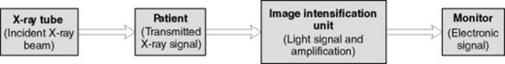
The process of converting an incident X-ray photon into an electrical signal involves a number of stages within a conventional image intensification unit. This process is depicted in Figure 11.13 and is performed in fluoroscopy and mobile units, which employ a ‘drum’ type structure aligned to an X-ray tube.
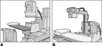
The practitioner may encounter two different types of fluoroscopy unit within the imaging department. These are under- or overcouch units (Fig. 11.14). Undercouch fluoroscopy units are designed with the X-ray tube unit underneath the imaging table and are the most popular within imaging departments. With undercouch units, the image intensification unit incorporates a handheld movement unit, allowing the practitioner to move the unit over the patient. A lead rubber protective skirt minimises the amount of primary and scattered radiation reaching the operator. Overcouch units only permit limited movement, owing to the X-ray tube being positioned over the patient, but are useful for examinations with certain patient groups, such as paediatrics.
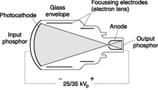
The basic purpose of an image intensification unit is to convert a weak input signal into a strong output signal within a glass vacuum environment. This conversion process begins at the input phosphor screen within the image intensification unit, which converts the incident X-ray photons into light signals. Traditionally, caesium iodide (in the form of rod shaped crystals) has been used for this purpose, as it possesses high absorption properties and is therefore able to ‘stop’ the high-energy X-ray photons. The caesium iodide crystals are supported on a glass plate and the emitted light is absorbed by a photocathode device and subsequently converted into a weak electrical signal. The number of emitted photoelectrons is proportional to the initial brightness of the input screen.8
The weak electrical signal is attracted to the output end of the image intensification unit (anode) by applying a potential difference across the input and output ends of the unit. This is similar to an X-ray tube, but the potential difference is much smaller in an image intensification unit (Fig. 11.15). The initial weak electrical signal is increased by the use of focussing electrodes, which are negatively charged and repel the electrons (which are also negatively charged). This has the effect of condensing the electrical signal, which eventually reaches the output phosphor.
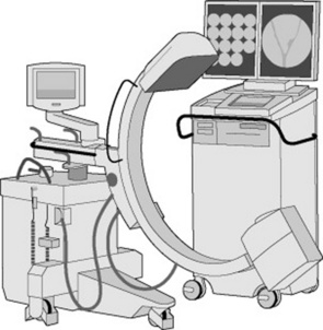
The fixed relationship between the X-ray tube and image intensification unit requires the patient to be positioned for certain projections. However, with the advent of modern C-arm design fluoroscopy units and the use of ultra-thin carbon fibre tabletops, the imaging unit may be positioned around the patient and can also be used for special projections, such as lateral decubitus images. The C-arm fluoroscopy design has been utilised in the theatre environment for many years and mobile image intensification units provide an essential service for various examinations, such as orthopaedic operations and surgical procedures. Advancements in technological design have provided operators with ‘flat panel’ image intensification units (Fig. 11.17) to replace those in the traditional ‘drum’ style. These incorporate amorphous silicon and so are similar to technology encountered in direct capture general radiography units. Such units are true digital systems, converting the incident X-ray photons into an electrical signal.
All modern mobile image intensification units employ a high frequency generator power supply and provide the operator with a wide range of exposure manipulation features, which may be rapidly adapted to suit the radiological procedure. The nominal output ranges vary according to manufacturer but typical values range from 3 to 8 kW.1 Such values are lower than traditional fluoroscopy units; however, image quality is not compromised on modern digital units. Most modern systems also employ dual focal spot sizes (typically 0.6 and 1.4 mm), which are automatically adjusted according to the type of examination being performed. A broad filament is employed when high demands are placed upon the unit to provide greater amounts of X-rays. Although a number of design features have been developed on mobile image intensification units, the majority of fundamental systems still appear to house stationary anodes.
Manual handling issues are becoming of great importance, with many studies demonstrating the risk incurred to their musculoskeletal system by healthcare professionals when undertaking their daily working practices.6 Hospital trusts nationwide are now incorporating mandatory manual handling training to promote safe working practices in an attempt to protect their staff.
The majority of modern image intensification systems encompass a wide range of image manipulation features, which commonly include virtual collimation (which permits the operator to collimate the last obtained frame in preparation for the next exposure), image rotation (virtual), zoom, flip, edge enhancement, image subtraction and a wide range of contrast and brightness tools. Advanced tools such as measurement scales, fluoroscopy reply (i.e. dynamic imaging), road mapping, noise reduction and image reversal features are also common on most systems.
With regards to radiation protection, all fluoroscopy equipment contains a number of devices similar to those found on general X-ray units, such as DAP meters. Some fluoroscopy procedures may be lengthy (e.g. tibial nailing) and consequently possibly require long screening times. It is therefore imperative that dose saving features are an essential feature on any modern image intensification unit and encompass a number of ergonomic features to enable the production of high quality images.1 The use of a ‘pulsed’ stream of electrons across the X-ray tube generates a non-continuous stream of photons, which are subsequently incident upon the patient. Pulsing technology is available on all modern image intensification equipment and should be employed whenever the operator is positioning the patient or obtaining a check image (e.g. k-wire examination in theatre). Continuous beam transmission gives higher quality images at a higher dose whereas pulse imaging gives a lower dose, but as a consequence, image quality is compromised. In some situations the images gained are of high enough quality as to negate the need for postoperative films, thus reducing dose to the patients. Some degradation to image quality may occur as a result of pulsing techniques; however modern systems provide some form of compensatory factor in an attempt to preserve image quality.
CARE OF EQUIPMENT
SECONDARY RADIATION GRIDS
Grids are a highly effective way of reducing the amount of scattered radiation reaching the image receptor (Fig. 11.18). Grids are made of strips of lead (or other attenuating material) interspaced with a radiolucent material, such as aluminium or carbon plastic fibres. The attenuating material will intercept the scattered radiation before it reaches the film, increasing the quality of the image. Up to 97% of scattered radiation can be removed through the use of a grid.
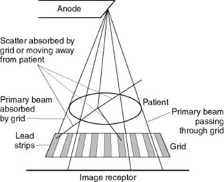
Figure 11.18 Function of a grid absorbing scattered radiation whilst allowing the useful transmitted beam to pass through.
Grids fall into a number of different categories describing their construction.
TERMS USED WITH GRIDS
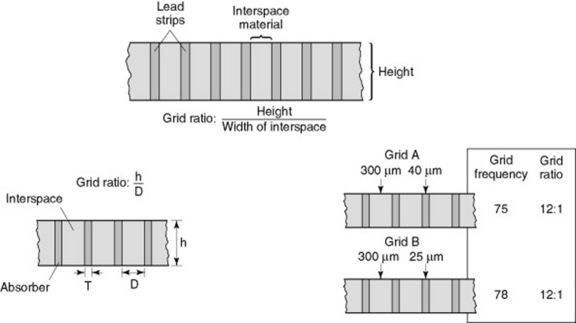
Grid ratio
The grid ratio describes the ratio of the grid height to the width of the interspace material (Fig. 11.19). Grid ratios range from 4:1 to 16:1. High-ratio grids remove more scattered radiation, increasing the radiographic contrast, and are ideal for high kV examinations. Low ratio grids are used for mammography examinations where a typical ratio value is 5:1.
1 Siemens Medical Solutions. Technical product information. On-line. Available http://www.medical.siemens.com then select UK and search for Multix swing technical info. 8 February 2008
2 Kings Centre for the Assessment of Radiological Equipment – SafeSpecs. 2004. On-line. Available http://www.kcare.co.uk/safespecs.htm. 23 January 2008
3 Bushong SC. Radiologic science for technologists: physics, biology and protection, 7th edn. London: Mosby, 2001.
4 College of Radiographers. Statements for professional conduct. London: College of Radiographers, 2002.
5 Siemens Medical Solutions. Product information – Multix Compact K system. Germany: Siemens Medical Solutions, 2002.
6 Department of Health. The Ionising Radiation (Medical Exposure) Regulations 2000. London: Department of Health, 1999.
7 General Electrics. Radiography – Proteus XR/a information. 2004. On-line. Available http://www.gemedicalsystemseurope.com/euen/rad/xr/radio/products/msxpro_eou.html. 23 January 2008
8 Munkert A. The first fully digital C-Arm – 21st century mobile X-ray imaging. Medical Imaging in Bavaria. 2003:1-7.


