CHAPTER 4 Diagnostic Arthroscopy for the Ankle and Subtalar Joints
The ankle is a highly constrained joint composed of complex, curved articular surfaces that are stabilized by ligaments with various degrees of laxity. These anatomic constraints make arthroscopy of the ankle joint more difficult than in larger joints such as the knee and shoulder. Early attempts to perform arthroscopy of the ankle joint were met with various degrees of success. In a 1931 cadaver study, Burman suggested that the ankle joint “… is not suitable for arthroscopy.”1
Arthroscopists in the 1980s began to apply modern techniques to instrumentation of the ankle and defined the basic portals with which to approach the joint.2–4 Since then, two technical advances have facilitated routine performance of ankle arthroscopy for diagnosis and surgical procedures. First, the development of high-quality, small-diameter arthroscopes has allowed instrumentation of the ankle with increased ability to visualize the entire joint while decreasing the likelihood of iatrogenic articular cartilage injury. Second, techniques have been developed for noninvasive joint distraction to facilitate instrument passage and decrease joint injury.5 Without distraction, it is often impossible to visualize the central and posterior compartments of the joint from the anterior portals. Early attempts to distract the joint used pins placed into the tibia and calcaneus that were connected to a distractor device similar to an external fixator. The use of these devices was associated with significant complications, including pin tract infection and neurovascular injury.6 Elimination of these complications while effectively distracting the joint with noninvasive strap distraction is a major advantage, and invasive ankle joint distraction is no longer recommended.
PATIENT POSITIONING
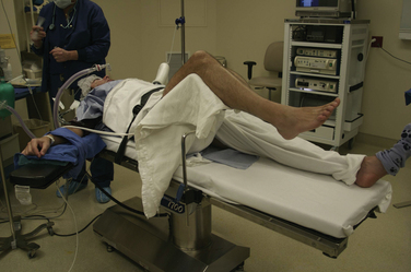
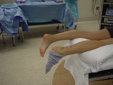
The patient is placed supine on the operating table with the hip and knee flexed and supported by a well-padded leg holder (Fig. 4-1). I prefer a leg holder with a long thigh segment and short knee segment to diffuse the distraction force over the wide area of the thigh rather than concentrating the force in the popliteal space and potentially causing obstruction to venous outflow. Sterile drapes are applied after skin preparation.
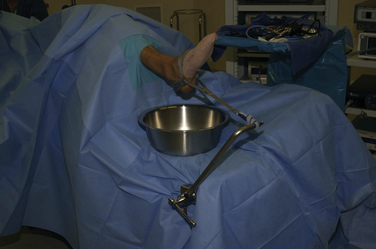
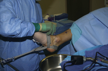
A sterile clamp is attached to the operating table side rail over the sheets, and a bar is fixed to the clamp. The noninvasive ankle distractor strap is placed around the hindfoot and midfoot and connected to the bar using a segment of sterile two-sided Velcro. This distraction setup allows the ankle and foot to rest in a plantigrade position while retaining the ability to move the ankle in dorsiflexion and plantar flexion intraoperatively (Fig. 4-2).
Invasive distraction is not required for standard ankle arthroscopy. It poses unnecessary risks to neurovascular structures, along with risks of infection and stress fracture.
PORTAL CREATION
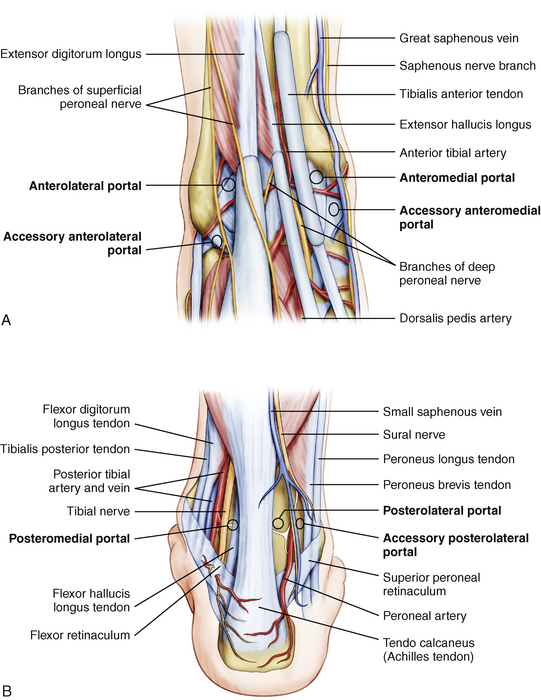
The three standard working portals for ankle arthroscopy are the anteromedial portal, the anterolateral portal, and the posterolateral portal (Fig. 4-3). The anterocentral portal was used in the early days of ankle arthroscopy because of the purported benefit of increased visualization in the central compartment. However, this portal placement poses significant risk of injury to the deep peroneal nerve and the dorsalis pedis artery. The use of small joint arthroscopes and noninvasive joint distraction obviates the use of this portal for ankle arthroscopy.
The first portal created should be the anteromedial portal. In most patients, there is an indentation in the anteromedial articular surface of the distal tibia, known as the notch of Harty, that facilitates passage of instruments across the ankle joint from medial to lateral aspects. The surgeon palpates the tibialis anterior tendon and inserts an 18-gauge needle into the joint immediately adjacent to the tendon’s medial border (Fig. 4-4). As the needle enters the joint, the surgeon notices the sound of air entering the joint, which also allows the ankle to be distracted more easily. Needle placement is adjusted proximally or distally until the position that allows easiest passage across the joint is identified as the optimal location for the portal. The cannula is introduced through this portal, and the 2.7-mm arthroscope is introduced into the joint.
With the arthroscope in the anteromedial portal, the posterolateral portal is created under direct visualization. The portal is located adjacent to the lateral border of the Achilles tendon and approximately 1 to 2 cm distal to the anterior portal so that an upwardly angled 18-gauge needle passes into the joint beneath the posterior syndesmotic ligament complex and accommodates the posterior curvature of the talar dome (Fig. 4-5). Another 2.7-mm cannula is placed and functions as a dedicated inflow cannula attached to an arthroscopic fluid pump.
PEARLS& PITFALLS
PEARLS
DIAGNOSTIC ARTHROSCOPY
Ferkel has emphasized the importance of an organized approach to diagnostic ankle arthroscopy with a 21-point examination that starts with the anteromedial approach, then uses the anterolateral approach, and concludes with direct posterior viewing from the posterolateral portal.7 Depending on the pathology, initial visualization of the joint may be impaired by hypertrophic synovium or bony exostoses, and limited débridement may be required at the start of the case. It is important to débride any hypertrophic synovium with a mechanical shaver, keeping the blade directed away from the relatively thin capsule of the anterior joint to avoid inadvertent injury to the anterior neurovascular structures while also avoiding injury to the joint surfaces. Bipolar intra-articular cautery facilitates hemostasis when performing the procedure without tourniquet inflation.
The tip of the medial malleolus is visualized from the anteromedial portal along with the deep deltoid ligament spanning the space between the malleolus and the talus (Fig. 4-6). A probe is introduced from the anterolateral portal to palpate structures with the arthroscope in the anteromedial portal. The surgeon then directs the arthroscope up the medial gutter (Fig. 4-7) and into the tibiotalar joint through the notch of Harty (Fig. 4-8). At this point, the arthroscope usually can be maneuvered in a posterolateral direction across the dome of the talus, affording visualization of the entire dome of the talus and the posterior joint structures (Fig. 4-9).
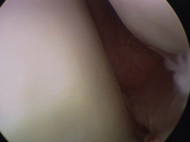
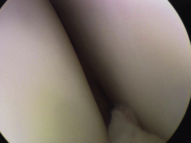
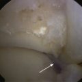
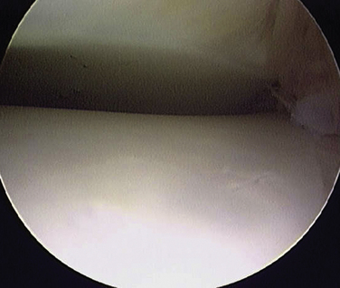
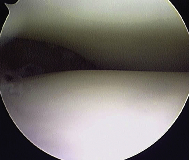
FIGURE 4-7 Arthroscopic view from the anteromedial portal shows the medial gutter of the right ankle.
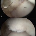
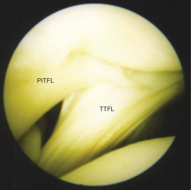
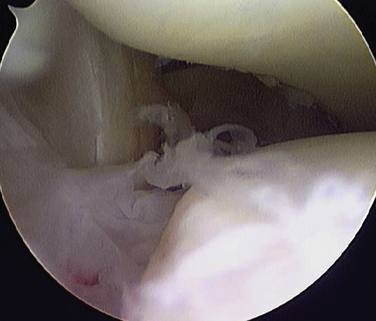
The interosseous ligament complex is identified posteriorly (Fig. 4-10). These ligaments display a variable anatomy and have been described differently in anatomic dissection studies. Ferkel has described three major ligament components.8 Superiorly, the broad posterior-inferior tibiofibular ligament represents the most distal end of the syndesmosis and its most distal fibers can be seen intra-articularly as the most superior component of the complex coursing from superior and medial to inferior and lateral aspects. Beneath this ligament is the less robust transverse tibiofibular ligament, which attaches to the posterior fibular tubercle on the fibula and to the posterior portion of the distal tibial articular surface, spanning to the medial malleolus. The tibial slip is the most inferior of the posterior interosseous structures. Golano and colleagues have described the posterior ligament anatomy to include the posterior-inferior tibiofibular ligament, which is also called the tibial slip.9 The transverse ligament was defined as the deep component of the posterior-inferior tibiofibular ligament. The flexor hallucis longus tendon may be seen as a vertically oriented structure in the posterior ankle compartment when the capsule is thin, and this structure is made more prominent by flexing and extending the great toe.
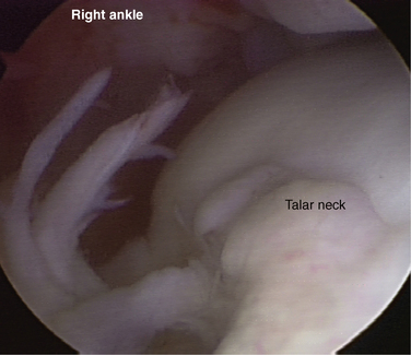
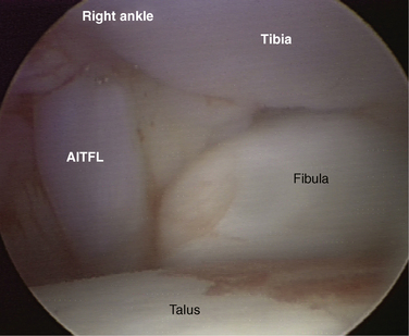
Depending on the degree of inherent joint laxity, it may not be possible to maneuver the arthroscope directly across to the lateral side of the joint, but the lateral joint structures can be visualized by directing the arthroscope’s viewing angle laterally (Fig. 4-11). The structures to be identified are the lateral dome of the talus, the distal tibiofibular joint, and the soft tissues of the syndesmosis. The arthroscope is then gently withdrawn, revealing the anterior tibia, which should be carefully examined for the presence of bony exostosis (Fig. 4-12). The view of the anterior joint may be facilitated by decreasing the amount of joint distraction while dorsiflexing the ankle to allow the anterior capsule to distend. The arthroscope’s viewing angle is then directed along the neck of the talus to evaluate the capsular insertion on the talar neck (Fig. 4-13). As the arthroscope is directed laterally, the well-defined inferior fascicle of the anterior-inferior tibiofibular ligament is identified as a vertically oriented structure connecting the tibia and fibula (Fig. 4-14).
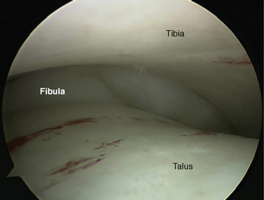
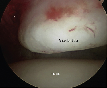
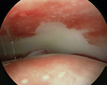
FIGURE 4-12 Arthroscopic view from anteromedial portal shows the distal tibial articular surface of the right ankle.
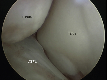
The arthroscope is directed into the lateral gutter and then down to the level of the tip of the lateral malleolus (Fig. 4-15). The anterior talofibular ligament can usually be defined starting from its origin on the anterior-inferior fibula and curving to insert on the talus.
The arthroscope is then switched to the anterolateral portal, and a diagnostic examination is performed from this approach starting at the tip of the lateral malleolus, which can usually be viewed more completely from this approach. In addition to the anterior talofibular ligament, the entire articular surface of the lateral gutter is evaluated from this viewpoint, and the posterior talofibular ligament often can be seen at the posterior extent of the gutter. The arthroscope is then directed up the lateral gutter and into the anterolateral joint to visualize the syndesmosis, distal fibula, lateral tibia, and lateral dome of the talus. All structures visualized from the anteromedial portal are evaluated from the anterolateral perspective for complete assessment.
SUBTALAR JOINT ARTHROSCOPY
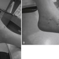
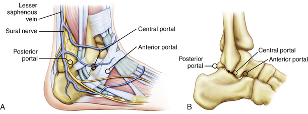
The anterolateral portal is placed approximately in the soft spot of the sinus tarsi, about 2 cm anterior and 1 cm distal to the tip of the fibula (Fig. 4-16). The posterolateral portal is placed approximately 2 cm posterior and 1 cm proximal to the tip of the fibula, which is lateral to the border of the Achilles tendon. If the subtalar arthroscopy is performed after ankle joint arthroscopy, the posterolateral portal used for the ankle can be redirected into the subtalar joint. The central portal is located just distal and inferior to the lateral malleolus tip. This portal is immediately anterior to the peroneal tendon sheath.
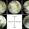
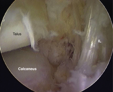
The joint is examined from the anterior view while placing a probe into the central portal. The arthroscope is introduced posterior to the interosseous ligament and advanced as far medial as possible to visualize the deep portion of the ligament and medial articular surface of the posterior subtalar joint (Fig. 4-17). As the arthroscope is slowly withdrawn, the more superficial portion of the ligament and the anterolateral margin of the posterior subtalar joint are examined (Fig. 4-18). As the arthroscope is manipulated into the lateral gutter, rotating it for viewing and keeping the joint line visible as the corner is rounded, the lateral talocalcaneal ligament is the first ligament capsular condensation observed (Fig. 4-19). Proceeding slightly more posteriorly, the operator can see the location of the calcaneofibular ligament.
In some joints, the arthroscope can be advanced from the anterolateral portal further into the lateral gutter to the posterolateral recess (Fig. 4-20). As the viewing angle is turned toward the joint, the articular surface of the posterior process of the talus, or the os trigonum if present, can be seen. Turning the viewing angle toward the capsule laterally reveals the posterior talocalcaneal ligament.
If the arthroscope cannot be advanced into the posterolateral recess from the anterolateral portal, the arthroscope is switched to the posterior portal to achieve visualization of the structures previously described. In a relatively lax ankle, the arthroscope can be advanced across the joint, and the interosseous ligament can be examined from this posterior view. The examination should start in the lateral gutter. The arthroscope then is withdrawn carefully as the posterolateral corner is rounded and the central and the medial aspects of the posterior subtalar joint are examined. If feasible, the arthroscope is advanced into the posteromedial gutter and then anteriorly to visualize as much of the medial articular surface as possible.
POSTERIOR ANKLE AND SUBTALAR ARTHROSCOPY
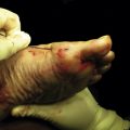
The patient is placed prone on the operating table with the foot and ankle extended slightly past the end of the table and supported with a small bolster (Fig. 4-21). If distraction is necessary, a soft tissue distractor may be placed as for routine anterior arthroscopy and attached to the surgeon, who can apply traction when necessary by leaning backward. However, much posterior pathology can be approached without distraction, including os trigonum, posterior bony or soft tissue impingement, pathology of the flexor hallucis longus tendon, and posterior articular pathology of the talus or calcaneus.
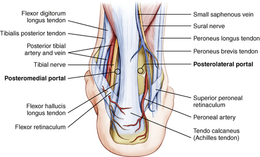
Portals are placed immediately adjacent to the medial and lateral borders of the Achilles tendon at approximately the level of the tip of the fibula (Fig. 4-22). The nick and spread technique is used to avoid injury to superficial neurovascular structures. The standard 4-mm arthroscope can be used for posterior ankle arthroscopy.
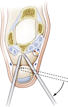
The arthroscope cannula with a blunt trocar is introduced into the lateral portal and directed toward the great toe until bone is palpated. The arthroscope is introduced into this cannula. Inflow is placed under low-pressure and low-flow parameters, but there is no actual space in which to see; only the fat is visible immediately posterior to the joint. The 3.5-mm shaver is introduced from the medial portal at a perpendicular angle to the arthroscope, and it is advanced until it makes contact with the arthroscope’s cannula. The shaver is then directed along the cannula until it reaches the level of the arthroscope’s tip (Fig. 4-23). Initial shaving is performed with the open end of the shaver directed laterally and the viewing angle of the arthroscope directed medially. In this fashion, the blade is less likely to be directed toward the flexor hallucis longus tendon and the neurovascular structures medial to it. With minimal shaving, a space is created, and the flexor hallucis longus is identified.
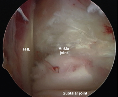
After the tendon is identified, it is protected from the surgical instruments, and all dissection is directed lateral to the tendon (Fig. 4-24). A capsulectomy is performed, revealing the ankle joint above and the subtalar joint below. The posterior process of the talus, or the os trigonum if present, is identified along with the attachment of the posterior talofibular ligament (Fig. 4-25). A bipolar electrocautery device is useful to achieve hemostasis and to perform accurate dissection of soft tissue from bone. Pathology in both joints can be addressed from this approach, and operative arthroscopy is described in Chapter ••.
CONCLUSIONS
The posterior ankle and subtalar joints can be viewed from the direct posterior approach using the technique of van Dijk. This approach is particularly useful for the treatment of posterior ankle impingement, os trigonum syndrome, posterior osteochondral defects of the ankle and subtalar joint, and pathology involving the flexor hallucis longus tendon.
1. Burman MS. Arthroscopy or the direct visualization of joints. an experimental cadaver study, J Bone Joint Surg Am. 131931 669-695.
2. Andrews JR, Previte WJ, Carson WG. Arthroscopy of the ankle. technique and normal anatomy, Foot Ankle. 61985 29-33.
3. Parisien JS. Diagnostic and operative arthroscopy of the ankle. technique and indications, Bull Hosp Jt Dis Orthop Inst. 451985 38-47.
4. Parisien JS, Vangsness T, Feldman R. Diagnostic and operative arthroscopy of the ankle. An experimental approach. Clin Orthop Relat Res. 1987;224:228-236.
5. Stetson WB, Ferkel RD. Ankle arthroscopy. I. Technique and complications. J Am Acad Orthop Surg. 1996;4:17-23.
6. Ferkel RD, Small HN, Gittins JE. Complications in foot and ankle arthroscopy. Clin Orthop Rerlat Res. 2001;391:89-104.
7. Ferkel RD, Scranton PE. Current concepts review. arthroscopy of the ankle and foot, J Bone Joint Surg Am. 751993 1233-1242.
8. Ferkel RD, Weiss RA. Correlative surgical anatomy. In: Ferkel RD, editor. Arthroscopic Surgery. The Foot and Ankle. Philadelphia, PA: Lippincott-Raven; 1996:85-102.
9. Golano P, Mariani PP, Rodrigues-Niedenfuhr M, et al. Arthroscopic anatomy of the posterior ankle ligaments. Arthroscopy. 2002;18:353-358.
10. Van Dijk CN, Scholten PE, Krips R. A 2-portal endoscopic approach for diagnosis and treatment of posterior ankle pathology. Arthroscopy. 2000;16:871-876.
11. Scholten PE, Sierevelt IN, van Dijk CN. Hindfoot endoscopy for posterior ankle impingement. J Bone Joint Surg Am. 2008;90:2665-2672.
12. Van Dijk CN, van Bergen CJA. Advancements in ankle arthroscopy. J Am Acad Orthop Surg. 2008;16:635-646.