Developmental abnormalities
Classification of developmental abnormalities
Developmental anomalies of the maxillofacial region are usually classified into:
Anomalies of the teeth
These include abnormalities in:
Abnormalities in structure
Abnormalities in shape
Anomalies affecting whole teeth
• Fusion – two teeth joined together from the fusion of adjacent tooth germs
• Gemination – two teeth joined together but arising from a single tooth germ
• Concrescence – two teeth joined together by cementum
• Dens-in-dente (invaginated odontome) – infolding of the outer surface of a tooth into the interior usually in the cingulum pit region of maxillary lateral incisors.
Anomalies affecting roots and/or pulp canals
• Number – additional roots, e.g. two-rooted incisors, three-rooted premolars or four-rooted molars
– Dilaceration – sharp bend in the root direction
– Taurodontism – short, stumpy roots and longitudinally enlarged pulp chambers
• Pulp stones – localized or associated with specific syndromes, e.g. Ehlers–Danlos (floppy joint syndrome)
Abnormalities in position
 and
and 
Other positional anomalies
• Transposition, two teeth occupying exchanged positions
• Wandering teeth, movement of unerupted teeth for no apparent reason (distal drift)
• Infraocclusion, second deciduous molars apparently descend into the jaws. These teeth in fact remain in their original position while the adjacent alveolar bone grows normally. As these teeth appear to submerge the original term for this positional anomaly was submersion.
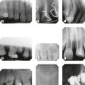
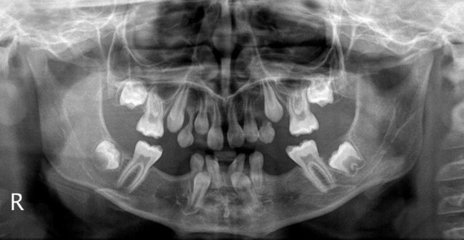
Typical radiographic appearances of the more common and important developmental abnormalities
 .
.
 .
.
 (arrowed).
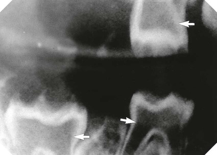
 showing the typical gnarled enamel defects of a Turner tooth (arrowed), caused by previous infection of the deciduous predecessor.
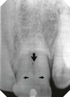
 (arrowed).
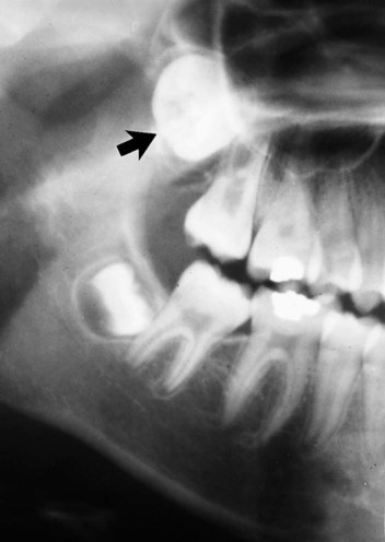
 (arrowed).
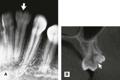
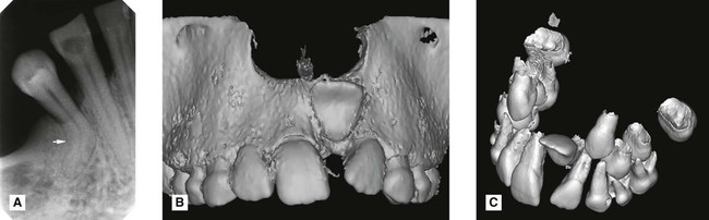
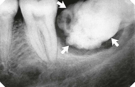
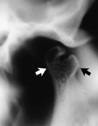
 (arrowed). B Cross-sectional cone beam CT image showing gemination of
  (arrowed).
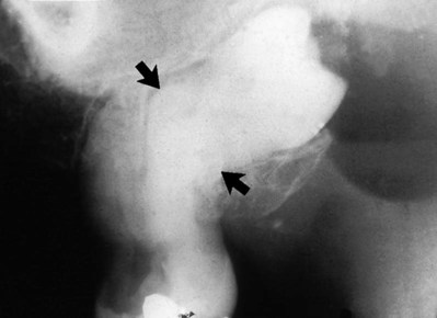
 (arrowed). Note it is not possible to be certain simply from the radiograph that
  are joined together with cementum.
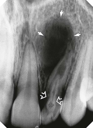
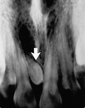
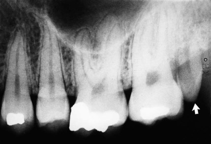
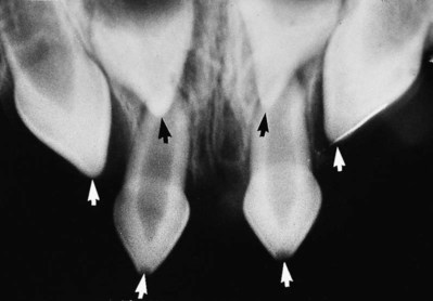
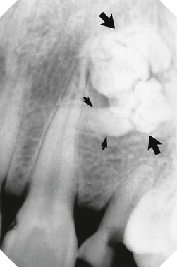
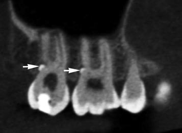
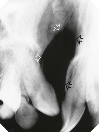
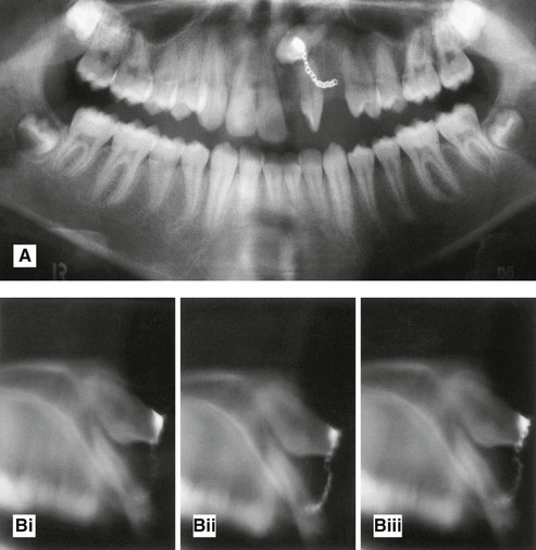
 (open arrows). There is an associated periapical area of infection (solid arrows) – a common occurrence with dens-in-dente.
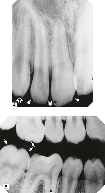
 with a near right angle bend in the root (arrowed). B Surface rendered 3-D cone beam CT image showing a dilacerated
  . C Segmented surface rendered view showing only the teeth and the same dilacerated
  .
. 
 .
.
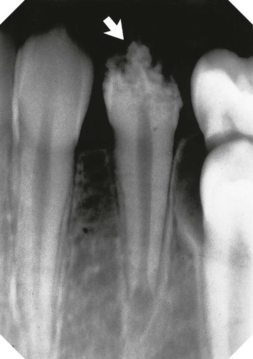
 (arrowed).
 region (arrowed).
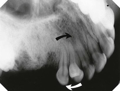
 to give
  (arrowed).
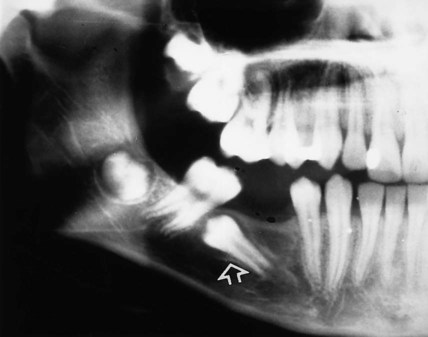
 (arrowed).
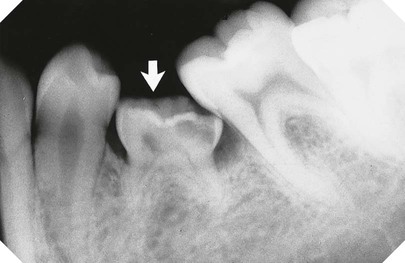
 (arrowed). Note there is no underlying second premolar.
 is absent.
Radiographic assessment of mandibular third molars
Radiographic views used
The usual radiographs used include:
Periapicals need to be of good quality. In particular, the geometric relationship of the third molar to the surrounding structures must be accurate. To satisfy this requirement, modifications to conventional radiographic techniques are often necessary, as described in detail in Chapter 9. If available, cone beam CT, described in Chapter 16, can greatly facilitate this radiographic assessment by providing images in the coronal, axial and sagittal planes.
Radiographic interpretation
The specific features that need to be identified can be divided into those related to:
Lower third molar assessment
The main features to examine include:
• The relationship of the apices with the inferior dental (ID) canal
The relationship of the apices to the ID canal
The apices of the lower third molar often appear close to the ID canal. This apparent closeness is usually due to these structures being superimposed. However, an intimate relationship does sometimes exist. The root may be grooved by the canal, or rarely, included within the developing root, as illustrated in Figs 24.38 and 24.49.
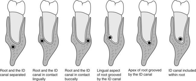
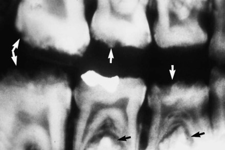
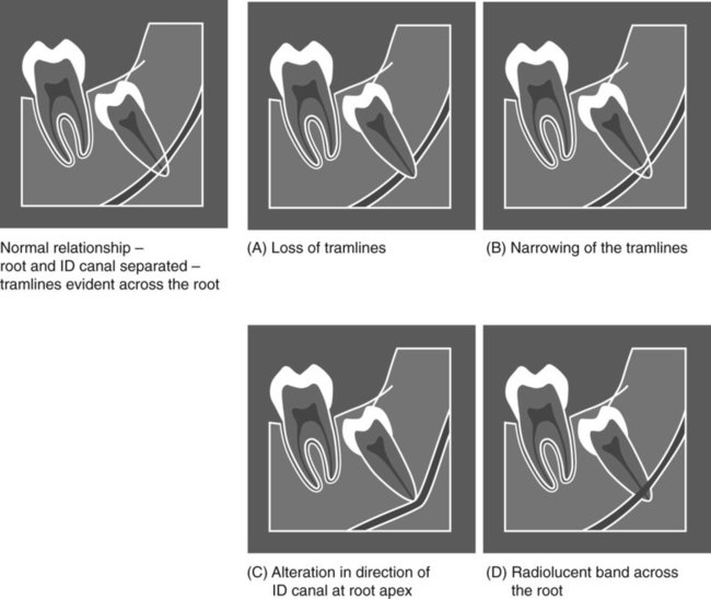
The normal radiographic appearance of the ID canal (two thin, parallel radiopaque lines – the so-called tramlines) and the variations that indicate a possible intimate relationship are shown in Fig. 24.39. These variations include:
The depth of the tooth in the alveolar bone
Two main methods are used commonly to assess tooth depth:
Winter’s lines (see Fig. 24.40)
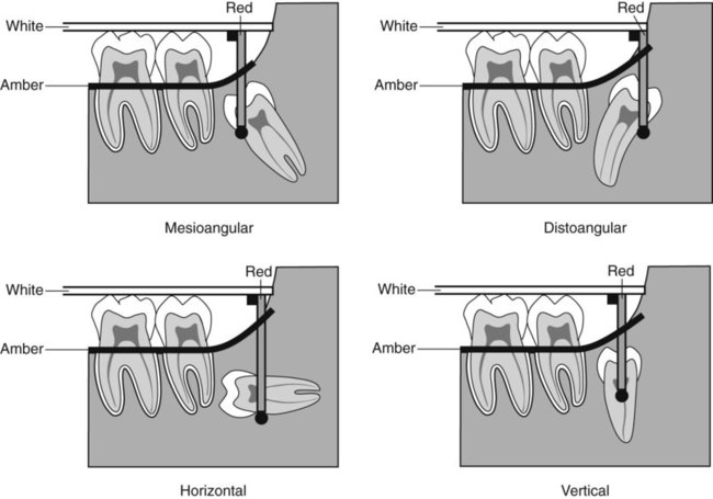
• The first or white line is drawn along the occlusal surfaces of the erupted first and second molars.
• The second or amber line is drawn along the crest of the interdental bone between the first and second molars, extending distally along the internal oblique ridge, NOT the external oblique ridge. This line indicates the margin of the alveolar bone surrounding the tooth.
• The third or red line is a perpendicular dropped from the white line to the point of application for an elevator, but is measured from the amber line to this point of application. This line measures the depth of the third molar within the mandible. (As a general rule, if the red line is 5 mm or more in length, the extraction is considered sufficiently difficult for the tooth to be removed under general anaesthetic or using local anaesthetic and sedation.)
Using the roots of the second molar as a guide (see Fig. 24.41)
This method can be summarized as follows:
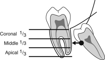
• The roots of the adjacent second molar are divided horizontally into thirds
• A horizontal line is then drawn from the point of application for an elevator to the second molar
• If the point of application lies opposite the coronal, middle or apical third, the extraction is assessed as being easy, moderate or difficult, respectively.
The buccal or lingual obliquity
• Buccal obliquity – the crown of the wisdom tooth is inclined towards the cheek
• Lingual obliquity – the crown of the wisdom tooth is inclined towards the tongue.
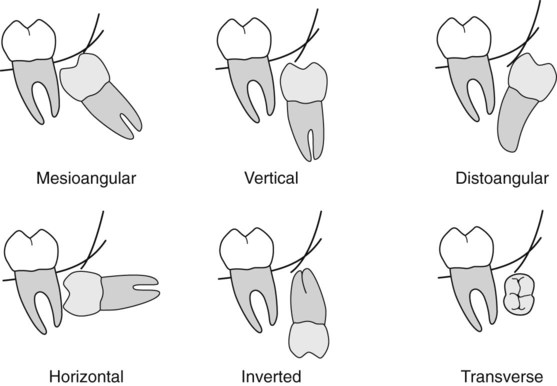
The lie of the tooth in the horizontal plane cannot be determined accurately from a periapical radiograph. The views of choice for this assessment include:
Assessment of the surrounding bone
The main features to examine include:
• The anteroposterior position of the ascending ramus, to determine access to the tooth and the amount of overlying bone
All these points relating to the third molar, the second molar and the surrounding tissues are considered together, and a conclusion drawn as to the overall difficulty of the proposed extraction.
Examples of unerupted lower third molars, illustrating some of the more important radiographic features, are shown in Figs 24.42–24.49.
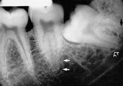
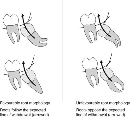
 . Note the unfavourable root curvatures (black arrow), the uninterrupted upper tramline of the inferior dental canal (open white arrow) and the conically shaped root of
  (solid white arrows).
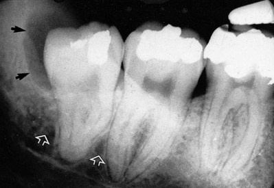
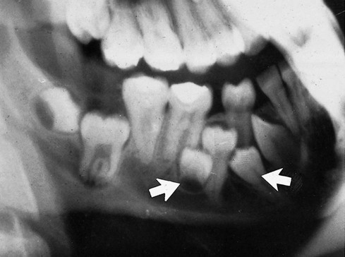
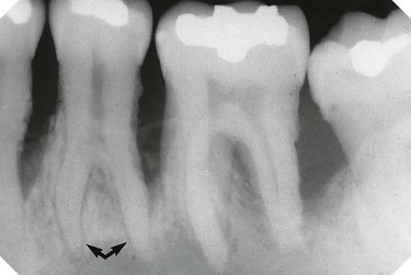
 . Note the favourable conically shaped roots, the uninterrupted upper tramline of the inferior dental canal (open white arrows) and the radiolucent area distal to the crown (black arrows) caused by the residual follicle.
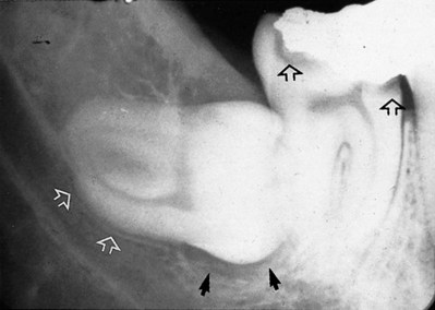
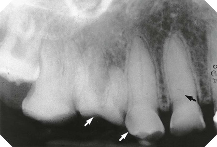
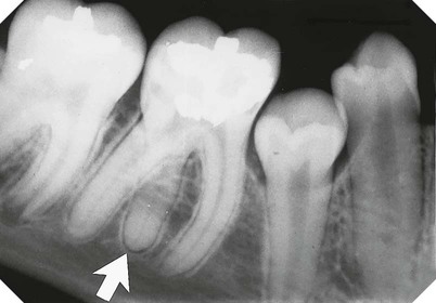
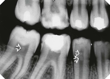
 . Note the pincer-shaped roots and their indentation of the upper margin of the inferior dental canal (open white arrows), radiolucency beneath the crown (solid black arrows) caused by the follicle. In addition, note the caries lesions in
  (open black arrows).
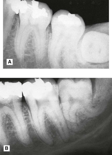
 . The crown is viewed end-on. Note that the bucco/lingual obliquity of the tooth cannot be determined from this radiograph. B Vertically positioned
  with very unfavourable root curvatures.
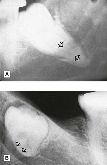
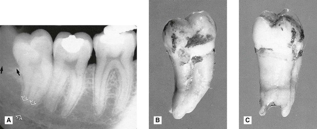
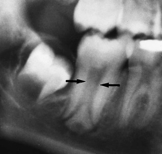
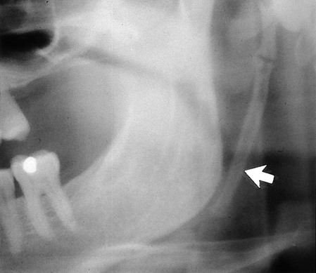
 . Note the extensive area of bone resorption distal to the crown (black arrows) caused by previous pericoronal infection. There is a radiolucent band across the tooth apex which is also hazy in outline (open white arrows) caused by the inferior dental canal, implying an intimate relationship. B The extracted
  viewed as in the radiograph from the buccal aspect. C The extracted tooth viewed from the distal aspect showing clearly the notching of the tooth apex by the inferior dental canal. This explains the radiolucent band across the apex – there is simply less tooth tissue in this zone, because of the position of the inferior dental canal.
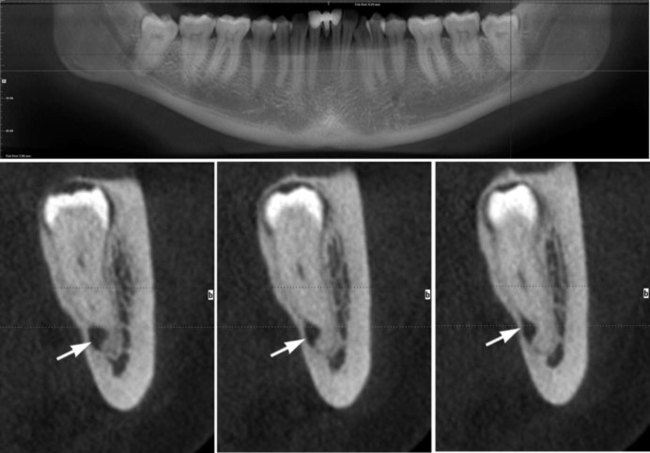
 (arrowed).
Radiographic assessment of unerupted maxillary canines
• To determine the size and shape of the canine and any related disease, including possible resorption of the adjacent lateral incisor.
Assessment of the canine size and shape and the surrounding tissues
Radiographic views used (see Fig. 24.50)
The usual radiographs used include:
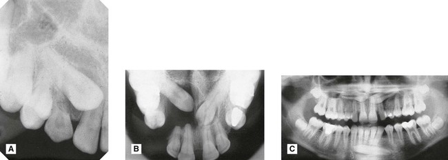
A Periapical showing unerupted
 with retained C.
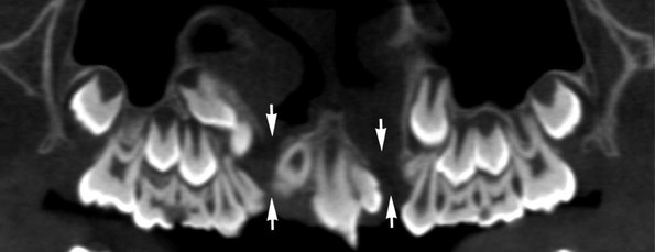
B Upper standard occlusal showing both upper canines unerupted, a dentigerous cyst associated with
 , extensive destruction of the alveolar bone and resorption of
C Panoramic radiograph showing unerupted
 and
and  .
.
Assessment of the position of the canine – localization
The principle of parallax
Parallax is defined as the apparent displacement of an object because of different positions of the observer. In other words, if two objects, in two separate planes, are viewed from two different positions, the objects will appear to move in different directions in relation to one another, from one view to the next, as shown in Fig. 24.51.
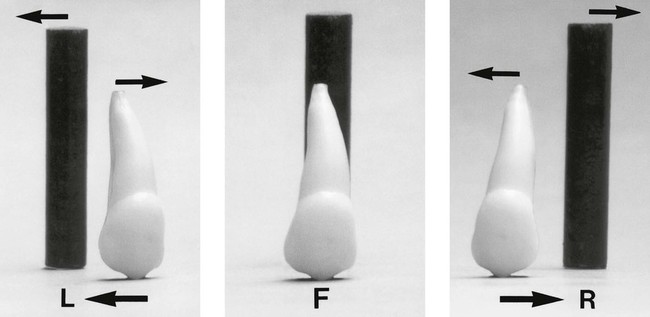
• If the canine is palatally positioned, it will appear to have moved in the same direction as the X-ray tubehead.
• If the canine is buccally positioned, it will appear to have moved in the opposite direction to the X-ray tubehead.
• If the unerupted canine is in the same plane as the incisors, i.e. in the line of the arch, it will appear not to have moved at all.
A useful acronym to remember the movements of parallax is SLOB, standing for:
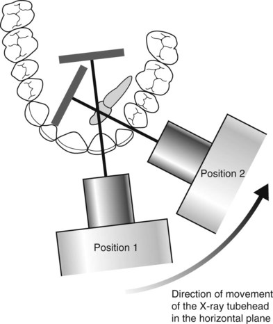
Parallax in the horizontal plane
The movement of the X-ray tubehead is in the horizontal plane, for example:
• Two periapicals – one centred on the upper central incisor and the other centred on the canine region, as shown in Fig. 24.52.
• An upper standard occlusal, centred in the midline plus a periapical or an upper oblique occlusal, centred on the canine region.
Examples are shown in Figs 24.53–24.55.
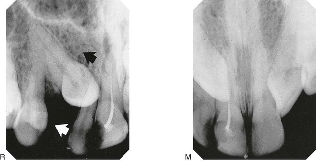
 to the incisors – M in the midline and R from the right. The X-ray tubehead (white arrow) and the canine (black arrow) appear to have moved in the same direction. The canine is thus palatally positioned.
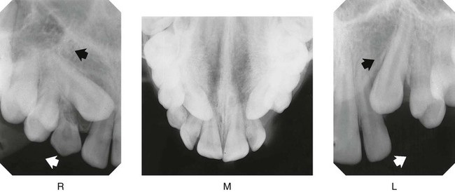
1. Examine the midline view radiograph (M), centred on the upper central incisors. The tip of the RIGHT canine appears opposite the root canal of  ; the tip of the LEFT canine appears opposite the mesial aspect
  .
.
2.Examine radiograph (R), the periapical centred on the RIGHT canine region (i.e. the X-ray tubehead has been moved distally in the direction of the white arrow). The tip of the canine appears opposite the mesial aspect of  . Therefore, it appears to have moved distally in the direction of the black arrow, i.e. in the same direction as the X-ray tubehead was moved.
3.Examine radiograph (L), the periapical centred on the LEFT canine region. The tip of the canine appears opposite the root canal of  Again both the X-ray tubehead (white arrow) and the canine (black arrow) appear to have moved in the same direction.
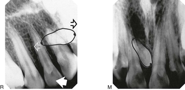
1. Examine the mid-line radiograph (M). The tip of the mesiodens’ crown appears opposite the mesial aspect of  while its apex appears opposite the root canal of
  .
.
2.Examine the periapical centred on the RIGHT canine region (R). The tip of the mesiodens crown appears opposite the root canal of  , while its apex appears opposite the mesial aspect of
  .
.
3.The X-ray tubehead was moved distally in the direction of the large white solid arrow.
4.The crown of the mesiodens appears to have moved mesially (black open arrow), i.e. in the opposite direction to the tubehead. It is thus buccally placed.
5.The apex appears to have moved in the same direction (white open arrow) as the tubehead and is thus palatally placed.
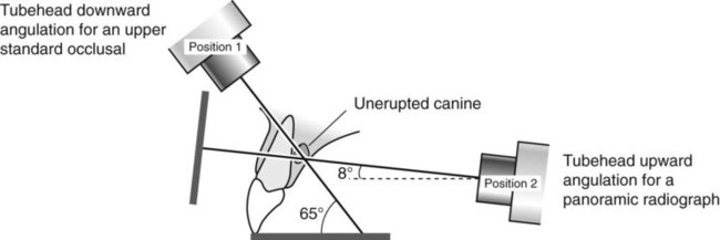
Parallax in the vertical plane
The movement of the X-ray tubehead is in the vertical plane, for example:
• A panoramic radiograph – the X-ray beam is aimed upwards at 8° to the horizontal
• An upper standard occlusal – the X-ray beam is aimed downwards at 65°–70° to the horizontal, as shown in Figs 24.56 and 24.57.
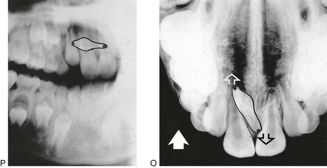
1. Examine the panoramic radiograph (P) taken with the tubehead aimed upwards at 8° to the horizontal. The tip of mesiodens’ crown appears opposite the neck of the lateral incisor, while its apex appears opposite the root of  .
.
2.Examine the occlusal radiograph (O) taken with the tubehead aimed downwards at 65° to the horizontal. The tip of the mesiodens’ crown now appears beyond the apex of  , while its apex appears opposite the crown of
  .
.
3.The X-ray tubehead has moved vertically upwards from view (P) to view (O) in the direction of the solid white arrow.
4.The crown of the mesiodens appears to have moved in the same direction (white open arrow) and is thus palatally placed.
5.The apex of the mesiodens appears to have moved in the opposite direction (black open arrow), and is thus buccally placed.
Note: This combination of views is used frequently in orthodontics, when patients with unerupted canines are usually assessed. Use of these films to their full potential may obviate the need for further films merely to localize the unerupted canines.
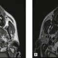
Localization using cross-sectional tomography and cone beam CT
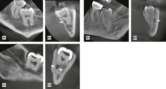
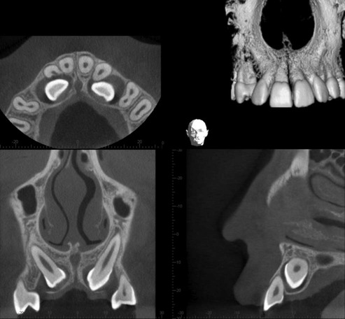
Localization of unerupted developmental anomalies using these more advanced imaging modalities is straightforward (see Chs 16 and 18), if the facilities are available. They allow visualization of the unerupted abnormality in different planes. There is no need to use the principles of parallax. Two examples are shown in Figs 24.58 and 24.59.
To access the self assessment questions for this chapter please go to www.whaitesessentialsdentalradiography.com