Cystourethroscopy
Alfred E. Bent  Geoffrey W. Cundiff
Instrumentation
The rigid urethroscope is a modification of the cystoscope, designed exclusively for evaluation of the urethra (Fig. 123–1). Because it is primarily a diagnostic instrument, it does not have a bridge. The telescope is shorter and has a 0° viewing angle, which provides a circumferential view of the urethral lumen as the mucosa in front of the urethroscope is distended by a distention medium. The 0° lens is essential for adequate urethroscopy. The urethroscope sheath is designed to maximize distention of the urethral lumen. Sheaths are available in 15F and 24F calibers. If tolerated, the larger sheath is useful because it provides the best view of the urethral lumen by providing more rapid fluid flow for maximal distention. It also allows easier visibility of any abnormalities such as urethral diverticula.
The rigid cystoscope has three components: the telescope, the bridge, and the sheath (Fig. 123–2A through C). Each component serves a different function and is available with various options to facilitate its role under different circumstances. The telescope transmits light to the bladder cavity, as well as an image to the viewer. Telescopes designed for cystoscopy are available with several viewing angles, including 0° (straight), 30° (forward oblique), 70° (lateral), and 120° (retroview). The different angles facilitate the inspection of the entire bladder wall. Although the 0° lens is essential for adequate urethroscopy, it is insufficient for cystoscopy. The 30° lens provides the best view of the bladder base and posterior wall, and the 70° lens permits inspection of the anterior and lateral walls. The retroview of the 120° lens is not usually necessary for cystoscopy of the female bladder but can be useful for evaluating the urethral opening into the bladder. In diagnostic cystoscopy, the 30° telescope usually is sufficient, although a 70° telescope may be required in the presence of elevation of the urethrovesical junction, such as after colposuspension procedures. The angled telescopes have a field marker, which is a blackened notch on the outside of the visual field opposite the angle of the deflection that helps facilitate orientation. The cystoscope sheath provides a vehicle for introducing the telescope and distending media into the bladder cavity. Sheaths are available in various calibers, ranging from 17F to 28F for use in adults. When placed within the sheath, the telescope, which is a 15F instrument, only partially fills the lumen, leaving an irrigation working channel. The smallest sheath is better tolerated for diagnostic purposes, whereas usually at least a 19F sheath is required for placement of instruments into the irrigation working channel. The proximal end of the sheath has two working ports: one for introduction of the distending media and another for removal. The distal end of the cystoscope sheath is fenestrated to permit use of instrumentation in the angled field of view. It is also beveled, opposite the fenestra, to increase the comfort of the introduction of the cystoscope into the urethra. The bridge serves as a connector between the telescope and sheath and forms a water-tight seal. It also may have one or two ports for introduction of instruments into the irrigation working channel. The Albarran bridge is a variation with a deflector mechanism at the end of the inner sheath. When placed in the cystoscope sheath, the deflector mechanism is located at the distal end of the inner sheath within the fenestra of the outer sheath. In this location, elevation of the deflector mechanism assists the manipulation of instruments within the field of view.
Unlike the rigid cystoscope, the flexible cystoscope combines the optical systems and irrigation working channel in a single unit (Fig. 123–2D). The coated tip is 15F to 18F in diameter and 6 to 7 cm in length; the working unit makes up half the length. The flexibility of the fibers permits incorporation of a distal tip-deflecting mechanism, controlled by a lever at the eyepiece that will deflect the tip 290° in a single plane.
Any light source that provides adequate illumination via a fiberoptic cable is sufficient. A high-intensity xenon light source is often recommended for use in video monitoring or photography, but with recent innovations, the newest cameras require less light. Video recording and still-picture capabilities are very important for documentation, as well as teaching. Three types of distention media are available: nonconductive fluids, conductive fluids, and gases. Cystourethroscopy is feasible with carbon dioxide, but most practitioners prefer the use of water or saline to distend the bladder and urethra. A liquid medium prevents the carbon dioxide from bubbling and washes away blood or debris that can limit visualization. Moreover, the bladder volumes achieved using a liquid medium more accurately approximate physiologic volumes.
Instrument care requires the removal of blood and debris from the equipment promptly to avoid accumulation in crevices and pitting of metal surfaces. The most common method of sterilization is immersion in a 2% activated glutaraldehyde solution (Cidex, or Surgifix, Inc, Arlington, Texas). Cystourethroscopic equipment should be soaked for 20 minutes and then transferred to a base of sterile water until ready for use.
Operative instruments may be passed through operative channels in accordance with the size of the operative sheath. The most useful of these are a grasper, a biopsy forceps, and a cautery electrode (Fig. 123–3A through C).
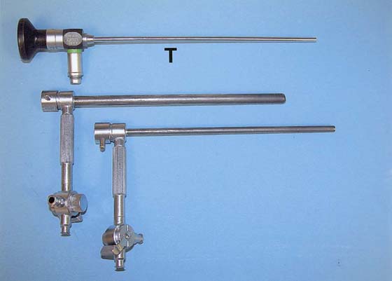
FIGURE 123–1 Components of the urethroscope. The 0° telescope (T) is shown at the top. Below are two sheaths (15F and 24F).
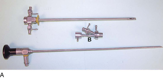
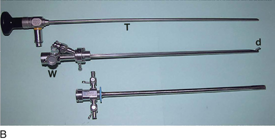
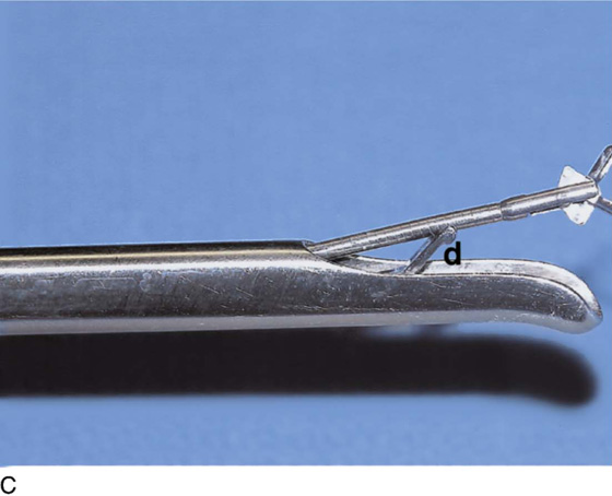
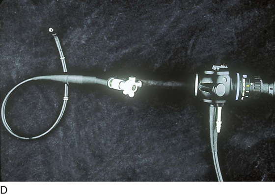
FIGURE 123–2 Components of a rigid cystoscope. A. Above is the sheath (17F) with water intake valves on the right and left. In the center is a bridge with an operating channel that attaches to the above sheath. Lowermost is a telescope, which can range from 30° to 70°. In this case, the telescope has a 70° lens. B. This rigid cystoscopic system consists of a telescope (T), an operative sheath with a bridge and terminal deflector (d), and an operative sheath without the deflector. The deflector (d) is controlled by the wheel (W) device mounted onto the proximal portion of the sheath. C. Close-up of the deflector (d). Note how the deflector permits manipulation of the biopsy forceps. D. Unlike the rigid cystoscope, the flexible device combines optical, irrigation, and operating channels in a single unit.
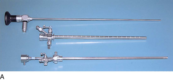
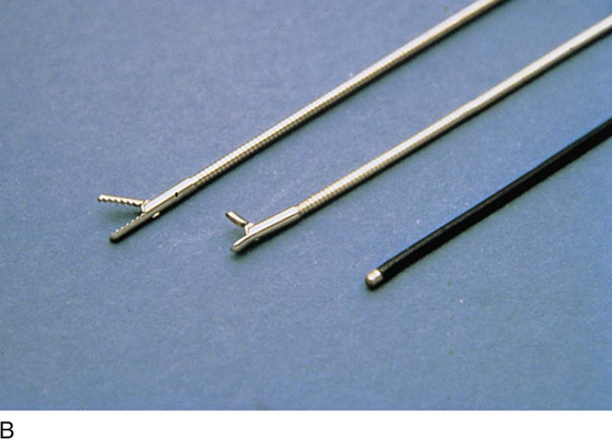
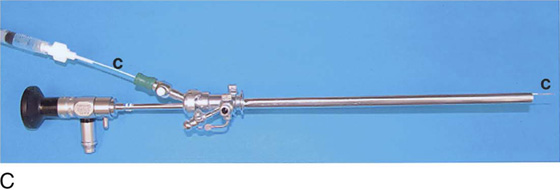
FIGURE 123–3 Components of operative hysteroscopic sheaths. A. The telescope is usually 0° or 30°. In this case, the telescope has a 12° lens. B. Accessory instruments that are passed via the channel and into the bladder include (from left to right) alligator grasping forceps, biopsy forceps, and a coagulating electrode. C. An injection needle has been placed through the channel, and a collagen implant (Contigen) (c) will be injected. (B from Cundiff GW, Bent AE: In Endoscopic Diagnosis of the Female Lower Urinary Tract. WB Saunders, UK London, 1999, with permission.)
Indications and Techniques
Indications for visualizing the anatomy of the female urethra and bladder include recurrent urinary tract infection, irritative bladder and urethral symptoms, hematuria, urogenital fistula, urethral or bladder diverticulum, complicated urinary stress incontinence, unresolved overactive bladder, suspected interstitial cystitis, calculus, suspected bladder or urethral cancer, obstructive voiding symptoms, suspected foreign body, assessment of ureteral function, and staging for cervical cancer. The procedure is performed in the office or ambulatory clinic. The patient is examined in the lithotomy position, and generally no analgesia is used. Topical anesthesia may be applied but usually is needed only on the cystoscopic sheath to allow it to slide along the tissues. The urethra is visualized using a 0° telescope with the infusion fluid (sterile water or saline) running briskly, by passing the instrument through the distal urethra and advancing it slowly to the bladder neck. The bladder is visualized by passing the 30° or 70° telescope with attached bridge and 17F sheath through the urethra in a smooth motion in a direction toward the umbilicus. The bladder is systematically examined at each hour of an imaginary clock, and then the trigone and ureters are visualized carefully (Fig. 123–4).
Urethroscopy (Normal and Abnormal Findings)
The urethral mucosa is visualized as the instrument is passed through the urethra toward the bladder neck (Figs. 123–5 through 123–7). The effects of hold, cough, and strain maneuvers are observed at the bladder neck. The urethrovesical junction normally closes (Fig. 123–8). Voiding or urethral opening secondary to detrusor activity causes the urethra to open widely (Fig. 123–9). A similar picture is noted if the bladder neck is visualized in a patient with detrusor instability (Fig. 123–10). With the bladder relatively full and a finger compression beyond the end of the scope, the scope is slowly withdrawn as the infusing fluid distends the urethra. Periurethral glands (Fig. 123–11A through C) and exudate from the glands may be observed (Fig. 123–12). Other benign findings include inclusion cysts (Fig. 123–13A, B) and fronds and polyps (Fig. 123–14A through C).
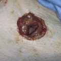
Pathologic changes include urethral prolapse (Fig. 123–15A, B), caruncle (Fig. 123–16), inflammation (Fig. 123–17A through C), diverticulum (Fig. 123–18A through C), fistula (Fig. 123–19), and an ectopic ureter opening at the bladder neck (Fig. 123–20).
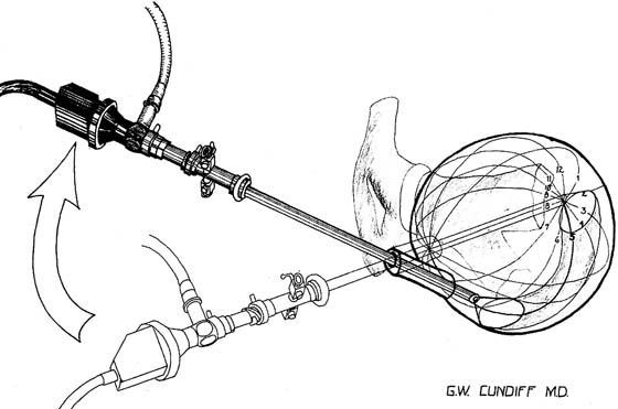
FIGURE 123–4 Cystoscopic evaluation of the bladder. The bladder cavity is evaluated by making 12 sweeps along each hour of the clock from the bladder dome to the urethrovesical junction. The 5 o’clock examination is being performed, so the light cord is at 11 o’clock, or 180° opposite the direction the lens is looking. (From Cundiff GW, Bent AE: In Endoscopic Diagnosis of the Female Lower Urinary Tract. WB Saunders, UK London, 1999, with permission.)
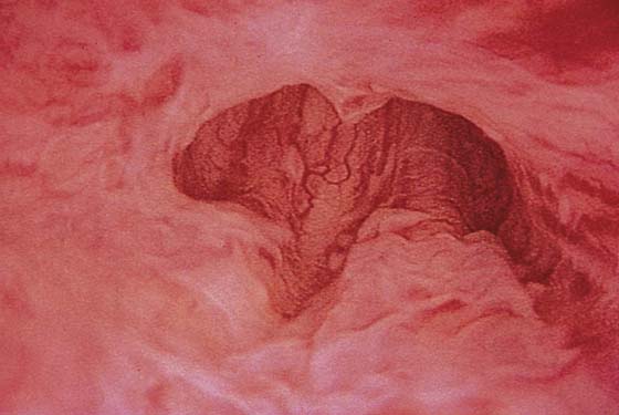
FIGURE 123–5 Normal urethra. (From Cundiff GW, Bent AE: In Endoscopic Diagnosis of the Female Lower Urinary Tract. WB Saunders, UK London, 1999, with permission.)
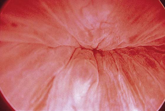
FIGURE 123–6 Coaptation of urethra. (From Cundiff GW, Bent AE: In Endoscopic Diagnosis of the Female Lower Urinary Tract. WB Saunders, UK London, 1999, with permission.)
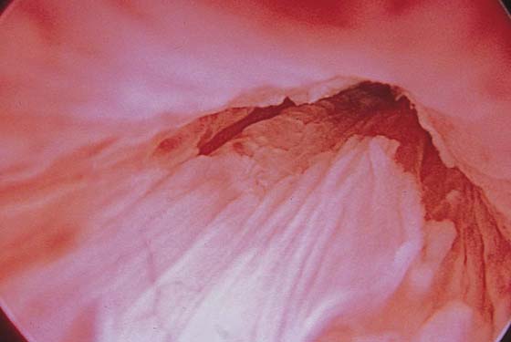
FIGURE 123–7 Urethral metaplasia. (From Cundiff GW, Bent AE: Endoscopic Diagnosis of the Female Lower Urinary Tract. WB Saunders, UK London, 1999, with permission.)
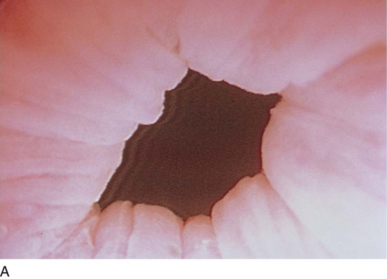
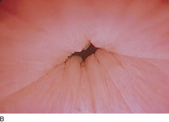
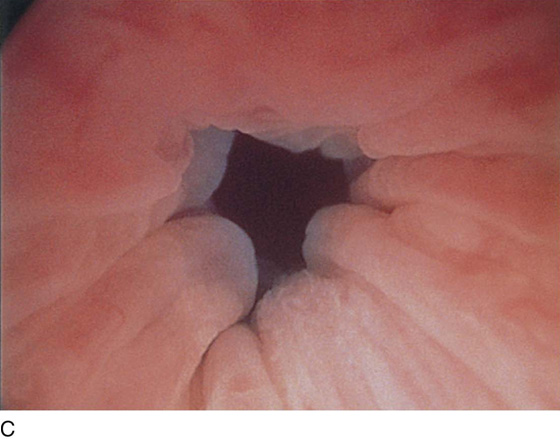
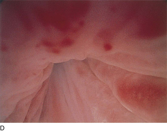
FIGURE 123–8 Maneuvers at the bladder neck. A. Open urethrovesical junction. B. Closed urethrovesical junction. C. Open urethrovesical junction. D. Closed urethrovesical junction. (From Cundiff GW, Bent AE: In Endoscopic Diagnosis of the Female Lower Urinary Tract. WB Saunders, UK London, 1999, with permission.)
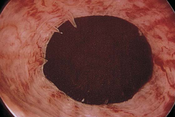
FIGURE 123–9 Urethra during voiding. (From Cundiff GW, Bent AE: In Endoscopic Diagnosis of the Female Lower Urinary Tract. WB Saunders, UK London, 1999, with permission.)
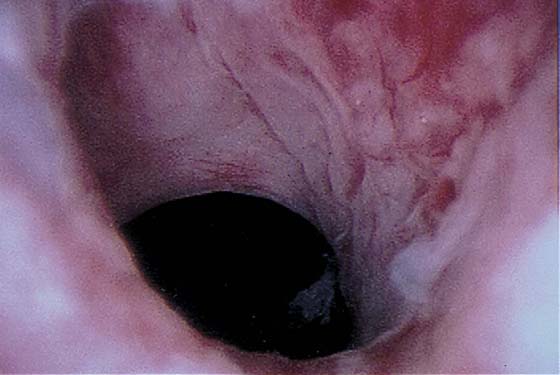
FIGURE 123–10 Urethra in a patient with detrusor instability.
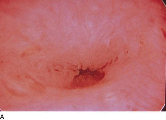
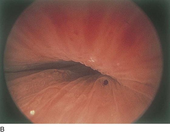
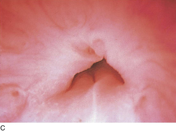
FIGURE 123–11 A. Periurethral gland openings, with several opening circumferentially. B. Large openings at 3 o’clock. C. Openings at 12, 4, and 8 o’clock.
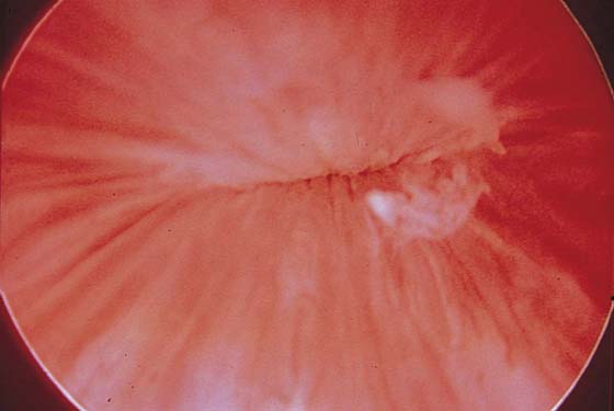
FIGURE 123–12 Exudate from periurethral glands. (From Cundiff GW, Bent AE: In Endoscopic Diagnosis of the Female Lower Urinary Tract. WB Saunders, UK London, 1999, with permission.)
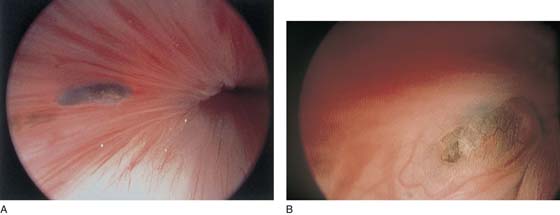
FIGURE 123–13 A. Urethral inclusion cysts. B. Urethral inclusion cyst at 7 o’clock.
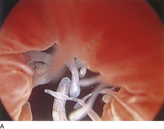
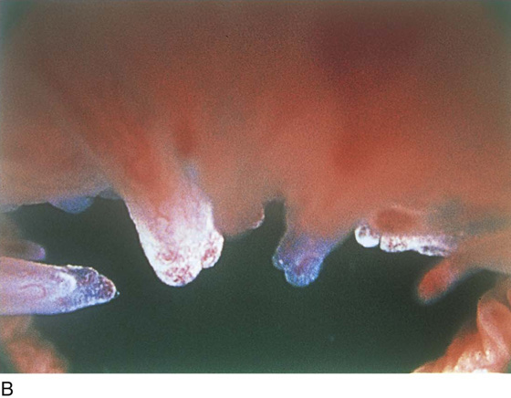
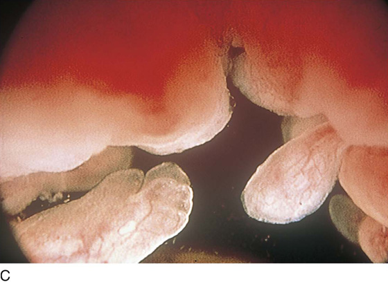
FIGURE 123–14 A. Fronds and polyps of urethra. B. Polyps at urethrovesical junction. C. Magnified view of urethral polyps.
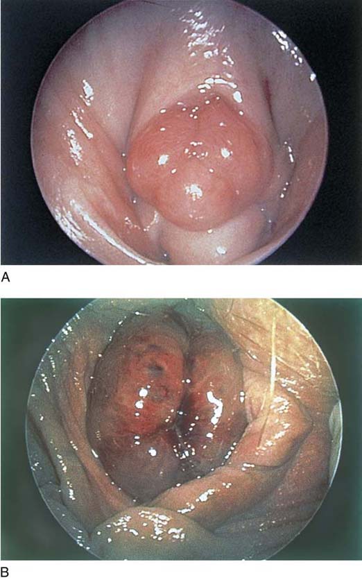
FIGURE 123–15 A. Urethral prolapse. B. Urethral prolapse.
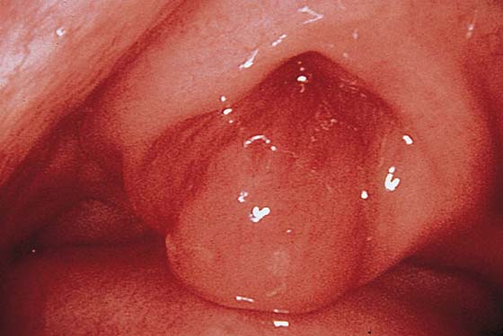
FIGURE 123–16 Urethral caruncle. (From Cundiff GW, Bent AE: In Endoscopic Diagnosis of the Female Lower Urinary Tract. WB Saunders, UK London, 1999, with permission.)
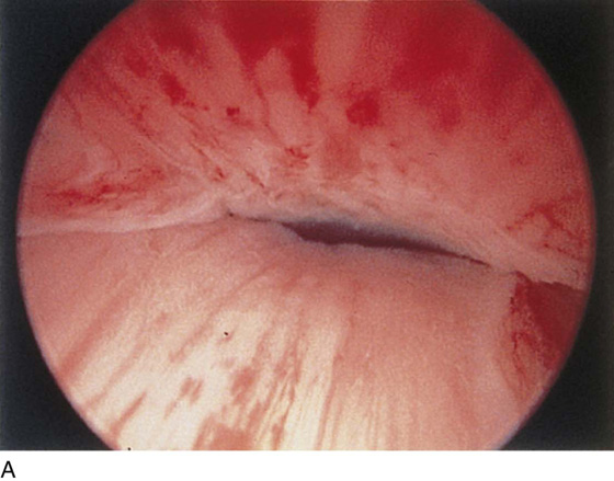
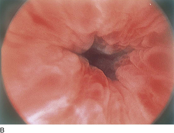
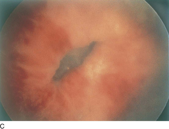
FIGURE 123–17 A. Urethral inflammation. B. Urethral inflammation. C. Severe urethral inflammation.
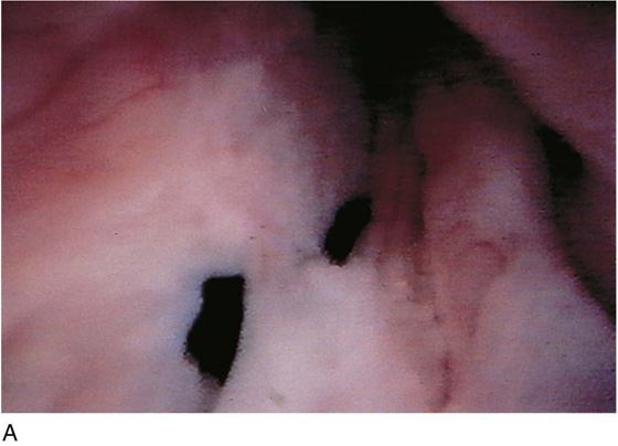
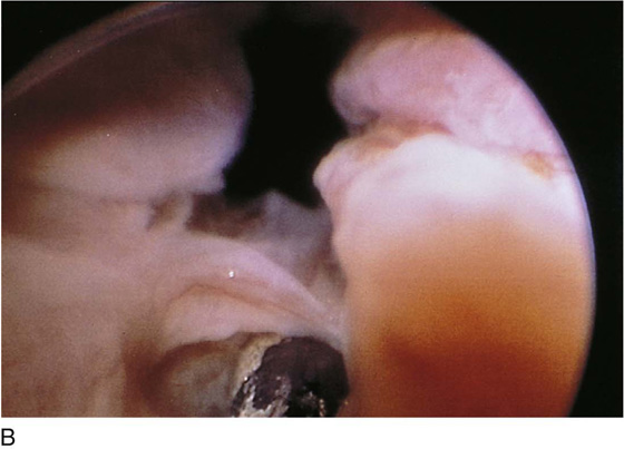
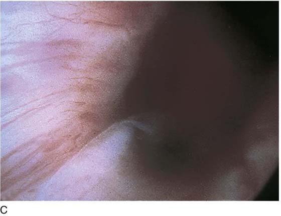
FIGURE 123–18 Urethral diverticulum. A. Chandelier diverticular openings. B. Urethral lumen at top with sound in diverticulum at 6 o’clock. (From Cundiff GW, Bent AE: In Endoscopic Diagnosis of the Female Lower Urinary Tract. WB Saunders, UK London, 1999, with permission.) C. Large midurethral diverticulum.
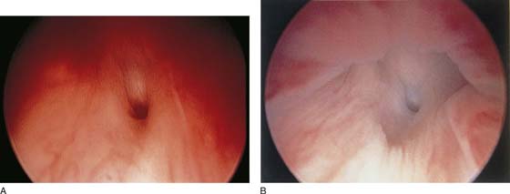
FIGURE 123–19 A and B. Urethrovaginal fistula.
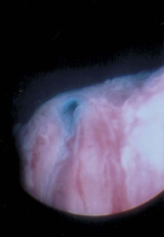
FIGURE 123–20 Ectopic ureter. Ureteral orifice opening at the urethrovesical junction.
Cystoscopy (Normal and Abnormal Findings)
The field of view is 180° opposite the light cord. A vaginally placed finger is occasionally needed to visualize the structures at the base of the bladder, especially in cases of marked prolapse with cystocele. The bladder should easily hold from 350 to 500 mL of fluid. The air bubble at 12 o’clock (Fig. 123–21) is observed first, then the clock faces from 1 to 5, then 11 back to 7. Finally, the trigone and ureteral opening are observed (Fig. 123–22A through D). The function of the ureters may be observed, especially if the patient has ingested some phenazopyridine (Pyridium) (Fig. 123–23). These other benign findings may be observed: uterus indenting the bladder (Fig. 123–24), paravaginal defect (Fig. 123–25), double ureters (Fig. 123–26), ureterocele (Fig. 123–27), cystitis cystica (Fig. 123–28A through C), bladder wall cysts (Fig. 123–29), bladder pigmentation (Fig. 123–30), prominent bladder venous channels (Fig. 123–31), bladder trabeculation (Fig. 123–32), and old scars (Fig. 123–33A through C). Pathologic changes that can be seen include trigonitis (Fig. 123–34), inflammation (Fig. 123–35A through E), cystitis glandularis (Fig. 123–36), interstitial cystitis (Fig. 123–37), foreign body (Fig. 123–38A through F), fistula (Fig. 123–39), and cancer (Fig. 123–40A through D).
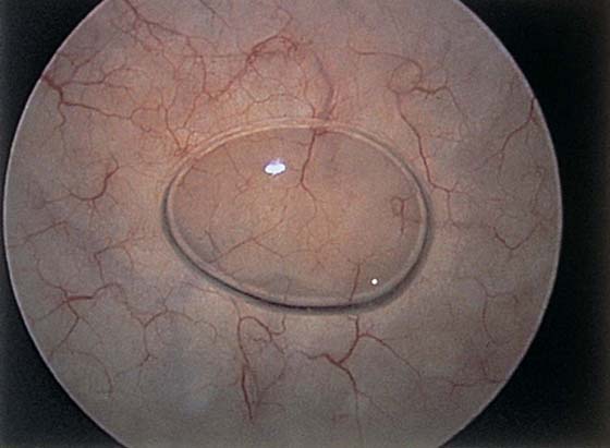
FIGURE 123–21 Air bubble at the dome of bladder.
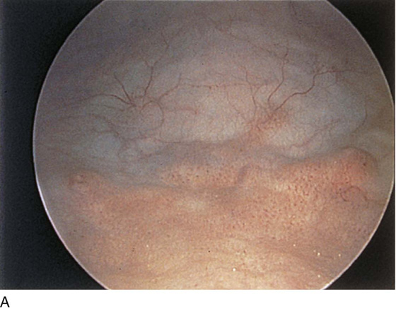
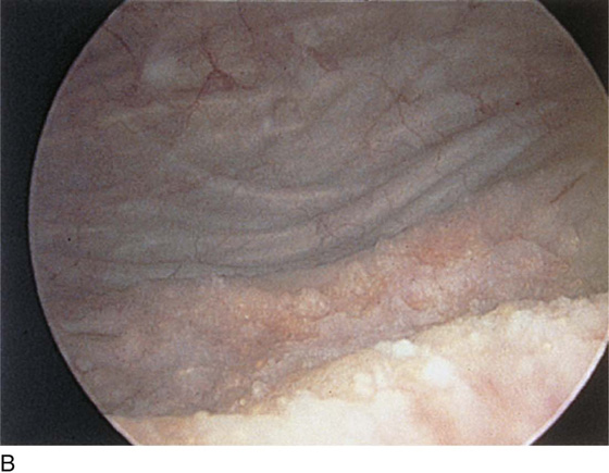
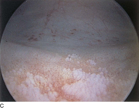
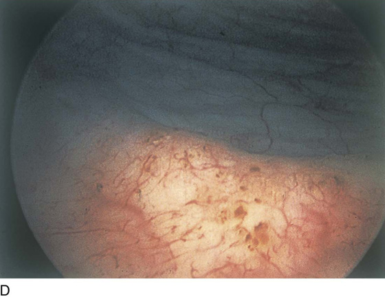
FIGURE 123–22 Trigone and ureters. A. Normal trigone. B. Granular trigone with the ureters at the lateral margins. C. Granular trigone. D. Pigmentation in the trigonal area.
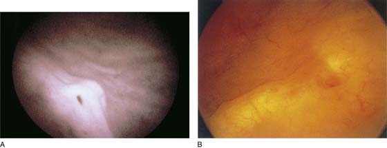
FIGURE 123–23 Ureteral function. A. Right ureter. B. Left ureter with Pyridium staining. (From Cundiff GW, Bent AE: In Endoscopic Diagnosis of the Female Lower Urinary Tract. WB Saunders, UK London, 1999, with permission.)
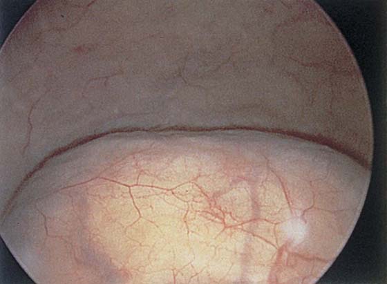
FIGURE 123–24 Uterus pressing into the inferior posterior wall of the bladder.
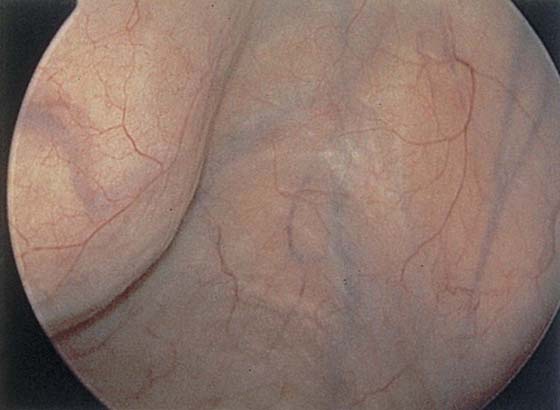
FIGURE 123–25 Right paravaginal defect.
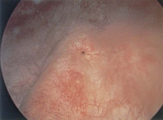
FIGURE 123–26 Double ureters.
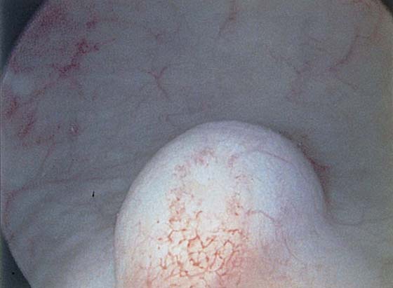
FIGURE 123–27 Ureterocele.
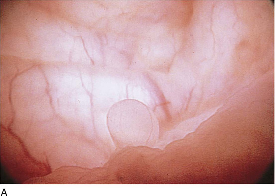
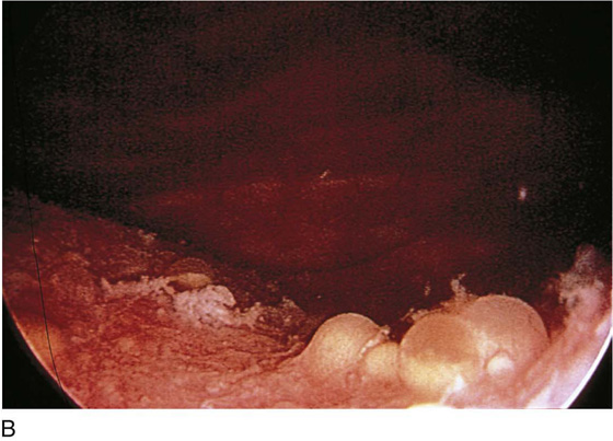
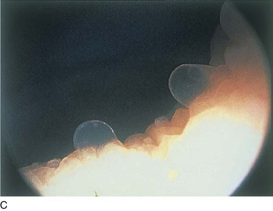
FIGURE 123–28 Cystitis cystica. A. Single cyst at the trigone. B. Yellow and clear cysts at the trigone. (From Cundiff GW, Bent AE: In Endoscopic Diagnosis of the Female Lower Urinary Tract. WB Saunders, UK London, 1999, with permission.) C. Clear cysts at the urethrovesical junction.
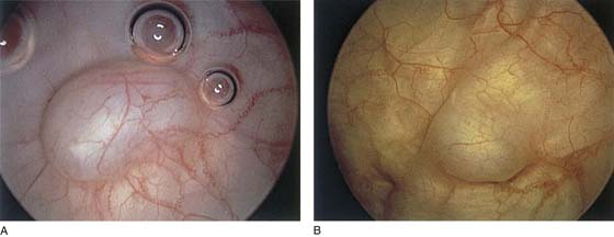
FIGURE 123–29 A and B. Bladder wall cysts.
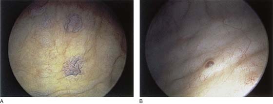
FIGURE 123–30 A and B. Bladder wall pigmentation.
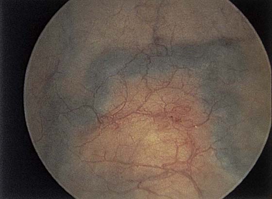
FIGURE 123–31 Bladder wall venous channel.
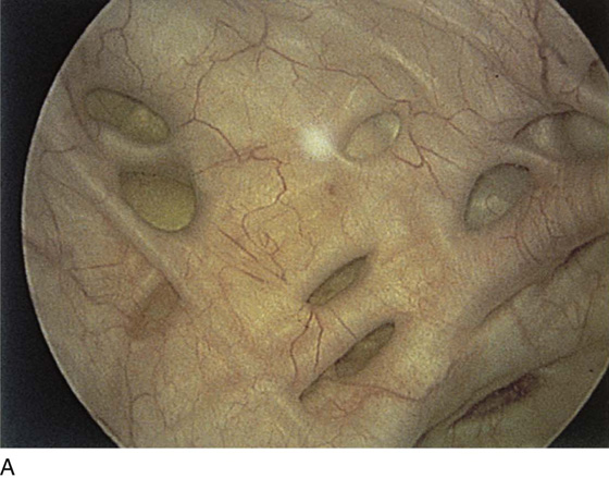
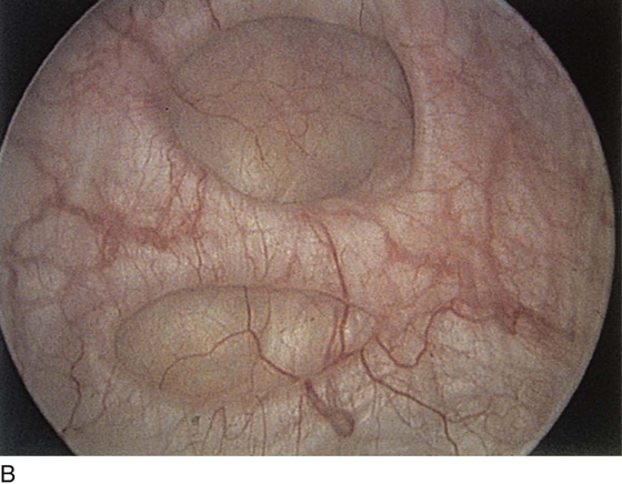
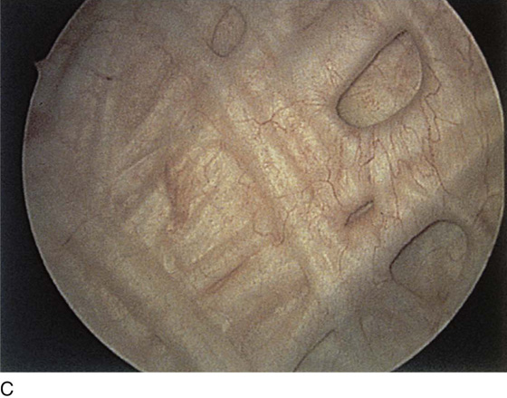
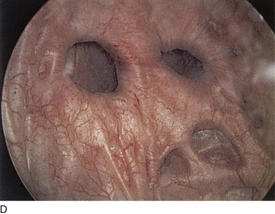
FIGURE 123–32 A through D. Trabeculation of bladder wall.
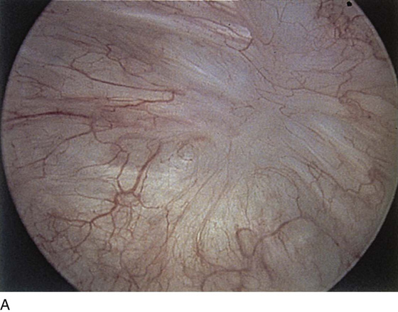
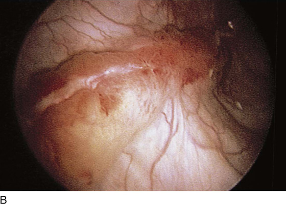
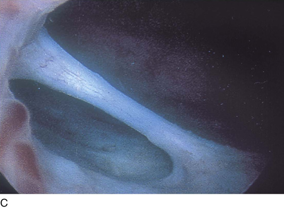
FIGURE 123–33 A and B. Bladder wall scars. C. Prominent synechia of the bladder.
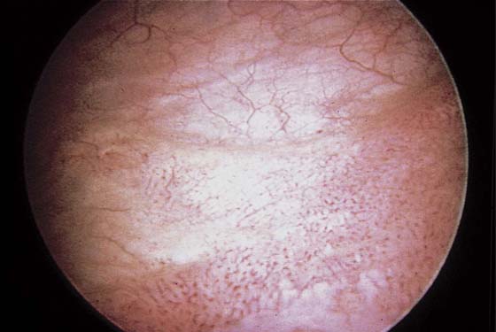
FIGURE 123–34 Trigonitis. (From Cundiff GW, Bent AE: In Endoscopic Diagnosis of the Female Lower Urinary Tract. WB Saunders, UK London, 1999, with permission.)
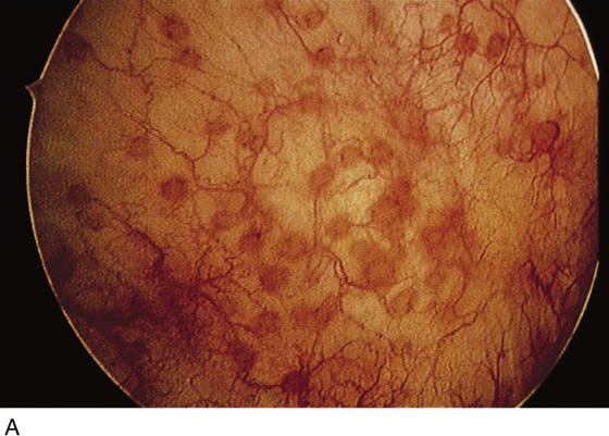
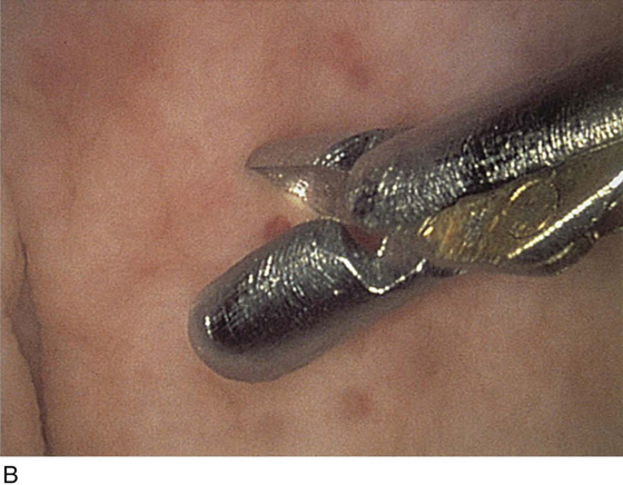
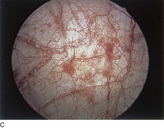
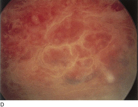
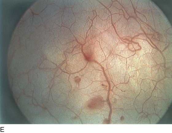
FIGURE 123–35 Inflammation. A. Inflammatory plaques. B. Biopsy of plaque. C. Inflammation with hemorrhagic spots. D. Marked hemorrhagic areas. E. Focal hemorrhage with inflammation.
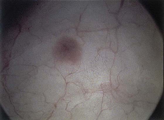
FIGURE 123–36 Cystitis glandularis.
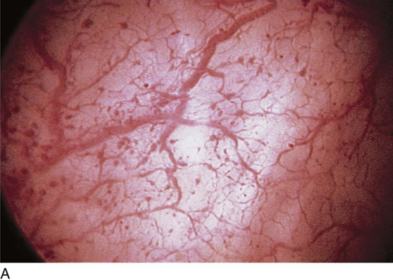
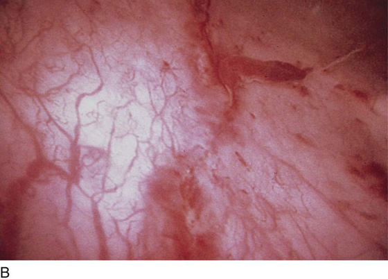
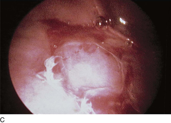
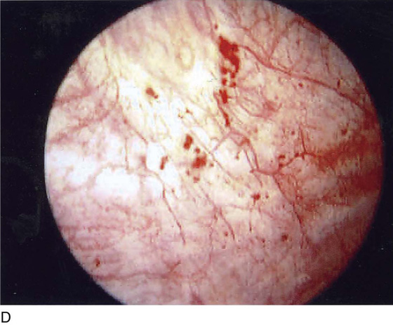
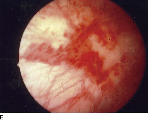
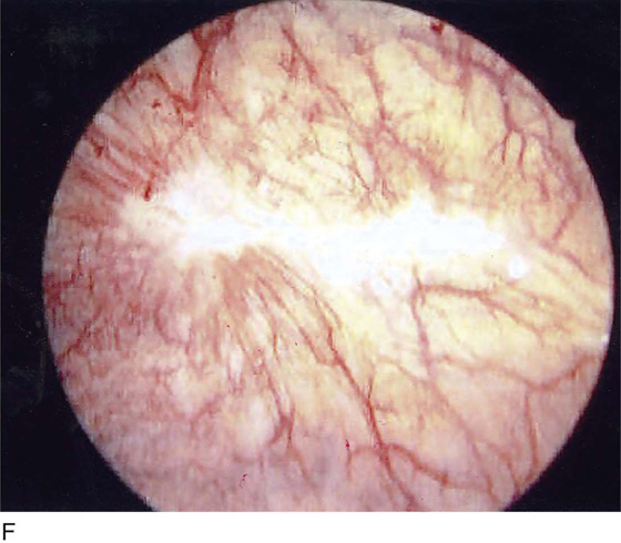
FIGURE 123–37 Interstitial cystitis. A. Petechiae and glomerulations. B. Hemorrhagic areas after bladder distention. C. Mucosal rupture after distention. (From Cundiff GW, Bent AE: In Endoscopic Diagnosis of the Female Lower Urinary Tract. WB Saunders, UK London, 1999, with permission.) D. Note the petechiae and glomerulation in the mucosa of the bladder. E. Linear hemorrhage. F. Interstitial cystitis showing Hunner’s ulcer (white scar in center of the figure).
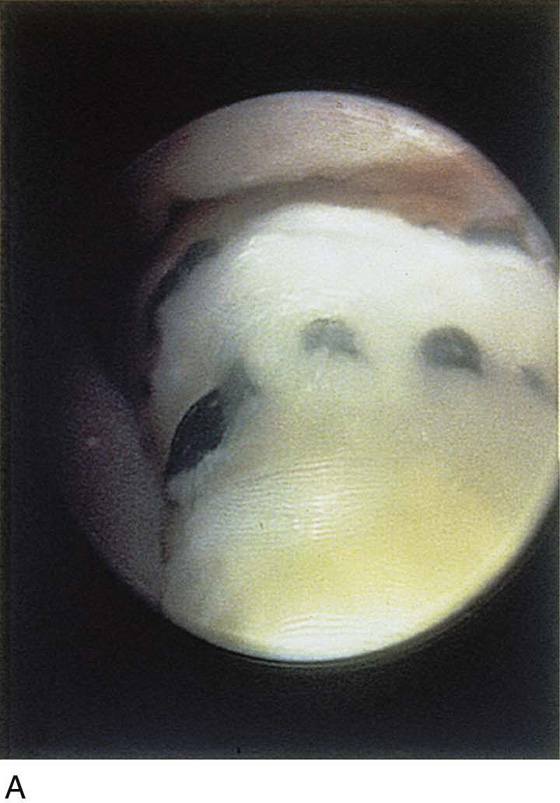
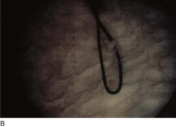
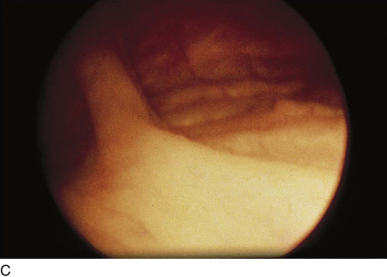
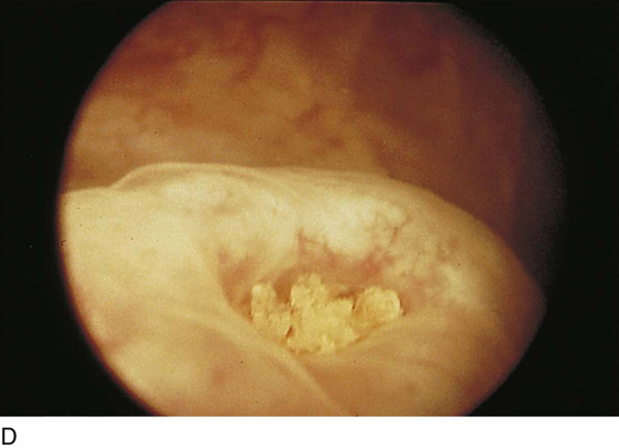
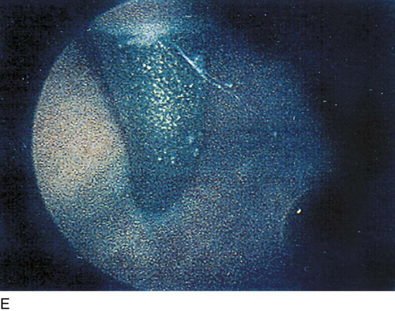
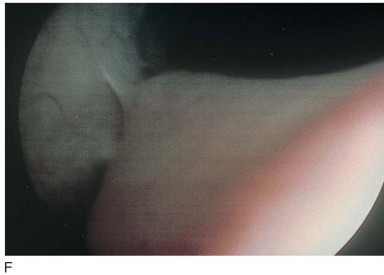
FIGURE 123–38 Foreign bodies. A. ProteGen sling in urethra. B. Suture through the bladder wall. C. Fascia lata sling. D. Ureteral stones. E. TVT needle. (From Cundiff GW, Bent AE: In Endoscopic Diagnosis of the Female Lower Urinary Tract. WB Saunders, UK London, 1999, with permission.) F. Epithelialized suture.
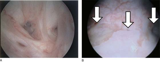
FIGURE 123–39 Vesicovaginal fistula. A. Bladder side. B. Vesicovaginal fistula arising from the midportion of the trigone (center arrow); right and left arrows denote ureteral orifices.
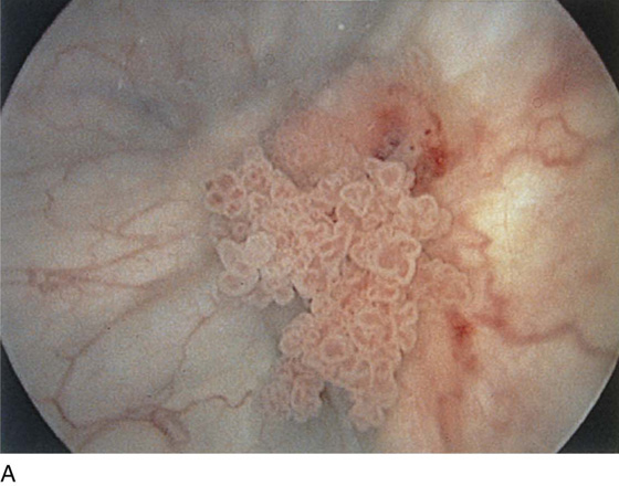
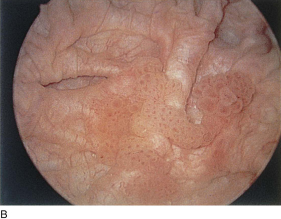
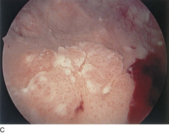
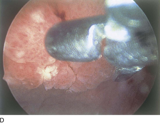
FIGURE 123–40 A through C. Bladder cancers. D. Directed biopsy of bladder cancer.
Operative Cystoscopy
Bladder Biopsy
Biopsy of the bladder is carried out in the office or outpatient setting. The bladder wall may be anesthetized by placing 50 mL of 4% lidocaine solution in the bladder for 5 minutes. The second aid is to place a bladder pillar block using 5 mL of 1% lidocaine injected 3 mm submucosally at the bladder pillars (Fig. 123–41). Bladder biopsy may require a 22F sheath to accommodate a biopsy instrument. The instrument is advanced until seen in the field of view. Gross movements are made by moving the scope, and finer ones are made by moving the biopsy instrument.
Ureteral Catheterization
Ureteral patency is assessed in the operating room by injecting indigo carmine dye (2.5 to 5.0 mL) intravenously and then observing the dye-stained urine exiting from the ureters after 5 or more minutes (Fig. 123–42). Jets of urine are seen at the time of regular cystoscopy, indicating functioning ureters. At the time of surgery, it is imperative that the surgeon be certain that the ureters and bladder are intact. Failure to see dye on either side requires catheterization of that ureter and appropriate management to relieve the blockage. Ureteral catheterization is usually performed with the catheter threaded through the operating channel of the cystoscope, with an Albarran bridge in place. Once the ureteral orifice is visualized, the catheter (Fig. 123–43) is advanced into view, and then by rotation of the scope, the catheter is oriented in the axis of the ureteral lumen. The scope is advanced to gently start the catheter into the ureter, and then the catheter is manually advanced to the desired location (Fig. 123–44A, B).
Injection of Bulk-Enhancing Agents
Collagen injection therapy is an outpatient or office procedure. Equipment includes a nonbeveled sheath (size 20F to 21F), with a 12° to 25° lens. The injection is most readily performed by the transurethral route. The collagen injection needle is placed in the assembled cystoscope with the needle lumen filled with 0.4 mL of 1% lidocaine. The needle is inserted approximately 2 cm from the bladder neck at 3 o’clock and is advanced 1 cm (Fig. 123–45). The injection is then performed, depositing the material 1 cm distal to the bladder neck. The needle is flushed with lidocaine and then is removed from the urethral wall. A second injection of 2.5 mL of collagen is performed at 9 o’clock. Usually 5 to 7.5 mL of collagen provides excellent coaptation of the urethrovesical junction (Fig. 123–46). A specially designed endoscopic system facilitates transurethral injection of bulk-enhancing agents. Periurethral collagen injection may also be performed. The periurethral area is anesthetized by injecting 1% lidocaine with indigo carmine along the lateral side of the urethra. The short 22-gauge collagen injection needle is then advanced through the periurethral tissues until it rests just distal to the bladder neck, and as the lidocaine/indigo carmine mixture is injected, the bulging and blue color are visible under the urethral mucosa (Fig. 123–47A through G). The rest of the injection is similar to the technique for transurethral injection in that the bladder neck is observed during the injection, and it closes gradually as the collagen material accumulates just distal to the bladder neck. Follow-up endoscopy usually shows evidence of old collagen.
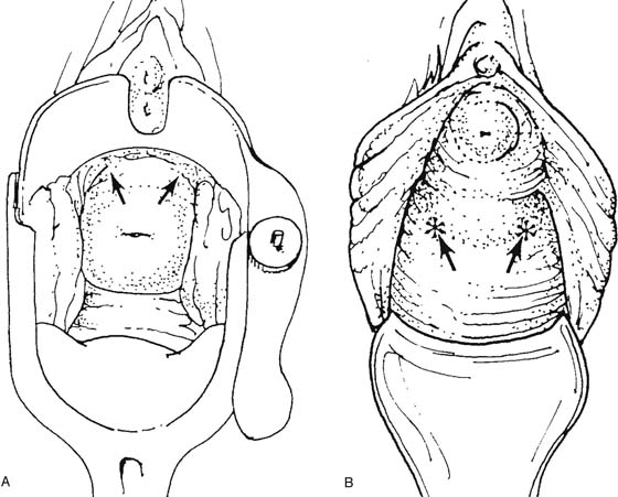
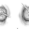
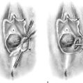
FIGURE 123–41 Bladder pillar block. A. Injection at 2 and 10 o’clock with the cervix in situ. B. Injection at approximately 4 and 8 o’clock in the absence of the cervix. (From Ostergard DR: Bladder pillar block anesthesia for urethral dilatation in women. Am J Obstet Gynecol 1980;136:187–188, with permission.)
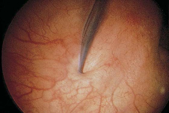
FIGURE 123–42 Ureteral patency. Indigo carmine–stained urine spurting from the ureter. (From Cundiff GW, Bent AE: In Endoscopic Diagnosis of the Female Lower Urinary Tract. WB Saunders, UK London, 1999, with permission.)
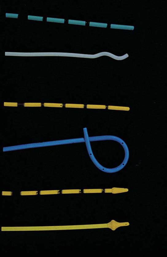
FIGURE 123–43 Ureteral catheters. From top to bottom: general purpose, whistle tip, filiform, double J, acorn, and Rutner catheters. (From Cundiff GW, Bent AE: In Endoscopic Diagnosis of the Female Lower Urinary Tract. WB Saunders, UK London, 1999, with permission.)
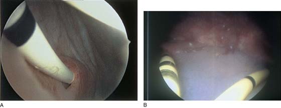
FIGURE 123–44 A. Ureteral catheter in situ. B. Bilateral ureteral catheters in situ.
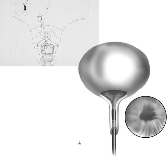
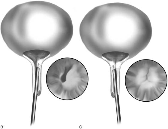
FIGURE 123–45 A. The needle is positioned at the urethrovesical junction. (From Cundiff GW, Bent AE: In Endoscopic Diagnosis of the Female Lower Urinary Tract. WB Saunders, UK London, 1999, with permission.) B. The needle penetrates the mucosa on the left, and the collagen is injected. C. The needle penetrates the mucosa on the right, and the collagen is injected. The inset shows the ballooned urethral wall coapting.
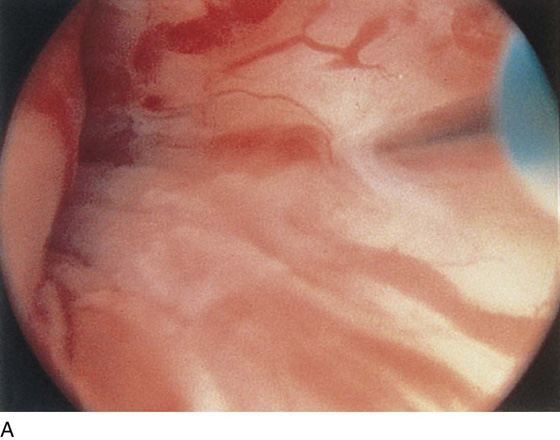
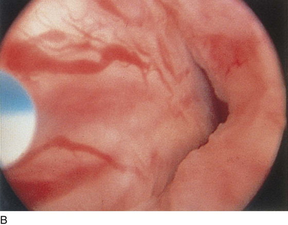
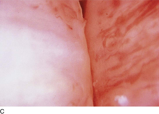
FIGURE 123–46 Transurethral collagen injection. A. 3 o’clock position. B. 9 o’clock position. C. Occluded bladder neck. (From Cundiff GW, Bent AE: In Endoscopic Diagnosis of the Female Lower Urinary Tract. WB Saunders, UK London, 1999, with permission.)
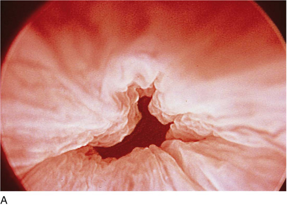
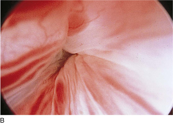
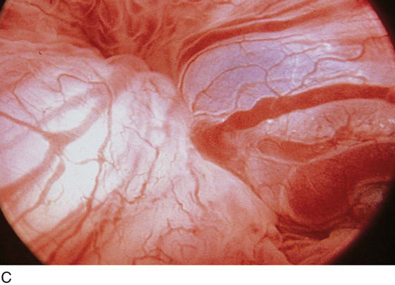
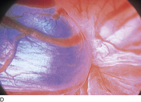
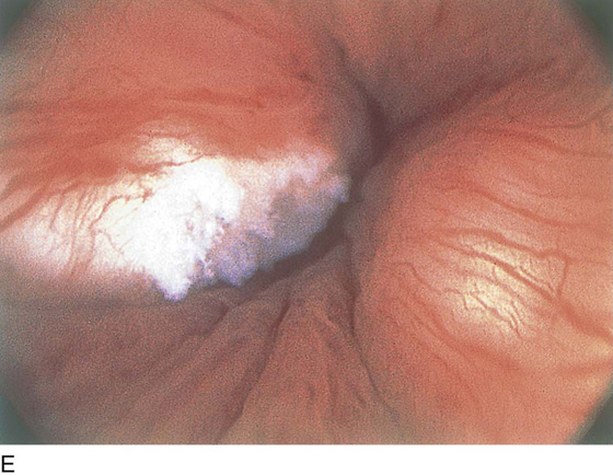
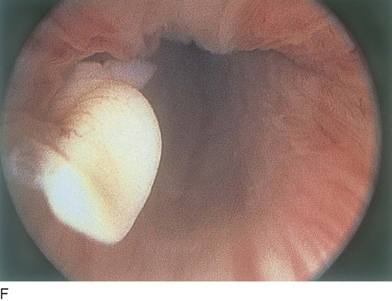
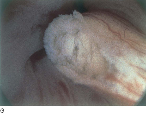
FIGURE 123–47 Periurethral collagen injection. The scope is a 0° urethroscope that is positioned distal to the bladder neck. A. Open urethrovesical junction. B. Left side being injected. C. Right periurethral injection. D. The injection is completed and the bladder neck is closed. E through G. Old collagen.
Suprapubic Telescopy
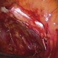
Suprapubic telescopy is an alternative to transurethral cystoscopy for evaluating the lower urinary tract during open abdominal pelvic surgery. Telescopy is an extraperitoneal technique that begins with closure of the anterior peritoneum to prevent contamination of the peritoneal cavity with spilled urine. Five cubic centimeters of intravenous indigo carmine is given to help identify the ureteral orifices. The bladder is filled in a retrograde fashion through a triple-lumen transurethral Foley catheter to at least 400 mL. A purse string suture is placed through the extraperitoneal dome of the bladder with a 3-0 absorbable suture. The suture should be placed through the muscularis layer of the bladder wall. A stab incision is made with a knife in the middle of the purse string; this is followed by immediate insertion of a 30° telescope through the stab wound. Drawing up of the purse string sutures prevents leakage without limiting movement of the telescope (Fig. 123–48). Because distention of the bladder is achieved through the transurethral catheter, the sheath and bridge are unnecessary, and the telescope is inserted alone. A 30° telescope provides the best view of the trigone and ureteral orifices while also permitting a thorough bladder survey. Orientation can be achieved by identifying the transurethral Foley catheter bulb and locating the trigone beneath the bulb (Fig. 123–49). If suprapubic catheterization is planned, the catheter can be placed through the same stab incision when telescopy is completed (Fig. 123–50).
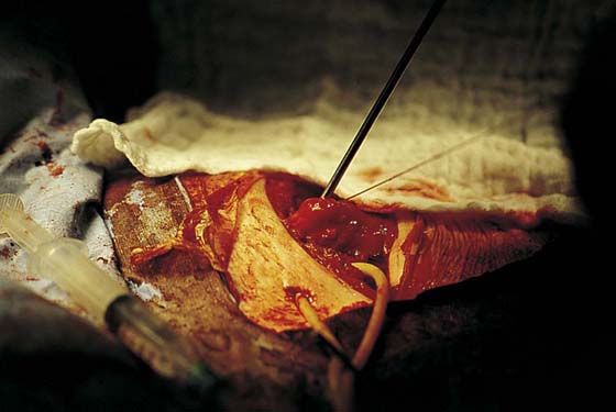
FIGURE 123–48 Technique of suprapubic telescopy. Note that drawing up on the purse string prevents leakage during telescopy.
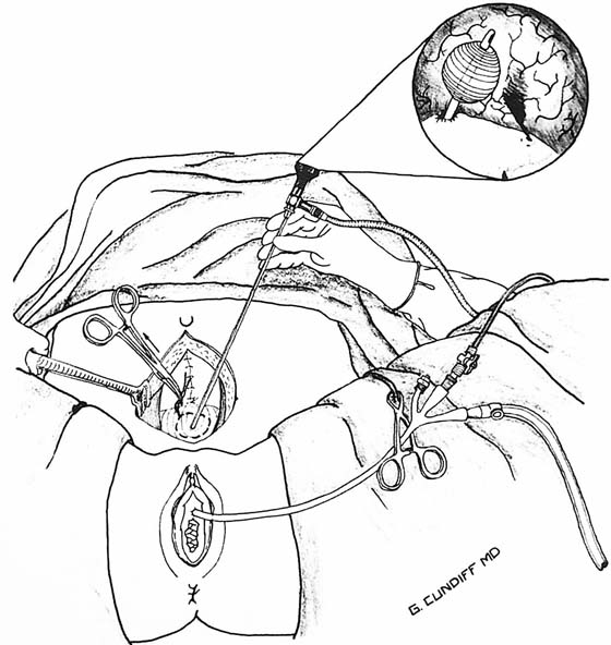
FIGURE 123–49 Suprapubic telescopy. The bladder is filled retrogradely through a transurethral triple-lumen Foley catheter to a volume of 400 mL. A purse string absorbable suture is placed into the muscularis layer of the dome of the bladder, and a stab incision is made within the purse string for insertion of the telescope. The purse string is tightened sufficiently to prevent leakage without limiting movement of the telescope. Orientation can be achieved by identifying the transurethral Foley catheter bulb. The trigone is beneath the bulb with the urethral and ureteral orifices at its apices. (From Cundiff GW, Bent AE: In Endoscopic Diagnosis of the Female Lower Urinary Tract. WB Saunders, UK London, 1999, with permission.)
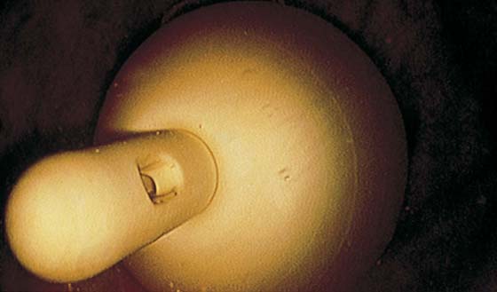
FIGURE 123–50 The Foley catheter as viewed with a suprapubic cystoscope.