80 Conduction Disturbances and Cardiac Pacemakers
 Conduction Disturbances
Normal Cardiac Conduction
The impulse is generated by a specialized group of cells with the ability to depolarize spontaneously. Initial depolarization of the SA node is not seen on the electrocardiogram (ECG). The P wave is generated when the impulse spreads throughout the atria. There is no specific conduction system in the atria to convey the SA node impulse to the AV node.1 The impulse is transmitted by depolarization of adjacent atrial myofibrils. Approximately halfway through the P wave, the impulse reaches the AV node. The second half of the P wave is due to left atrial depolarization.
Failure of Impulse Conduction
Failure of conduction can occur anywhere along the conduction pathway. AV node block is most often caused by medications, increased parasympathetic tone, or ischemia. AV node blocks are usually reversible, except when infarction permanently damages a portion of the conduction pathway. Infranodal blocks are rarely caused by physiologic abnormalities. Structural heart disease and anatomic disruption of the conduction system are the main causes of infranodal heart block. Rare causes of infranodal block include disruption of the bundle of His from aortic valve calcification, Lenègre’s disease (idiopathic degeneration of Purkinje fibers), and Chagas’ disease.2
Clinical Presentation
Syncope and presyncope are the most dramatic symptoms of conduction disturbances; palpitations, dyspnea, angina, and fatigue are seen as well. Many patients are asymptomatic. A significant number of patients develop bradydysrhythmias after an acute myocardial infarction (AMI) (Table 80-1).3
TABLE 80-1 Incidence of Bradydysrhythmias in Acute Myocardial Infarction
| Rhythm | Incidence (%) |
|---|---|
| Any bradydysrhythmia | 25-30 |
| Sinus bradycardia | 25 |
| Junctional escape rhythm | 20 |
| Idioventricular escape rhythm | 15 |
| First-degree atrioventricular (AV) node block | 15 |
| Second-degree AV block type I | 12 |
| Second-degree AV block type II | 4 |
| Third-degree block | 15 |
| Right bundle branch block | 7 |
| Left bundle branch block | 5 |
| Left anterior fascicular block | 8 |
| Left posterior fascicular block | 0.5 |
Diagnostic Evaluation
A high-quality ECG is paramount for the appropriate evaluation of P waves and various intervals. Routine monitoring in the ICU is usually accomplished with a single or three-lead display at the bedside. The lead chosen should clearly delineate the P waves and QRS complexes. Complex arrhythmias may require Lewis leads, intraatrial leads, or esophageal ECG monitoring. Calipers significantly aid in the diagnosis of AV blocks and are helpful to “march out” P waves and intervals. Holter or continuous loop monitoring can also be an important tool in the evaluation of AV block.4 These monitors allow one to evaluate the cardiac conduction system during a patient’s activities of daily living. A monitoring period of at least 24 hours is recommended so that both daytime and nighttime activities are included.
Sinus Node Abnormalities
Sinus Arrest
Sinus arrest occurs when the pacemaker cells in the SA node fail to depolarize. Pauses of less than 3 seconds may be seen in up to 11% of normal individuals and should not cause concern.5 There is a higher incidence of sinus pause in athletes. Pauses longer than 3 seconds are usually considered pathologic and should be evaluated.
SA exit block and sinus arrest appear similar on ECGs, but they should be distinguished if possible. The duration of the pause in exit block is a multiple of the P-P interval. High-grade exit block cannot be distinguished from sinus arrest. The treatment is the same for both conditions.6
Carotid Sinus Hypersensitivity
Carotid sinus hypersensitivity is diagnosed when ventricular asystole greater than 3 seconds’ duration (usually due to a sinus pause or arrest) or a drop in systolic blood pressure greater than 50 mm Hg occurs in response to carotid massage. If symptoms occur, a 30 mm Hg drop in systolic blood pressure defines a positive response. Treatment is permanent pacing in symptomatic patients only.7
Postsurgical Bradydysrhythmias
Bradyarrhythmias are common after cardiac surgery. Valve surgery and septal myectomy can cause significant damage to the conduction system. Prolonged ischemia during heart transplantation may also result in sinus node or conduction system damage. The decision to place a permanent pacer should not be made until 5 to 7 days postoperatively, however, because the bradyarrhythmia may be temporary. Medication administered during surgery or reversible ischemia is often implicated. Pacing is required in 3.2% to 8.5% of patients with valve surgery and approximately 10% of patients with transplants.8
Atrioventricular Node Dysfunction
There are many causes and several manifestations of AV node dysfunction. Box 80-1 lists the causes of AV node abnormalities.
Box 80-1
Causes of Atrioventricular Node Dysfunction
Adapted from Wolbrette DL, Naccarelli GV. Bradycardias: sinus nodal dysfunction and atrioventricular conduction disturbances. In: Topol EJ, editor. Textbook of Cardiovascular Medicine. Philadelphia: Lippincott-Raven; 1998, p. 1655.
First-Degree Atrioventricular Block
First-degree AV block is characterized by a prolonged PR interval greater than 0.20 second in adults and 0.18 second in children who are not taking medications that can prolong the PR interval (Figure 80-1). All the P waves are conducted to the ventricles, and the PR interval is typically fixed. Potential causes of first-degree AV block include delayed conduction through the atria from the SA node to the AV node, a delay in AV node conduction, or prolonged infranodal conduction.
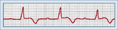
Conduction delays from the SA node to the AV node are typically due to structural causes such as right atrial enlargement or an ostium primum atrial septal defect. A delay in AV node impulse conduction is the most common cause of first-degree AV block. Patients with delayed conduction in the AV node often have a PR interval greater than 0.30 second. Infranodal causes of first-degree AV block are rare and are typically associated with a wide QRS complex due to disease in the fascicles or the bundle of His. First-degree AV block can also occur when each of these conduction times is at the upper limit of normal and summate to produce an overall prolongation of the PR interval.7
Second-Degree Atrioventricular Block Type I
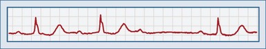
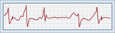
Second-degree AV block type I, or a Wenckebach (or Mobitz type I) rhythm, is defined by a progressive prolongation of the PR interval with each successive beat, with eventual failure of a P wave to conduct to the ventricles (Figure 80-2). This results in a dropped beat and failure of the ventricles to depolarize. The P waves occur at regular intervals. As the PR interval lengthens, the RR interval becomes shorter, which eventually results in decremental conduction. There is a reciprocal relationship between the RP interval and the PR interval.
Second-Degree Atrioventricular Block Type II
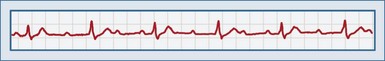
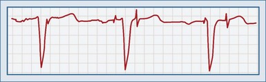
Second-degree AV block type II (or Mobitz type II block) is characterized by a sudden nonconducted P wave without a change in the PR interval. A P wave with no corresponding QRS complex is observed on the ECG (Figure 80-3). This is an inherently unstable rhythm, and serious pathology may be present. In contrast to the Mobitz type I rhythm, type II is described as a high degree of AV block, with P wave–to–QRS ratios of 3 : 1 and 4 : 1. A Mobitz type II rhythm is almost always due to an infranodal conduction disturbance. The conducted QRS complexes are often wide, and a bundle branch block pattern is often observed. Second-degree AV block can result from anterior wall MI. Type II second-degree AV block can progress to complete heart block.
Third-Degree Atrioventricular Block
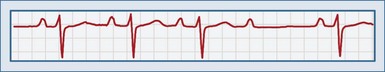
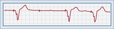
Third-degree AV block is characterized by complete AV dissociation. There is no conduction of the atrial signal through to the ventricle, so the atrial and ventricular systems operate independently. On ECGs, the P waves “march through” and are not associated with ventricular contraction. The PR intervals are irregular. The ventricular complexes may be junctional (narrow QRS complex; rate 40-60) or ventricular (wide QRS complex, rate <40). Depending on the escape heart rate, patients may present with tachypnea, dyspnea on exertion, fatigue, cyanosis, or syncope (Figure 80-4).
Third-degree block can be divided into congenital and acquired causes. Sixty percent of patients with congenital heart block are female. Patients with congenital third-degree block often have an escape rhythm with an adequate rate.9 Acquired third-degree block occurs most frequently in the seventh decade of life and usually requires permanent pacing; these patients are often male. Specific causes include medications, ischemia, progression from Mobitz type II rhythm, and infarction. Acute MI results in third-degree heart block in 14% of patients with inferior wall infarcts and 2% of patients with anterior infarcts. Third-degree block is usually observed within 24 hours after an MI. Third-degree block as a complication of inferior MI is usually temporary and may require only temporary pacing. Complete heart block as a result of anterior MI usually requires a permanent pacer.
 Pacemakers
The North American Society of Pacing and Electrophysiology and the British Pacing and Electrophysiology Group created a code consisting of five letters to describe pacemaker functions, known as the NBG pacemaker code (Table 80-2).10 The first three letters describe the antibradycardia functions, the fourth describes the programmability of rate responsiveness, and the fifth describes any antitachycardia functions. A pacemaker may carry one classification (e.g., DDD) but be capable of several modes of function, depending on how it is programmed. Indications for permanent pacing were updated by the American College of Cardiology in 2002.11
The pacemaker itself consists of two components: a pulse generator and wire leads connecting the generator to the heart. The pulse generator consists of a lithium-based battery and the circuitry to detect and analyze the cardiac rhythm and produce the output. The battery can last more than 10 years, depending on the type of programming; at the end of its life, it shows a gradual rate decrease, not an abrupt drop-off.12
Two types of lead systems exist: unipolar and bipolar. Bipolar leads are considered standard unless patient-specific factors warrant the use of a unipolar lead. Unipolar programming uses the lead in the endocardium as the cathode and the pacemaker unit itself as the anode. Because voltage in a unipolar lead is detected over a greater distance, the pacing spike is larger than with bipolar lead programming. Leads can be attached to the endocardium by active fixation (screwed into the myocardium) or passive fixation (held in place by fins). Passive fixation is associated with a greater incidence of dislodgment and perforation.13
Every pacer is programmed to fire after a maximum period in which no activity has been detected. This is called the lower rate-limiting interval, and it is the time between two consecutive paced beats. The escape interval is the time between a native complex and the following pacemaker spike. A slight delay beyond the lower rate-limiting interval can be programmed into the pacemaker when it senses a native QRS complex. This is an attempt to permit the heart to generate its own output and thus function in a more physiologic manner; this is called rate hysteresis, and it is found most often in ventricular demand pacemakers.14 Dual-chamber pacers have an interval programmed between atrial and ventricular spikes called the AV interval, which functions basically as the PR interval. The interval between a ventricular spike and the next atrial pacing spike is the ventriculoatrial interval. The AV and ventriculoatrial intervals sum to equal the lower rate-limiting interval.
Complications
Failure to Sense (Undersensing)
Undersensing occurs when the pacemaker generates output regardless of the patient’s underlying rhythm (Figure 80-5). A spike is seen at an interval earlier than the lower rate-limiting interval. Pacemaker output then competes with the patient’s own intrinsic rhythm. Although ventricular pacing can present a problem when the threshold for ventricular capture has been altered (e.g., by ischemia), and atrial pacing can produce atrial fibrillation, these are rarely urgent problems.15
Specific causes of failure to sense are listed in Table 80-3. Blanking is not a true cause; rather, it is an instance of functional undersensing in dual-chamber pacemakers. To prevent a pacemaker-induced tachycardia, a 12- to 125-millisecond period of inactivity is programmed into the ventricular component after an atrial complex. If an intrinsic QRS complex occurs during this period, it will not be sensed. Scar tissue does not conduct impulses as easily as normal myocardium does, so sensing may not occur. Most pulse generators begin asynchronous pacing at a critical point at the end of their life and will not sense intrinsic activity. Defibrillation can damage the unit; placing the defibrillator pad in an anteroposterior position may help. The unit should be observed closely after shocks are delivered.
| Cause | Treatment |
|---|---|
| Lead fracture | Replace lead |
| Lead dislodgment | Reposition lead or increase sensitivity |
| Insulation defect in pacing lead | Replace lead |
| Magnet interrogation | Remove magnet |
| Blanking | Decrease ventricular refractory period |
| Amplitude of P wave or QRS complex too low to be sensed | Increase sensitivity |
| Myocardial fibrosis | Increase sensitivity or reposition lead |
| Myocardial perforation | Increase sensitivity or reposition lead |
| End of battery life | Replace battery |
| Acute myocardial infarction | Treat myocardial infarction |
| Electrolyte disturbance | Correct electrolytes |
| Antidysrhythmic drugs | Increase sensitivity, change drug |
| Magnetic resonance imaging | Reprogram to VOO, AOO, or DOO mode |
| Defibrillation | Place defibrillator pads as far from pacemaker unit as possible, place in anteroposterior position |
| Complexes occurring in pacemaker’s refractory period | None, or use new generator with shorter refractory period |
Failure to Pace (Generate Output)
This complication is noted when a pacemaker spike is not seen after the lower rate-limiting interval has been exceeded (except when hysteresis has been programmed; Figure 80-6). Oversensing occurs when stimuli are erroneously sensed as pacemaker output. As a result, the expected proper output is inhibited; this can be continuous or intermittent. Failure to pace can be a devastating complication for a pacemaker-dependent patient. It is important to determine whether output is truly occurring or not. A 12-lead ECG should be done, because spikes may be too small to be seen in a specific lead. Several causes are possible (Table 80-4).
| Cause | Treatment |
|---|---|
| Lead fracture, loose connection, or insulation defect | Adjust or replace leads |
| Battery depletion | Replace battery |
| Pulse generator failure | Replace pulse generator |
| Cross-talk | Program a blanking period or safety pacing |
| Electromagnetic oversensing: | |
| Sensing P or T or U waves | Decrease sensitivity, or advance tip deeper into right ventricle |
| Myopotential sensing | Decrease sensitivity, or use bipolar sensing |
| Electrocautery | Decrease sensitivity, or electrically isolate patient |
| Extracorporeal shock wave lithotripsy | Decrease sensitivity, or use minimal equipment necessary |
| Transcutaneous electrical nerve stimulator (TENS) | Decrease sensitivity, stop TENS unit |
| Magnetic resonance imaging | Program to DOO, VOO, or AOO mode |
Failure to Capture
This complication occurs when a pacemaker fires as expected but fails to depolarize the myocardium. A pacer spike is seen on the ECG, but no QRS complex immediately follows it (Figure 80-7). This can be dangerous for a pacemaker-dependent patient and may require temporary pacing until the problem is fixed. Most cases are due to problems with the lead/tissue interface, although isolated problems in the leads or the myocardium can also occur (Table 80-5).13,16
| Cause | Treatment |
|---|---|
| Lead dislodgment from endocardial surface | Repair lead |
| Twiddler’s syndrome | Fix unit to chest wall |
| Lead fracture or break in insulation | Replace lead |
| Improperly or inadequately programmed voltage | Reprogram voltage |
| Battery failure | Replace battery |
| Cardiac perforation | Reposition lead (in operating room) or increase voltage |
| Increased threshold for capture: | |
| Fibrosis or scar tissue at contact site | Increase voltage or reposition lead |
| Myocardial ischemia | Treat ischemia |
| Metabolic: | Treat abnormality |
| Hyperkalemia | |
| Hypercarbia | |
| Hypoxemia | |
| Hypothyroidism | |
| Drugs: | Remove drug and replace with another |
| Beta-blockers | |
| Class Ia antidysrhythmics | |
| Verapamil | |
| Flecainide |
When a lead is placed into the myocardium, tissue fibrosis occurs over the first 4 to 6 weeks. Because scar tissue does not conduct as well as normal myocardium, the output voltage may need to be increased. Twiddler’s syndrome is seen when a patient fidgets with the generator and ends up pulling the leads from their attachments to the myocardium. It is confirmed by chest x-ray. The pacemaker is replaced and fixed tightly to the underlying fascia. Perforation of the ventricle typically occurs shortly after the leads are placed and is confirmed by a chest x-ray showing the tip of the lead outside the heart. It is suggested by a change in pacing to a right bundle branch pattern, failure to capture, contraction of the diaphragm or intercostal muscles with pacing, or development of a pericardial friction rub. Provided the patient is not anticoagulated, the perforation is usually well tolerated.14 Echocardiography can assess for the presence of pericardial effusion or tamponade. Repositioning of the lead is typically performed in the operating room after any coagulopathy has been reversed.
Other Problems
Pacemaker-mediated tachycardia, also called endless loop or pacemaker reentrant tachycardia, is a complication of dual-chamber units. A premature atrial contraction or premature ventricular contraction that travels in a retrograde manner into the atria is sensed by the atrial component of the pacemaker, which induces the ventricular component to fire. The resulting ventricular depolarization reenters the atria, and the cycle continues. An upper rate limit is programmed into the pacemaker, so the tachycardia will not exceed this rate. A tachycardia paced by atrial and ventricular spikes is seen. Application of a magnet terminates the dysrhythmia; adenosine may not reliably block it.17 A blanking period must be programmed.
The diagnosis of MI in a patient with a functioning pacemaker is difficult. Criteria similar to those in patients with left bundle branch block have been proposed, but sensitivity and specificity are lower.15
Examination by magnetic resonance imaging has been considered contraindicated because of the interaction between the strong magnetic field and the pulse generator. Increased pacing rates, decreased rates, and pacing at the magnet rate have all been seen. However, programming the pacemaker to an asynchronous mode (AOO, VOO, or DOO) and close monitoring of the patient, along with the use of lower magnetic fields, may allow safe imaging.18
 Temporary Pacing
Temporary cardiac pacing may be required for emergent or elective reasons. In general, any patient with bradycardia causing symptoms or hemodynamic instability that is unresponsive to atropine ought to be considered for temporary pacing (Box 80-2).19 In most cases, this occurs after acute MI,19 but certain drug poisonings may benefit from pacing,20,21 and some interventions may, because of underlying disease, predispose a patient to significant bradycardia.
Box 80-2
Indications for Temporary Cardiac Pacing
Modes of Pacing
Transvenous pacing is usually well tolerated by patients but requires a high degree of skill to correctly place the pacing electrode in the right ventricle. Therefore, the American College of Physicians and the American College of Cardiology recommend that only physicians formally trained in their use place these electrodes.22 The right internal jugular vein approach is best because of its more direct route to the heart; the left subclavian vein approach can also be used but should be avoided, if possible, because it is a preferred site for placement of a permanent pacemaker.19
Key Points
Epstein AE, DiMarco JP, Ellenbogen KA, et al. ACC/AHA/HRS 2008 guidelines for device-based therapy of cardiac rhythm abnormalities: executive summary: a report of the American College of Cardiology/American Heart Association Task Force on Practice Guidelines. J Am Coll Cardiol. 2008;51:2085-2105.
This guideline revises the indications for implantable pacemakers and cardioverter-defibrillators.
Bernstein AD, Camm AJ, Fletcher AD. The NASPE/BPEG generic pacemaker code for antibradyarrhythmia and adaptive rate pacing and anti-tachycardia devices. Pacing Clin Electrophysiol. 1987;10:794-798.
The system for describing pacemakers is introduced and discussed in this article.
Roguin A, Schwiter J, Valhous C, et al. Magnetic resonance imaging in individuals with cardiovascular implantable electronic devices. Europace. 2008;10:336-346.
1 Rubart M, Zipes DP. Genesis of cardiac arrhythmias: electrophysiological considerations. In: Libby P, Bonow RO, Mann DL, Zipes DP, editors. Braunwald’s Heart Disease: A Textbook of Cardiovascular Medicine. 8th ed. Philadelphia: WB Saunders; 2007:727.
2 Cheitlin MD, Sokolow M, McIlroy MB. Clinical cardiology, 6th ed. Norwalk, Conn: Appleton & Lange; 1993. p. 486-94
3 Rotman M. Bradyarrhythmias in acute myocardial infarction. Circulation. 1972;45:703-722.
4 Zimetbaum PJ, Josephson ME. The evolving role of ambulatory arrhythmic monitoring in general clinical practice. Ann Intern Med. 1999;130:848-856.
5 Cole C. Bradyarrhythmias, atrioventricular block, asystole, and pulseless electrical activity. In: Marso SP, Griffin BP, Topol EJ, editors. Manual of Cardiovascular Medicine. Philadelphia: Lippincott Williams & Wilkins; 2000:282.
6 Sneddon AJF, Camm AJ. Sinus node disease: current concepts in diagnosis and therapy. Drugs. 1992;44:728-737.
7 Olgin JE, Zipes DP. Specific arrhythmias: diagnosis and treatment. In: Libby P, Bonow RO, Mann DL, Zipes DP, editors. Braunwald’s Heart Disease: a Textbook of Cardiovascular Medicine. 8th ed. Philadelphia: WB Saunders; 2007:863-933.
8 Dawkins S, Hobson AR, Kalra PR, et al. Permanent pacemaker implantation after isolated aortic valve replacement: incidence, indications, and predictors. Ann Thorac Surg. 2008;85:108-112.
9 Reid JM, Coleman EN, Doig W. Complete congenital heart block. Br Heart J. 1982;48:236-239.
10 Bernstein AD, Camm AJ, Fletcher AD. The NASPE/BPEG generic pacemaker code for antibradyarrhythmia and adaptive rate pacing and antitachycardia devices. Pacing Clin Electrophysiol. 1987;10:794-798.
11 Epstein AE, DiMarco JP, Ellenbogen KA, et al. ACC/AHA/HRS 2008 Guidelines for Device-Based Therapy of Cardiac Rhythm Abnormalities: Executive Summary: a Report of the American College of Cardiology/American Heart Association Task Force on Practice Guidelines. J Am Coll Cardiol. 2008;51:2085-2105.
12 Untereker F, Shepard RB, Schmidt CL, et al. Power sources for implantable pacemakers. In: Ellenbogen KA, Kay GN, Wildoff BL, editors. Clinical Cardiac Pacing. Philadelphia: WB Saunders; 1995:91-111.
13 Bernstein AD, Parsonnet V. Survey of cardiac pacing in the United States in 1989. Am J Cardiol. 1992;69:331-338.
14 Thakur RK. Permanent cardiac pacing. In: Gibler WB, Aufderhide TP, editors. Emergency Cardiac Care. St Louis: Mosby; 1994:385-428.
15 Sgarbossa EB. Recent advances in the electrocardiographic diagnosis of myocardial infarction: Left bundle branch block and pacing. Pacing Clin Electrophysiol. 1996;19:1370-1379.
16 Mitrani RD, Myerburg RF, Castellanos A. Cardiac pacemakers. In: Fuster V, Alexander R, O’Rourke R, editors. Hurt’s The Heart. 10th ed. New York: McGraw-Hill; 2001:987.
17 Fishberger SB, Mehta D, Rossi AF, et al. Variable effects of adenosine on retrograde conduction in patients with atrioventricular nodal reentry tachycardia. Pacing Clin Electrophysiol. 1998;21:1254-1257.
18 Roguin A, Schwiter J, Valhous C, et al. Magnetic resonance imaging in individuals with cardiovascular implantable electronic devices. Europace. 2008;10:336-346.
19 Gammage MD. Temporary cardiac pacing. Heart. 2000;83:715-720.
20 Kenyon CJ, Aldinger GE, Joshipura P, et al. Successful resuscitation using external cardiac pacing in beta adrenergic antagonist–induced bradyasystolic arrest. Ann Emerg Med. 1988;17:711-713.
21 Heard K, Kline JA. Calcium channel blockers. In: Tintinalli JE, Kelen GD, Stapczynski JS, editors. Emergency Medicine: A Comprehensive Study Guide. 6th ed. New York: McGraw-Hill; 2004:1108-1112.
22 Francis GS, Williams SV, Achord JL, et al. Clinical competence in insertion of a temporary transvenous ventricular pacemaker. Circulation. 1994;89:1913-1916.
