CHAPTER 14 Computer-Guided Partial Knee Replacement


Introduction
Over the past 10 years, partial knee replacement has risen in popularity. In large part this is due to the development of minimally invasive surgical techniques, which have become increasingly popular in all areas of surgical intervention. Minimally invasive techniques have promoted rapid recovery, lessened blood loss, and reduced postoperative pain.1 In surgery of the knee, however, they have also increased the difficulty of arthroplasty surgery, particularly in the partial replacement environment, which utilizes even smaller incisions with the resultant constrictive soft tissue envelope. Such surgical constraints may lead to malalignment or malposition of implants by all but the most experienced of surgeons.2,3 The same time period has seen rapid advancements in computer and electronic technology, and industry has utilized this technology to develop robotic machines that enhance the speed, efficiency, and accuracy of manufacturing far beyond the capabilities of human workers. Engineers and visionaries have long dreamed of the day such technologies could be applied to human surgical endeavors, and such a machine has been developed for the orthopaedic community by MAKO Surgical Corporation (Ft. Lauderdale, FL). The author first began use of this machine in June 2007, and has since performed approximately 300 robotic-assisted partial knee replacements with excellent results. This chapter outlines the theory, setup, performance, and early results of robotic-assisted partial knee arthroplasty.
The RIO (Robotic Arm Interactive Orthopaedic System) surgical system utilizes a mobile robotic arm that gives the surgeon tactile feedback of the cutting zone, so that bone cutting occurs only within the desired footprint area of the proposed implant, thus eliminating the risk of surgical bone-cutting error. The motorized burr is navigated by the computer, and if maneuvered out of the desired cutting area, simply shuts off. This is the first fully Food and Drug Administration–approved instrument widely available in the United States that enables surgical navigation of the cutting tool, thus taking computer navigation to the next level of sophistication.4 To better exploit the capabilities of this novel cutting system, the engineers and surgeon consultants with MAKO Surgical Corporation have designed a complimentary robotically optimized implant system that uses the robot’s unique ability to accurately sculpt bone into complex curves and shapes, thus creating a unique implant system of thin-section shape-matching implants that are ideally suited to partial knee replacement.5 Because the implants measure approximately 3 mm in cross section, they are ideally suited to use in younger, more active patients who may in the future require revision surgery. The use of these thinner implants should ease revision issues of bone loss for the surgeons of tomorrow. This implant system (Restoris MCK; MAKO Surgical Corporation) is modular and multicompartmental in nature, consisting of tibial onlay or inlay components, femoral condylar components, trochlear components, and patellar components. The components can be mixed and matched based on computed tomography (CT) scan planning like jigsaw puzzle pieces, giving the patient a knee construct that is individualized for his or her unique anatomy, while still maintaining the efficiency of off-the-shelf manufactured components.6 Like any partial knee replacement system, the ligamentous structures are retained, and the navigation component of the robotics allows nearly perfect dynamic gap balancing to allow excellent anterior cruciate ligament (ACL) and posterior cruciate ligament function of the partial knee construct.
Patient Selection
Since the partial knee replacement relies on intact ligamentous structures for stability, it is important that all ligaments remain intact and generally normal range of motion (ROM) is desired. For medial compartment arthritis, it is generally considered optimal to have an intact ACL, although this is not an absolute requirement.7 If the patient does not have symptomatic instability, a medial unicompartmental knee arthroplasty (UKA) can be performed with good success. ACL reconstruction can be performed at a later date if instability becomes a problem. For isolated patellofemoral (PF) arthroplasty, it is important that the remaining compartments of the knee have minimal pathology, as failure of these implants is usually caused by progression of disease in the other compartments. It is probably also ideal to avoid cases with severe patellar malalignment issues or excessive bony deficiency. Bicompartmental arthroplasty combines medial UKA with PF arthroplasty. The unique shape-matching ability of the Restoris MCK system allows computer matching of various sizes of implants to yield a perfect implant fit. It is still important to assure intact cartilage of the contralateral compartment and intact ligamentous structures to allow anatomic tracking of the construct.
Planning
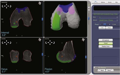
The robotic technology is based on three-dimensional CT images of the patient’s knee. Once a compatible CT scan is obtained, the scan segments are inputted into the robotic computer, and a process called segmentation is performed. In this process each CT image is outlined with a computer probe and the cortical bone shape thus inputted into the computer. The robot then utilizes this information to construct an accurate three-dimensional image of the knee. The Makoplasty technician then uses shape matching to align computer models of the implants to the cortical bone surface, planning for the implants to be approximately 1 mm proud of the bone to mimic the thickness of hyaline cartilage. The computer allows accurate positioning of the implants on the bone, and measures the alignment in relation to the mechanical axis of the extremity as determined from the CT scout views of hip, knee, and ankle.8
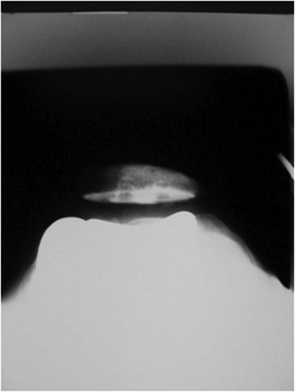
Implant placement of UKA components is based on fairly traditional alignment parameters that can be found in any tome on unicompartmental arthroplasty. Once alignment of the trochlear component is begun, however, positioning parameters are less clear since this is a shape-matching component. The author has had good success with generally matching the cortical shape of the trochlear groove, taking care to deepen the groove slightly to avoid overstuffing the patellofemoral joint. It is very important to pay close attention to the medial and lateral transition zones to assure smooth transition of the patella from the trochlea onto the femoral condylar surface, and thus avoid a “speed bump” effect when the patella tracks through the range of motion (Fig. 14–1).
Operating Room And Patient Setup
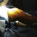
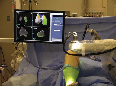
The introduction of any complex technology into the operating room environment always adds its own special problems and difficulties.9 In the case of robotics, there are issues of placement of the robot unit as well as the camera and console for the Makoplasty technician. These items must be placed in an appropriate position near enough to the patient to allow full effectiveness of the robotic arm while still allowing adequate line-of-sight visibility for the optical trackers, and leaving room for the surgeon and assistant to perform the technical aspects of the surgery (Fig. 14–2). The author finds it most effective to place the robot on the side of the table opposite the operated leg, thus bringing the robotic arm into the wound directly from the side of the extremity that carries the incision; for example, for a left medial UKA, the robot would be placed on the right side of the patient and the robotic burr delivered directly into the medial parapatellar incision. The camera and technician console are opposite the robot approximately 5 feet from the table to give the optimal camera view of the optical arrays. The arrays are placed anterolateral so there is an unobstructed view of the camera. Alternative setups can be utilized but limit camera view or robotic access, or allow excess bone debris to be expelled onto the arrays (see Fig. 14–2).
Surgical Approach
For medial or patellofemoral arthritis, a medial parapatellar approach is utilized. The incision begins at the superior pole of the patella and extends to the midtibial tuberosity. A smaller incision may be utilized; however, this makes placement of the high-flex femoral component more difficult. The arthrotomy mimics the skin incision, with care taken to avoid cutting of the vastus medialis muscle. A medial retinacular T-shaped incision is made in the joint capsule midway between the vastus medialis and medial meniscus to allow increased access to the joint and also ease placement of and access to the femoral mechanical checkpoint, placed later in the procedure for reference of the robotic registration.1 The deep fibers of the medial collateral ligament are then elevated, and the infrapatellar fat pad removed. Following this, a thorough examination of the joint should reveal an intact patellofemoral joint, lateral compartment, and ACL for a medial UKA, and isolated patellofemoral arthritis if a PF arthroplasty is the plan. The approach for a lateral UKA mirrors that of the medial, the main difference being that extra care must be taken to avoid retractor placement that puts pressure on the peroneal nerve, located posterior to the fibular head. Also, the surgeon should be extra mindful of landmarks, since the medial approach is more familiar, and when working from the lateral side one can easily become confused and misplace landmarks or malalign a component.
Dynamic Ligament Balancing
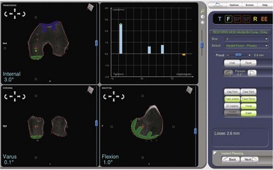
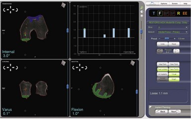
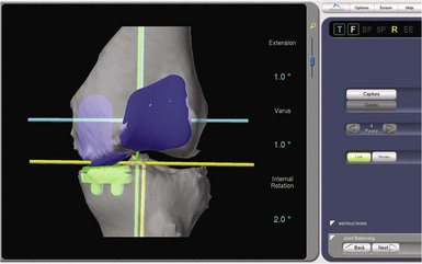
One of the most exciting features of the robotic software is that which allows dynamic ligament balancing of the completed procedure prior to cutting any bone. Once the bones are registered, the knee can be moved through a range of motion, and a series of data points captured while stressing the knee into “anatomic” or corrected alignment. This mimics the final corrected alignment of the knee as best determined by the experienced “feel” of the surgeon. Also, the alignment can be viewed on the computer screen and the limb alignment corrected to neutral, or more commonly slightly undercorrected for the UKA to avoid overloading the contralateral side of the joint; in other words, a varus knee is usually undercorrected to 1° of mechanical varus alignment.7 Once this “ideal” alignment position is determined and recorded by the computer, the implant position can be microadjusted within these ligament parameters until the flexion and extension gaps are perfectly balanced, usually to within 0.1 mm. This ligament-balancing technique leads to excellent ACL function and tension, and very early and rapid return of ROM postoperatively (Figs. 14–3 through 14–5).
Results
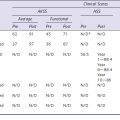
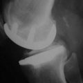
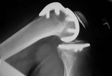
The combination of minimally invasive surgical exposure, minimally traumatic bone removal, and outstanding ligament balance allows rapid postsurgical recovery and very early attainment of ROM goals, increasing patient satisfaction. Additionally, the robotically guided implant alignment leads to excellent postoperative radiographs, thus improving surgeon satisfaction and hopefully long-term implant survival as well (Figs. 14–6 through 14–9).10 The author studied his first 67 robotic-assisted UKAs and compared them to his previous 67 consecutive manually instrumented UKAs. Because of the curved nature of the femoral component, measurements of tibial alignment were taken to test for accuracy of alignment. The root-mean-square (RMS) error of the tibial slope was 3.7° manually compared to 1.2° robotically. In addition, the variance using manual instruments was 9.8 times greater than the robotically guided implantations (p < .0001). In the coronal plane, the average error was 3.0 ± 2.2° more varus using manual instruments compared to 0.3 ± 1.9° when implanted robotically (p < .0001), while the varus/valgus RMS error was 3.7° manually compared to 1.8° robotically. In terms of patient function, patents with either technique had equivalent ROM and Knee Society scores. There was no significant difference in terms of average Knee Society score, change in Knee Society score, or Marmor rating between the two groups at any of the follow-ups. Furthermore, there were no significant differences in the measures that comprise these scores, such as ROM, pain, and use of assistive devices (p > .05), except for ROM at 3 weeks, which was significantly higher for the robotically assisted inlays (116 ± 12) compared to the manual onlays (110 ± 13; p < .01).11,12
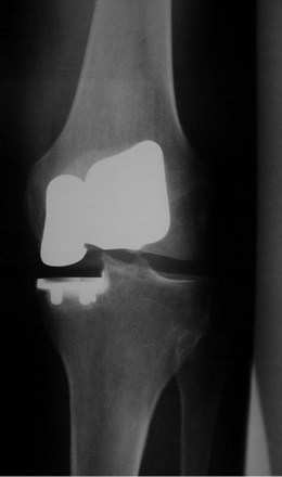
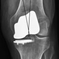
Figure 14–6 Postoperative anteroposterior radiograph of bicompartmental arthroplasty 1 year after surgery.
Bicompartmental arthroplasty is a new addition to the robotic armamentarium. As of the time of this writing, the author has performed approximately 40 such procedures with satisfactory early results—it does remain a procedure under development at this time. Study of the first 15 procedures is ongoing; however, preliminary results at only 6 weeks’ follow-up show patients recovered their preoperative ROM (p = .20). Knee Society Knee Scores significantly improved from a preoperative average of 61 ± 12 (range: 50–90) to a postoperative average at 6 weeks of 87 ± 15 (range: 50–96) (p < .001). Every patient was released after 1 day of hospital stay. Radiographically, there was no evidence of loosening, wear, or progression of osteoarthritis. There were also no perioperative complications.13 Using computer simulation, the amount of bone removed using bicompartmental arthroplasty compared to traditional total knee arthroplasty (TKA) was predicted. Total bone removed on the femur and the tibia using a standard TKA implant is 3.5 times the bone removed using a bicompartmental onlay implant and 4 times the bone removed when using a bicompartmental inlay implant.13
1 Tria AJJr. Advancements in minimally invasive total knee arthroplasty. Orthopedics. 2003;26(8 Suppl):s859-s863.
2 Fisher DA, Watts M, Davis KE. Implant position in knee surgery: a comparison of minimally invasive, open unicompartmental, and total knee arthroplasty. J Arthroplasty. 2003;18(7 Suppl 1):2-8.
3 Kort NP, van Raay JJ, Cheung J, et al. Analysis of Oxford medial unicompartmental knee replacement using the minimally invasive technique in patients aged 60 and above: an independent prospective series. Knee Surg Sports Traumatol Arthrosc. 2007;15:1331-1334.
4 Lonner JH. Indications for unicompartmental knee arthroplasty and rationale for robotic arm-assisted technology. Am J Orthop. 2009;38(2 Suppl):3-6.
5 Banks SA. Haptic robotics enable a systems approach to design of a minimally invasive modular knee arthroplasty. Am J Orthop. 2009;38(2 Suppl):23-27.
6 Lonner JH. Modular bicompartmental knee arthroplasty with robotic arm assistance. Am J Orthop. 2009;38(2 Suppl):28-31.
7 Berger RA, Nedeff DD, Barden RM, et al. Unicompartmental knee arthroplasty: clinical experience at 6–10 year followup. Clin Orthop Relat Res. 1999;367:50-60.
8 Roche MW, O’Loughlin PF, Musahi V, et al. Robot-assisted unicompartmental knee arthroplasty: preoperative planning and surgical technique. Am J Orthop. 2009;38(2 Suppl):10-15.
9 Coon TM. Integrating robotic technology into the operating room. Am J Orthop. 2009;38(2 Suppl):7-9.
10 Lonner JH, John TK, Conditt MA. Robotic arm-assisted UKA improves tibial component alignment: a pilot study. Clin Orthop Relat Res. 2010;468:141-146.
11 Coon TM, Driscoll MD, Horowitz S, et al. Robotic assisted UKA is more accurate than manually instrumented UKA. Podium presentation at the 21st Annual Congress of ISTA, October 1–4, 2008, Seoul, South Korea.
12 Coon TM, Driscoll MD, Conditt MA. Early clinical success of a novel tactile guided UKA technique. Podium presentation at the 21st Annual Congress of ISTA, October 1–4, 2008, Seoul, South Korea.
13 Coon TM, Kreutzer S, Horowitz S, et al. Robotically guided bicompartmental arthroplasty. Podium presentation at the International Society for Computer Assisted Orthopedic Surgery Annual Meeting, June 16–19, 2010, Paris, France.