Chapter 18 Computed tomography


INTRODUCTION
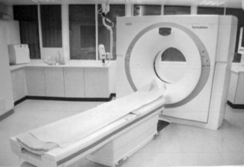
The 1980s saw a significant advancement in technology with the introduction of slip rings, which eliminated the need for a high-tensioncable supply to the X-ray tube and detectors and allowed the X-ray tube to rotate continuously in one direction around the patient. This is known as spiral or helical CT. Slip rings are ‘electromechanical devices consisting of circular electrical conductive rings and brushes that transmit electrical energy across a rotating interface’.1 Slip ring technology was first incorporated into the third generation scanners. The most common type of CT scanner in use today is the fourth generation scanner, incorporating a stationary circular ring of detectors and a large fan beam of X-rays.
SYSTEM COMPONENTS
System components for CT generally fall into four categories:
IMAGING SYSTEM
THE COMPUTER SYSTEM
A mini-computer controls the processing in a CT system. The computer and image processing systems work together and utilise fast processing of data and include a large storage capacity. Thecomputer system receives the numerical data from the DAS and, once the raw data is processed and the process of convolution and back projection have taken place, it assigns a grey scale to the numerical values (grey-scale images are easier for radiologists to interpret than numerical data). These numerical values are known as CT numbers or Hounsfield units (HU), named after Sir Godfrey Hounsfield (1919–2004). CT numbers are related to the linear attenuation coefficient of the tissues within the slice and therefore related to the attenuation of X-rays by the tissues. They are measured using the attenuation of water as a reference, with water assigned the value zero (0). The value for bone is +1000 and for air is −1000, with various soft-tissue types placed somewhere along the scale. These grey-scale images are then sent to the image display system within the scanning control room for the operator to visualise.
IMAGE DISPLAY
| Lung | 1500 and −500 |
| Soft tissue chest | 350 and 50 |
ARTEFACTS
PARTIAL VOLUME
Again, this is much less of a problem now with the widespread use of multi-slice scanners. Partial volumes occur when an object does not fill the entire slice thickness. During image reconstruction it can be difficult for the computer to separate the CT numbers allocated to each tissue type so an average value is given and the resultant object will be poorly visualised on the image. The easiest way to correct this is to use thin slices. A typical body CT scan will use 16 × 1.5 collimation; this data will then be reconstructed to 2 mm slices for the radiologist to report from. A second reconstruction will then be carried at 8 mm and this is what will be either transferred to the PACS system or filmed.
METAL ARTEFACT
The blocking of radiation from the detectors by the metal present causes metal artefacts. Metal artefacts will typically be seen as a star burst effect emanating from the metal (Fig. 18.2).
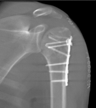
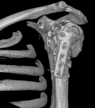
Steps should be taken to remove all external metal objects before scanning. For internal metal, selection of an appropriate algorithm can reduce the effect. Most scanners will also have a specific postprocessing VRT for minimising this even further (Fig. 18.3). This can prove useful when imaging patients after spinal fusion surgery to check the position of the pedicular screws.
PATIENT CARE
The vast majority of patients encountered will be mobile, self-caring outpatients.
PRE-SCAN PREPARATION
Oral contrast
Depending on what type of scan a patient is having they made require oral contrast prior to the scan. Some departments will use positive contrast agents such as barium or gastrografin and others may use negative contrast agents such as water. Oral contrast agents can be administered at any time between 4 hours and 15 min prior to a scan commencing. This information is all dependent on individual departmental scanning protocols.
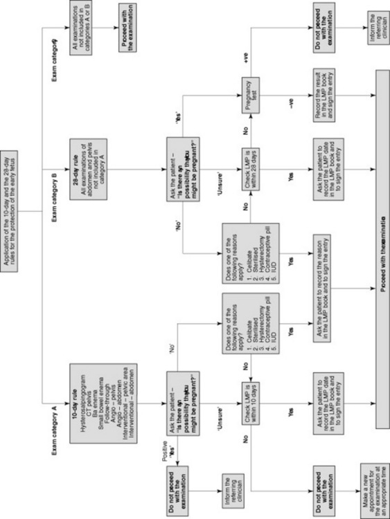
Pregnancy status
It is essential under the IR(ME)R guidelines that when scanning patients of childbearing age (commonly between the ages 12 and 55, but may vary), you must establish a pregnancy status (Fig. 18.4). This should apply to all scans in the region between the diaphragm and the knees.
Scan room care
SCAN PROCEDURE
Scan
With the modern multi-slice scanners available today a typical scan will take on average 25–30 seconds with breath-holds usually lasting no longer than 30 seconds. Whilst the scanner is performing the scan, the scan table will move through the gantry and the reconstructed images will appear on the monitor. This process occurs extremely quickly. It is advisable to watch thepatient during the scan, especially if intravenous contrast is being administered via a pump injector, to ensure that the contrast appears to be flowing correctly and that the patient does not have an immediate reaction to the contrast. If post-scan reconstructions are required these can be performed once the patient has left the scan room or while you are removing the patient from the table. At this stage patient care is important; therefore, if it is required that scans are checked by a radiologist before the patient leaves, ensure you make the patient comfortable by lowering the patient’s arms to a natural position and giving information on what is happening. If the patient has had a scan with intravenous contrast and is leaving the department to go home, ensure you correctly remove any cannula in the patient’s arm by applying pressure to the area and then dispose of the sharp into a sharps bin.
Seeram E. Computed tomography: physical principles, clinical applications, and quality control, 2nd edn. London: WB Saunders, 2001.
This text provides discussion of all aspects of CT physics to include multislice applications..
Jackson S, Thomas R. Cross-sectional imaging made easy. Oxford: Churchill Livingstone, 2004.


