[level-membership-for-cardiovascular-category]
CHAPTER 9 Clinical Techniques of Cardiac Computed Tomography
PATIENT PREPARATION
Electrocardiogram (ECG) leads need to be attached, which are used by the scanner to determine data reconstruction and electrocardiographic tube modulation, if used. In addition, this allows monitoring of the patient for absolute heart rate, heart rate variability, and arrhythmias, which are critical in determining the optimum protocol. A good electrocardiographic tracing (Fig. 9-1) is required, especially if using electrocardiographic tube modulation for overall dose reduction, because the x-ray tube modulation is synchronized with the cardiac cycle, using the R wave as a reference. It is important to ensure that the wire leads and ECG patches are outside the scanning field as much as possible, and in particular to ensure that the wires are not coiled on the patient’s chest, which can result in significant streak artifact. For someone who is very hairy, good adherence and electrical conductivity of the pads may require shaving a small area. In particular, noisy electrocardiographic tracings (Fig. 9-2) can lead to inappropriate modulation of the tube current, resulting in a poor signal-to-noise ratio at the specific phase of the cardiac cycle required for coronary evaluation. In addition, be sure that the R wave peak is of greater amplitude compared with the T wave to prevent tube current modulation synchronized to the wrong phase of the cardiac cycle. Some scanners allow switching of the lead at the scanner console; if not, manual switching of the lead attachments to the ECG patches on the patient can often correct a situation in which the T wave has a higher peak.
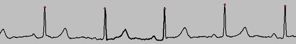
 FIGURE 9-1 Good electrocardiographic tracing with clean R wave peaks and essentially no baseline noise.
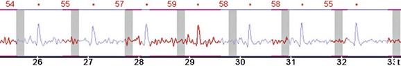
 FIGURE 9-2
If the patient’s baseline heart rate is above an acceptable limit for optimal image quality, the use of β blockers is recommended, provided no contraindications (e.g., asthma, aortic stenosis) are present.1 This acceptable limit is increasing with the latest generation of scanners. However, with the current generation of 64-slice scanners, a heart rate below 65 beats/min is highly recommended to increase the likelihood of an optimal high-quality scan with the least amount of motion artifact. There are multiple protocols for the administration of β blockers. The two basic protocols include the use of oral administration, both the night before and the morning of the scan, or just the morning of the scan, versus intravenous (IV) administration just prior to the scan.1 In general, oral administration seems to result in a more predictable result, and it also requires less time and personnel commitment from the support staff. However, IV administration can be effective if the patient did not have prior administration of an oral β blocker or the target heart rate was not achieved after the administration of an oral dose. IV administration tends to have an all or none effect, meaning that usually if there is a noticeable decrease in heart rate with the first dose administered, a desired heart rate can usually be achieved. However, in many patients, the maximum dose (25 mg metoprolol at our institution) is administered without a noticeable change in heart rate. If the patient’s heart rate does not reach the target, then the scan can be obtained with the understanding that it will likely be suboptimal, with the potential for nonevaluable segments of the coronary arteries, or the patient can be rescheduled with more aggressive oral β blocker administration prior to the scan.
A baseline heart rate and blood pressure are documented. Then, a brief history is obtained from the patient, including contraindications to the medications that will be administered for the examination, which may include a beta blocker and nitroglycerin. The patient is questioned about history of asthma, heart failure, and heart murmur with respect to β blockers and erectile dysfunction medications, and sildenafil with respect to nitroglycerin. Nitroglycerin is administered to dilate the coronary arteries for optimal visualization.2 If there are no contraindications, the medications to be administered for the examination include up to 25 mg of metoprolol IV, in 5-mg push increments, and two 0.4-µg sublingual tablets. The onset of action for a sublingual nitroglycerin tablet is 1 to 3 minutes; it reaches maximum effect at 5 minutes, lasting at least 25 minutes. Therefore, these will be administered just prior to the scout and coronary CTA will be performed at approximately 5 to 6 minute after administration.
SCANNING TECHNIQUE
Image Quality
There are many factors that affect the image quality of cardiac CT examinations. With each generation of CT scanner release, the image quality has improved, mainly because of two elements—spatial and temporal resolution. Spatial resolution improved significantly with 4-, 16-, and 64-slice scanners. In addition to improvement in the actual spatial resolution of a single detector in the detector array, there is now also the ability to obtain high-resolution images using the entire detector array, resulting in an overall faster scan time. This results in significantly shorter breath-holds required by the patients and therefore better compliance and reproducibility of the scans. Temporal resolution is most affected by the gantry rotation time. With each generation of scanner, the gantry rotation times have improved, currently achieving 270 ms. With slow heart rates, the temporal resolution of the images is approximately half that of one gantry rotation time (e.g., with a 270-ms gantry rotation time, the temporal resolution would 135 ms). As a comparison, electron beam CT (EBCT) has a temporal resolution of 50 to 100 ms,3 and usually in cardiac MRI, the temporal resolution is less than 50 ms.4 Cardiac catheterization with a temporal resolution less than 20 ms is the best modality for imaging coronary arteries with respect to temporal resolution.5 So, even though temporal resolution has significantly improved, there is still a potential for more improvement. The manufacturers, however, have been able to reduce the temporal resolution of images when the heart rate is more than 65 beats/min. By combining data from at least two different detector elements along the detector array from at least two different physical cardiac cycles, but from the same anatomic location and same phase of the cardiac cycle, an image can be created with an improved temporal resolution approaching 35 ms (four-phase reconstruction; gantry rotation = 270 ms). However, combining two different physical cardiac cycles introduces inherent motion artifact.6 There must be a balance between combining data from different physical heartbeats and trying to improve temporal resolution.
Contrast Administration
The IV contrast is administered through an 18-gauge angiocatheter in the antecubital fossa. IV access is preferably via the right arm, which helps prevent significant streak artifact from the dense inflow of contrast, especially when scanning to the level of the aortic arch for evaluation of aortic pathology or the origin of coronary artery bypass grafts (in particular, the left internal mammary). To ensure adequate IV access, consider training CT technologists to place the angiocatheter under ultrasound guidance. We also use a trapeze, which helps keep the patient’s arms straight, thus helping to prevent complications of high-flow injections. We also find it more comfortable for our older patients, who frequently have shoulder disabilities that make it difficult for them to place their arms above their head. The trapeze has 10 pounds of weight at the other end, helping to hold the patient’s arms comfortably in an extended position, out of the way of the scan (Fig. 9-3).
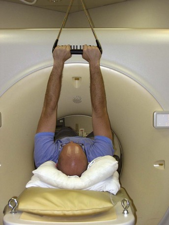
 FIGURE 9-3
The contrast is administered using a test bolus or a track and trigger technique. Briefly, the test bolus system injects a 20-mL bolus of contrast followed by 20 to 40 mL of saline push at the same injection rate planned for the coronary CTA scan. Intermittent low-dose images are obtained at the level of the carina, beginning approximately 10 seconds after the start of injection and are acquired every 1 to 2 seconds, until the peak of contrast has been demonstrated in the ascending aorta.7 The images are loaded into an analysis software application on the scanner, which determines the time of peak contrast enhancement. The coronary CTA scan is then obtained with the full dose of contrast administered and the scan acquisition timing determined according to peak enhancement. The scan acquisition is usually planned to begin approximately 2 to 4 seconds after the peak enhancement determined from the test bolus to allow stabilization of the enhancement curve prior to scanning. This was an important technique in the past, especially with the slower scanners and longer breath-holds required for coronary CTA examinations (40 seconds on a four-slice scanner). With the faster scanners today having scan times as short as 4 to 5 seconds on a 256-slice scanner, a track and trigger technique can result in excellent opacification, without the need for the additional 20 mL of contrast of the test bolus. Therefore, coronary CTA with the track and trigger technique on the 256-slice scanner can be performed with as little as 50 mL of contrast.
Tube Modulation to Minimize Radiation Dose
If the patient has the desired slow heart rate (<65 beats/min) and is in normal sinus rhythm without arrhythmias, then electrocardiographic tube modulation should be used to minimize radiation dose. This allows the x-ray tube to modulate the tube current (mA) in synchronization with the cardiac cycle. This technique can only be used during a retrospective electrocardiographic gated scan; with an appropriately slow heart rate, it can result in a dose reduction of up to 50%. As the heart rate increases, there is less dose savings, because the tube has less chance to reach minimum output. Once a heart rate of approximately 85 to 90 beats/min is reached, there is no dose savings, because the tube cannot modulate fast enough. The tube will be at maximum current during late diastole and minimum current during systole because in general the best reconstructed phase to evaluate the coronary arteries is a late diastolic phase.8 If a step and shoot technique is used, the x-ray tube is turned on and off between each step and image acquisition. It is not a helical technique but an axial technique, with data acquired only at discrete anatomic steps and only during predefined portions of the cardiac cycle. This significantly reduces the radiation dose; however, it does not allow for capture of the full cardiac cycle, thus eliminating the data required to evaluate valve and overall cardiac function. It also allows only visualization of the heart during the predefined portion of the cardiac cycle. If based on heart rate, therefore, a systolic reconstruction would result in better images of the RCA,9 images that would be unavailable using this technique if the predefined phase of scanning were in the late diastolic phase. However, with the retrospective technique, even if electrocardiographic tube modulation were used, the images could be reconstructed at any phase of the cardiac cycle at any anatomic location, even though the images reconstructed during systole would have a poor signal-to-noise ratio.
POSTPROCEDURAL CONSIDERATIONS
Once the scan is complete, if everything has gone well, there will be optimal quality images, resulting in easier interpretation. First, review the electrocardiographic tracing to be sure that no arrhythmias occurred during the scan that will require editing for optimization of the data set. Next, pan and zoom the images to optimize spatial resolution for viewing the coronary arteries. Keep in mind that with a standard 512 × 512 matrix, the smaller the field of view, the better the spatial resolution will be, which is paramount in coronary artery evaluation. In general, reconstructed axial images should be 0.6 to 0.9 mm thick, with a 50% increment (0.3 to 0.45 mm). If performing stent evaluations, the thinnest possible slice thickness with a 50% increment is recommended, combined with a sharp kernel or filter.10,11 It is usually helpful to reconstruct three coronary data sets, including the phase of the R-R interval, which is usually optimal, as well as ±5% around this phase of the cardiac cycle. Depending on the scanner manufacturer, this may be 60% to 65% to 70% or 70% to 75% to 80%. It should be noted that there is a difference in manufacturer definition of the percentage of the R-R interval, either defining it based on the beginning of the temporal window or at the center of the temporal window. At a heart rate of 60 beats/min, this results in approximately a 10% shift, depending on how the phase is defined (i.e., 65% vs. 75%). In addition, if there is motion in the right coronary artery, a systolic reconstruction may be beneficial (e.g., 35% or 40%).9 A multiphase data set of 5% to 95% every 10% is also reconstructed, with a slice thickness of 1.5 mm and increment of 1.5 mm; this is used for valve evaluation and qualitative and quantitative cardiac functional analysis. Finally, a full field of view data set can be created, which includes all soft tissues from skin to skin along the z-axis coverage of the scan, to evaluate for incidental findings, which may be the source of the patient’s chest pain. These are reconstructed using a routine chest CT protocol such as 4-mm slice thickness with a 3-mm increment.
With the current generation of software on a dedicated workstation, it is fairly easy and accurate to determine cardiac function using the multiphase data set.12 Curved multiplanar reconstructions (MPRs) of the coronary arteries are also created and stored on the picture archiving and communication system, which is very helpful in communicating the findings to referring physicians.
As for image interpretation, this is almost exclusively performed on a dedicated workstation. There are multiple software packages and techniques available for image interpretation, but those with the most experience tend to use the full axial data sets combined with interactive MPR and maximal intensity projection (MIP) visualization when a lesion is identified. This has been found by at least one study to be the most accurate method of image interpretation, as opposed to prerendered curved MPRs or vessel view technique.13 Creating a structured report is highly encouraged.14 The recommended method of reporting coronary narrowing and stenosis is based on visual inspection without noting specific diameter or area narrowing measurements because generally the CT technique overestimates the narrowing compared with coronary angiography.
Pitfalls and Solutions: Artifacts
Breathing artifacts are easily recognized by stair-step artifacts in the sternum (Fig. 9-4). There are essentially no techniques during postprocessing that will compensate for breathing artifacts. If there is gross movement of the patient during the scan, the sternum and spine will have stair-step artifacts.
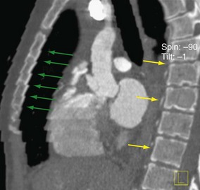
 FIGURE 9-4
If there are stair-step artifacts in the heart but not in the sternum or spine, this is consistent with a synchronization and data reconstruction issue, referred to as electrocardiographic misregistration (Fig. 9-5). In this situation, the images can be significantly improved by editing the tagging of the electrocardiographic tracing. This may be a result of an arrhythmic beat, which can be completely ignored (Fig. 9-6), or it may be caused by inappropriate R wave tagging by the scanner either tagging a T wave or putting in false R wave tags caused by a noisy electrocardiographic tracing (Fig. 9-7). Once the ECG has been corrected, the images often are at the least diagnostic and frequently are of high quality.
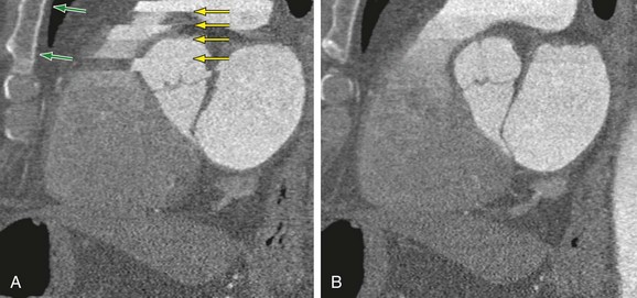
 FIGURE 9-5
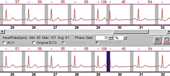
 FIGURE 9-6
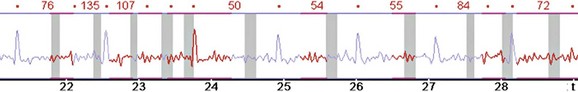
 FIGURE 9-7

Desjardins B, Kazerooni EA. ECG-gated cardiac CT. AJR Am J Roentgenol. 2004;182:993-1010.
Flohr TG, Raupach R, Bruder H. Cardiac CT: how much can temporal resolution, spatial resolution, and volume coverage be improved? J Cardiovasc Comput Tomogr. 2009;3:143-152.
Flohr TG, Schoepf UJ, Ohnesorge BM. Chasing the heart: new developments for cardiac CT. J Thorac Imaging. 2007;22:4-16.
Kaira MK, Brady TJ. Current status and future directions in technical developments of cardic computed tomography. J Cardiovasc Comput Tomogr. 2008;2:71-80.
Kerl JM, Hofmann LK, Thilo C, et al. Coronary CTA: image acquisition and interpretation. J Thorac Imaging. 2007;22:22-34.
Lawler LP, Pannu HK, Fishman EK. MDCT evaluation of the coronary arteries, 2004: how we do it—data acquisition, postprocessing, display, and interpretation. AJR Am J Roentgenol. 2005;184:1402-1412.
Lesser JR, Flygenring BJ, Knickelbine T, et al. Practical approaches to overcoming artifacts in coronary CT angiography. J Cardiovasc Comput Tomogr. 2009;3:4-15.
Mayo JR, Leipsic JA. Radiation dose in cardiac CT. AJR Am J Roentgenol. 2009;192:646-653. Erratum 2009; 192:1167
Pannu HK, Alvarez WJr, Fishman EK. Beta-blockers for cardiac CT: a primer for the radiologist. AJR Am J Roentgenol. 2006;186:S341-S345.
Ramkumar PG, Mitsouras D, Feldman CL, et al. New advances in cardiac computed tomography. Curr Opin Cardiol. 2009;24:596-603.
1 Pannu HK, Alvarez WJr., Fishman EK. Beta-blockers for cardiac CT: a primer for the radiologist. AJR Am J Roentgenol. 2006;186:S341-S345.
2 Dewey M, Hoffmann H, Hamm B. Multislice CT coronary angiography: effect of sublingual nitroglycerine on the diameter of coronary arteries. Rofo. 2006;178:600-604.
3 McCullough CH. Principles and performance of electron beam computed tomography. In: Fowlkes JB, editor. Medical CT and Ultrasound: Current Technology and Applications. Madison, Wis: Advanced Medical; 1995:411-436.
4 Boxerman JL, Mosher TJ, McVeigh ER, et al. Advanced MR imaging techniques for evaluation of the heart and great vessels. Radiographics. 1998;18:543-564.
5 Goldberg HL, Moses JW, Fisher J, et al. Diagnostic accuracy of coronary angiography utilizing computer-based digital subtraction methods. Comparison to conventional cineangiography. Chest. 1986;90:793-797.
6 Halliburton SS, Stillman AE, Flohr T, et al. Do segmented reconstruction algorithms for cardiac multi-slice computed tomography improve image quality? Herz. 2003;28:20-31.
7 Moloo J, Shapiro MD, Abbara S. Cardiac computed tomography: technique and optimization of protocols. Semin Roentgenol. 2008;43:90-99.
8 Herzog C, Arning-Erb M, Zangos S, et al. Multi-detector row CT coronary angiography: influence of reconstruction technique and heart rate on image quality. Radiology. 2006;238:75-86.
9 Kopp AF, Schroeder S, Kuettner A, et al. Coronary arteries: retrospectively ECG-gated multi-detector row CT angiography with selective optimization of the image reconstruction window. Radiology. 2001;221:683-688.
10 Maintz D, Seifarth H, Flohr T, et al. Improved coronary artery stent visualization and in-stent stenosis detection using 16-slice computed-tomography and dedicated image reconstruction technique. Invest Radiol. 2003;38:790-795.
11 Suzuki S, Furui S, Kaminaga T, et al. Evaluation of coronary stents in vitro with CT angiography: effect of stent diameter, convolution kernel, and vessel orientation to the z-axis. Circ J. 2005;69:1124-1131.
12 Savino G, Zwerner P, Herzog C, et al. CT of cardiac function. J Thorac Imaging. 2007;22:86-100.
13 Ferencik M, Ropers D, Abbara S, et al. Diagnostic accuracy of image postprocessing methods for the detection of coronary artery stenoses by using multidetector CT. Radiology. 2007;243:696-702.
14 Stillman AE, Rubin GD, Teague SD, et al. Structured reporting: coronary CT angiography: a white paper from the American College of Radiology and the North American Society for Cardiovascular Imaging. J Am Coll Radiol. 2008;5:796-800.
[/level-membership-for-cardiovascular-category][not-level-membership-for-cardiovascular-category]
CHAPTER 9 Clinical Techniques of Cardiac Computed Tomography
PATIENT PREPARATION
Electrocardiogram (ECG) leads need to be attached, which are used by the scanner to determine data reconstruction and electrocardiographic tube modulation, if used. In addition, this allows monitoring of the patient for absolute heart rate, heart rate variability, and arrhythmias, which are critical in determining the optimum protocol. A good electrocardiographic tracing (Fig. 9-1) is required, especially if using electrocardiographic tube modulation for overall dose reduction, because the x-ray tube modulation is synchronized with the cardiac cycle, using the R wave as a reference. It is important to ensure that the wire leads and ECG patches are outside the scanning field as much as possible, and in particular to ensure that the wires are not coiled on the patient’s chest, which can result in significant streak artifact. For someone who is very hairy, good adherence and electrical conductivity of the pads may require shaving a small area. In particular, noisy electrocardiographic tracings (Fig. 9-2) can lead to inappropriate modulation of the tube current, resulting in a poor signal-to-noise ratio at the specific phase of the cardiac cycle required for coronary evaluation. In addition, be sure that the R wave peak is of greater amplitude compared with the T wave to prevent tube current modulation synchronized to the wrong phase of the cardiac cycle. Some scanners allow switching of the lead at the scanner console; if not, manual switching of the lead attachments to the ECG patches on the patient can often correct a situation in which the T wave has a higher peak.
FIGURE 9-1 Good electrocardiographic tracing with clean R wave peaks and essentially no baseline noise.
If the patient’s baseline heart rate is above an acceptable limit for optimal image quality, the use of β blockers is recommended, provided no contraindications (e.g., asthma, aortic stenosis) are present.1 This acceptable limit is increasing with the latest generation of scanners. However, with the current generation of 64-slice scanners, a heart rate below 65 beats/min is highly recommended to increase the likelihood of an optimal high-quality scan with the least amount of motion artifact. There are multiple protocols for the administration of β blockers. The two basic protocols include the use of oral administration, both the night before and the morning of the scan, or just the morning of the scan, versus intravenous (IV) administration just prior to the scan.1 In general, oral administration seems to result in a more predictable result, and it also requires less time and personnel commitment from the support staff. However, IV administration can be effective if the patient did not have prior administration of an oral β blocker or the target heart rate was not achieved after the administration of an oral dose. IV administration tends to have an all or none effect, meaning that usually if there is a noticeable decrease in heart rate with the first dose administered, a desired heart rate can usually be achieved. However, in many patients, the maximum dose (25 mg metoprolol at our institution) is administered without a noticeable change in heart rate. If the patient’s heart rate does not reach the target, then the scan can be obtained with the understanding that it will likely be suboptimal, with the potential for nonevaluable segments of the coronary arteries, or the patient can be rescheduled with more aggressive oral β blocker administration prior to the scan.
A baseline heart rate and blood pressure are documented. Then, a brief history is obtained from the patient, including contraindications to the medications that will be administered for the examination, which may include a beta blocker and nitroglycerin. The patient is questioned about history of asthma, heart failure, and heart murmur with respect to β blockers and erectile dysfunction medications, and sildenafil with respect to nitroglycerin. Nitroglycerin is administered to dilate the coronary arteries for optimal visualization.2 If there are no contraindications, the medications to be administered for the examination include up to 25 mg of metoprolol IV, in 5-mg push increments, and two 0.4-µg sublingual tablets. The onset of action for a sublingual nitroglycerin tablet is 1 to 3 minutes; it reaches maximum effect at 5 minutes, lasting at least 25 minutes. Therefore, these will be administered just prior to the scout and coronary CTA will be performed at approximately 5 to 6 minute after administration.
SCANNING TECHNIQUE
Image Quality
There are many factors that affect the image quality of cardiac CT examinations. With each generation of CT scanner release, the image quality has improved, mainly because of two elements—spatial and temporal resolution. Spatial resolution improved significantly with 4-, 16-, and 64-slice scanners. In addition to improvement in the actual spatial resolution of a single detector in the detector array, there is now also the ability to obtain high-resolution images using the entire detector array, resulting in an overall faster scan time. This results in significantly shorter breath-holds required by the patients and therefore better compliance and reproducibility of the scans. Temporal resolution is most affected by the gantry rotation time. With each generation of scanner, the gantry rotation times have improved, currently achieving 270 ms. With slow heart rates, the temporal resolution of the images is approximately half that of one gantry rotation time (e.g., with a 270-ms gantry rotation time, the temporal resolution would 135 ms). As a comparison, electron beam CT (EBCT) has a temporal resolution of 50 to 100 ms,3 and usually in cardiac MRI, the temporal resolution is less than 50 ms.4 Cardiac catheterization with a temporal resolution less than 20 ms is the best modality for imaging coronary arteries with respect to temporal resolution.5
[/not-level-membership-for-cardiovascular-category]
