Chapter 4 Clinical Methods
Ultrasound Biomicroscopy
Introduction
Ultrasound biomicrosopy (UBM) utilizes high frequency ultrasound to evaluate anterior ocular structures (Chapter 2).1–5 As in the examination of the posterior segment with B-scan and A-scan, the specific type of examination performed is determined by the indication for examination. UBM has numerous clinical applications, particularly in the evaluation of corneal diseases (Chapter 8), glaucoma (Chapter 9), anterior segment tumors (Chapter 11), and trauma (Chapter 16). Modified UBM is also increasingly used for measurements of organs in laboratory animals (Chapter 17). Digital UBM is an important tool in assessment of patients undergoing refractive surgical procedures (Chapter 6). This chapter describes the methods for performing ultrasound biomicroscopy.
Basic positioning and patient preparation
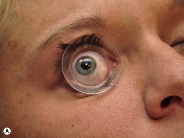
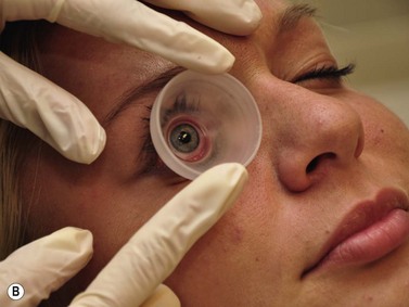
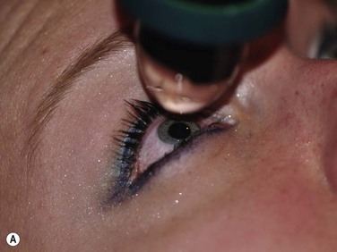
Positioning of the patient for UBM examination is similar to that of contact B-scan and diagnostic A-scan in the evaluation of the posterior segment. It is recommended to recline the patient to the supine position and place an anesthetic drop in the eye to be examined. A fluid immersion technique is necessary to provide the stand-off distance required to view the anterior ocular structures. Specially designed immersion UBM scleral shells are most commonly used to hold the eyelids open and provide a reservoir for the coupling agent (Figure 4.1).1 Water is most easily used in the shells as a coupling agent; however, fluid loss and air bubble obstruction during the procedure can hinder the efficiency of the examination. Methylcellulose is a good alternative because it has low sound attenuation and greater viscosity, preventing fluid loss during the examination.
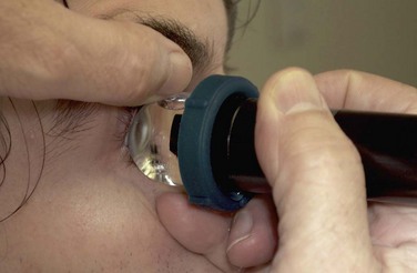
The UBM probe does not have a membrane over the probe tip covering the moving transducer (Chapter 2). Such a membrane would cause significant sound attenuation at the high frequencies used. Therefore, the examiner must be extremely careful to avoid contact with the cornea. Recently, a single use ultrasound cover, ClearScan® has been developed.6 It consists of an extremely thin acoustically invisible film that can be filled with water and placed over the probe tip of the UBM (Figure 4.2). It protects the cornea from the moving transducer, and allows for a thorough examination without the discomfort and peripheral examination constraints of a scleral shell.
UBM probe positions
A typical, 50 mHz UBM probe has a penetration depth of approximately 5.0 mm and a resolution of 37 µm. The relationship of the probe position and display image for the UBM is different than that of the conventional contact B-scan. During UBM examination, the probe is placed directly over the anterior ocular structures to be imaged. Structures that are closest to the probe tip are at the top of the screen, those farthest away are at the bottom (Figure 4.3). The cornea, iris, and lens can be imaged in any plane. The conjunctiva, anterior sclera, ciliary body, and ora can be imaged by adjusting the patient’s gaze 180° away from the clock hour of interest. The top of the UBM display screen corresponds to the front of the transducer. There is a marker along the side of the probe that indicates the movement of the transducer in the same plane as the marker. The far left of the display screen corresponds to the area at the top of the transducer movement and the far right of the display screen corresponds to the bottom of the transducer movement.
Axial scans
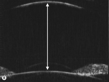
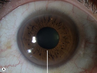
The axial scan is obtained by placing the probe perpendicular to the cornea directly over the pupil. The resulting image shows the cornea and central iris on the left of the display screen, the central cornea and pupil in the center, and the cornea and central iris 180° away from the probe marker on the right. The probe marker is always oriented towards the superior or nasal hemispheres. The axial scan is ideal for accessing the anterior chamber depth and the orientation of displaced or tilted intraocular lenses (Chapter 8) (Figure 4.4).7

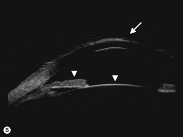
Radial (longitudinal) scans
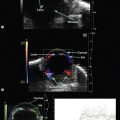
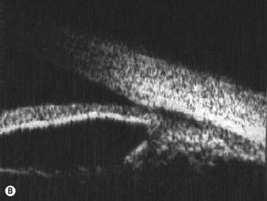
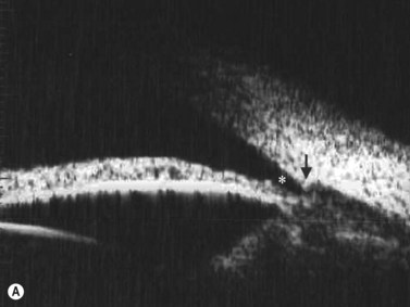
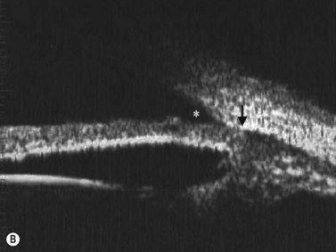
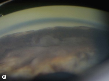
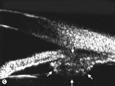
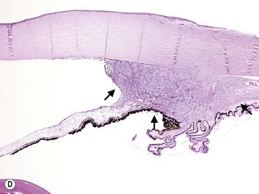
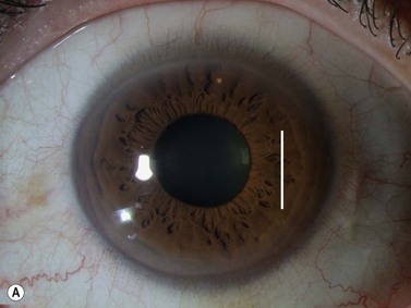
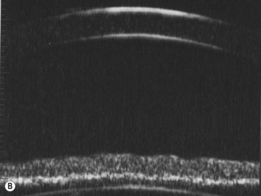
The radial scan is obtained by placing the probe perpendicular to the limbus with the marker towards the pupil. The left side of the display screen corresponds to the cornea and central iris, while the right side corresponds to the limbus and sclera (Figure 4.5). Radial scans most closely resemble the longitudinal scans obtained in 10 MHz, B-scan ultrasonography and are thus labeled as longitudinal scans at the clock hour examined. For example, a radial scan at 6 o’clock is labeled a longitudinal scan of 6 o’clock, or L6. The longitudinal scan is the most common scan used in UBM examinations. The anterior angle is well imaged and the scleral spur easily identifiable. Angle closure can be detected, narrow angles measured and ciliary body orientation evaluated with this technique (Figure 4.6).2,7 The anterior to posterior extent of mass lesions of the iris and ciliary body are also best imaged with this scan (Figure 4.7).8,9
Transverse scans
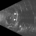
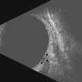
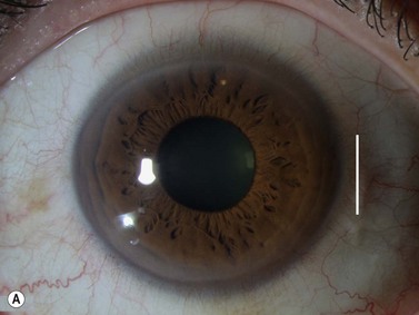
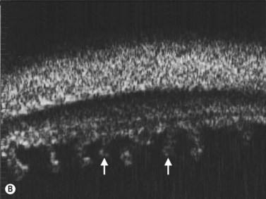
The transverse scan is obtained by placing the probe parallel to the limbus over the central iris at the clock hour of interest. The probe marker is oriented towards the superior or nasal hemispheres. The resulting display image shows a section of the cornea and central iris of approximately 20° (Figure 4.8). To image peripheral structures, the probe can be then shifted posteriorly towards the fornix to image the peripheral iris, ciliary body processes, pars plana, and ora. The scans are labeled according to the clock hour examined. For example if the probe is placed at 3 o’clock overlapping the peripheral iris, the scan is labeled a transverse scan of the iris at 3 o’clock, or T3-iris. It is essential that the probe marker remains parallel to the limbus during all movements to avoid oblique angles that may result in misleading scans. The transverse scan is ideal for the evaluation of the lateral extent of iris and ciliary body masses and for the evaluation of ciliary body processes (Figure 4.9).10
1 Pavlin CJ. Practical application of ultrasound biomicroscopy. Can J Ophthalmol. 1995;30(4):225-229.
2 Pavlin CJ, Foster FS. Ultrasound biomicroscopy. High-frequency ultrasound imaging of the eye at microscopic resolution. Radiol Clin N Am. 1998;36(6):1047-1058.
3 Foster FS, Pavlin CJ, Harasiewicz KA, et al. Advances in ultrasound biomicroscopy. Ultrasound Med Biol. 2000;26(1):1-27.
4 Bryne S, Green R. Ultrasound of the Eye and Orbit, 2nd ed. St. Louis: Mosby; 2002.
5 Silverman RH. High-resolution ultrasound imaging of the eye – a review. Clin Exp Ophthalmol. 2009;37(1):54-67.
6 Bell NP, Feldman RM, Zou Y, et al. New technology for examining the anterior segment by ultrasonic biomicroscopy. J Cataract Refract Surg. 2008;34(1):121-125.
7 Mura JJ, Pavlin CJ, Condon GP, et al. Ultrasound biomicroscopic analysis of iris-sutured foldable posterior chamber intraocular lenses. Am J Ophthalmol. 2010;149(2):245-252. e242
8 Pavlin CJ, McWhae JA, McGowan HD, et al. Ultrasound biomicroscopy of anterior segment tumors. Ophthalmology. 1992;99(8):1220-1228.
9 Vasquez LM, Pavlin CJ, McGowan H, et al. Ring melanoma of the ciliary body: clinical and ultrasound biomicroscopic characteristics. [Erratum appears in Can J Ophthalmol 2008;43(3):378 Note: Yucel, Yeni [added]] Can J Ophthalmol. 2008;43(2):229-233.
10 da Costa DS, Lowder C, de Moraes HVJr, et al. [The relationship between the length of ciliary processes as measured by ultrasound biomicroscopy and the duration, localization and severity of uveitis]. Arqu Bras Oftalmol. 2006;69(3):383-388.