Chapter 3 Clinical Methods
A- and B-Scans

Introduction
Ophthalmic ultrasonography examination techniques are designed to evaluate all aspects of the globe in a methodical, reproducible manner.1–14 The specific type of examination performed is determined by the indication for examination. Contact B-scan and diagnostic A-scan are most commonly used to evaluate the posterior globe and orbit. Anterior ocular structures can be evaluated with a modified immersion B-scan examination, but are most commonly evaluated with ultrasound biomicroscopy (Chapter 4). This chapter describes the proper methods for performing A- and B-scans.
Basic positioning and patient preparation
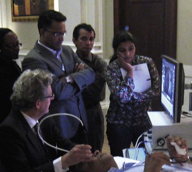
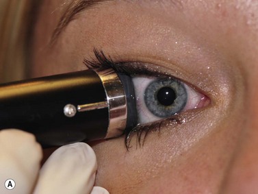
Optimal positioning of the patient and the ultrasound display monitor significantly aids in the ease of obtaining and evaluating captured images. In most cases, scanning the eye with contact B-scan and diagnostic A-scan is most effective if performed with the patient in the reclined position. The ultrasonographer is positioned to the patient’s right or left side at the examiner’s discretion. The ultrasound display monitor and the patient’s head should be located parallel and in close proximity to each other to allow for simultaneous viewing of the ultrasound probe position on the eye and the display monitor (Figure 3.1).
B-scan probe
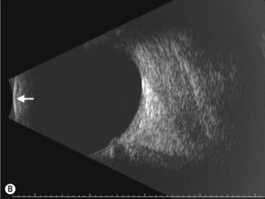
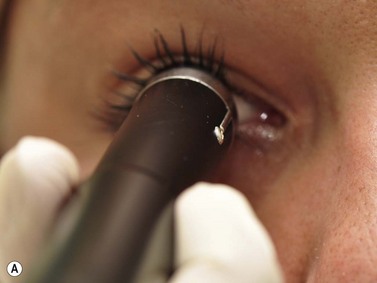
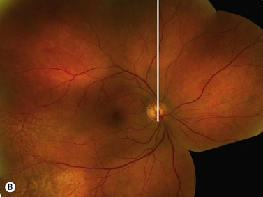
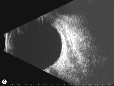
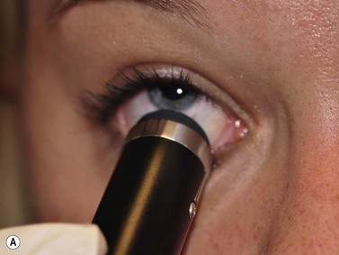
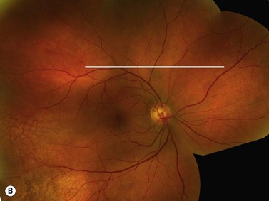
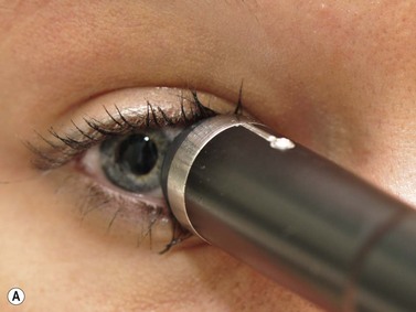
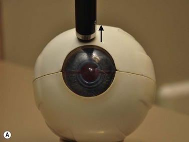
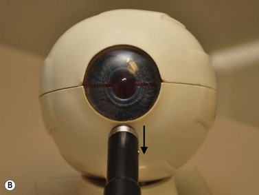
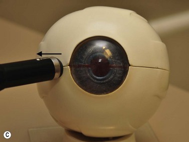
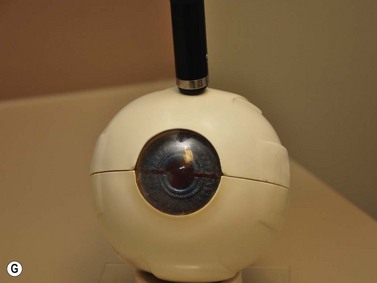
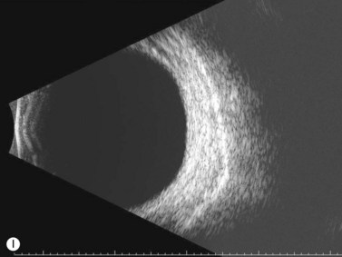
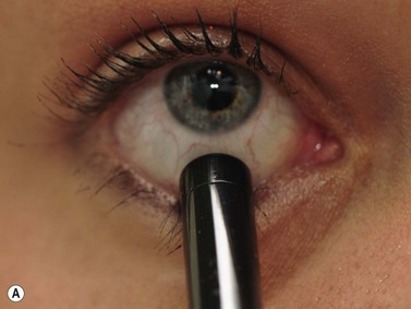
The B-scan probe is a two-dimensional echo display that is used to determine the topographic features of posterior segment pathology including location, shape and extent of lesions (Chapter 2) See Clip 3.1. B-scan probes have a marker along the side of the probe close to the probe tip that indicates the top of the B-scan ultrasound display (Figure 3.2A). The transducer inside the B-scan probe oscillates along the plane of the marker only, towards the marker and away from the marker. Therefore, the top of the B-scan display corresponds to the area indicated on the marker and the bottom of the display corresponds to the plane 180° away from the marker. The probe tip corresponds to the white line on the far left side of the B-scan display. The echoes to the right of this line correspond to the ocular structures opposite the probe tip. The further right the ocular structure, the further away is its echo (Figure 3.2B).
B-scan probe positions
Transcorneal scans
Axial scans
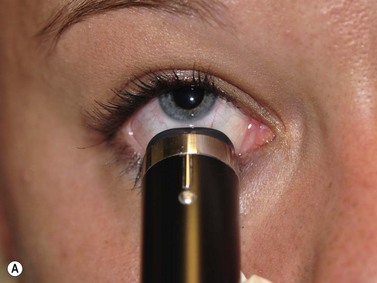
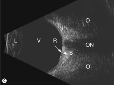
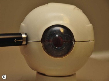
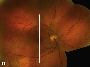
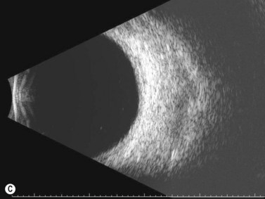
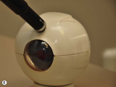
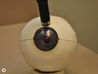
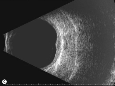
The axial scan is obtained by placing the B-scan probe tip directly over the cornea while the patient looks in primary gaze (Figure 3.3) See Clip 3.2. The resulting image shows the posterior segment of the globe where the marker tip is at the top of the B-scan display, the crystalline lens and the optic nerve in the center and the portion of the globe 180° degrees from the marker at the bottom of the screen. The axial scan is the easiest scan to interpret because the lens and the optic nerve are centered in the image. However, several issues make this scan less than ideal. There is significant sound attenuation and refraction as a result of going through the crystalline lens showing a diminished resolution in the B-scan image. In pseudophakic eyes, the intraocular lens causes intense sound reverberation echoes obstructing most views to the posterior segment. However, the axial scan can be very helpful in the evaluation of some specific disorders affecting the macula (Chapter 10), Tenon’s space (Chapter 12), and the optic nerve (Chapter 13).

Axial scans are always obtained with the probe marker facing upward or horizontally.12 The vertical axial scan is obtained with the marker in the upright position toward 12 o’clock and the horizontal axial scan is obtained with the marker nasally. For oblique axial scans the probe marker is facing toward the upper of the two meridians being examined.
Para-axial scans
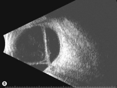
Para-axial scans can be helpful in the evaluation of the peripapillary fundus. The para-axial scan images the fundus directly adjacent to the optic nerve. To obtain the scan, the probe tip is placed directly over the cornea as in the axial scan; however, the sound beam is shifted slightly to the peripapillary area of interest. The sound beam is directed through a portion of the crystalline lens in these scans and some sound attenuation, although not as marked as that occurring with the axial scan, occurs resulting in decreased resolution. Para-axial scans are integral in obtaining accurate dimensions of peripapillary mass lesions (Chapter 11).
Trans-scleral scans
Longitudinal scan
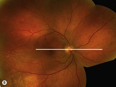
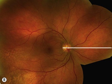
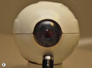
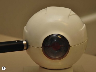
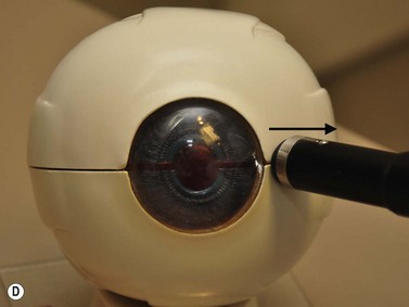
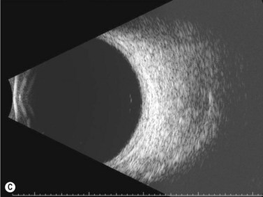
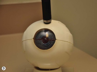
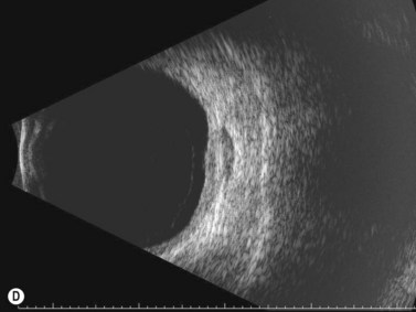
The longitudinal scan is obtained by placing the probe marker in the direction of the clock hour to be imaged (Figure 3.4) See Clip 3.3. The transducer located within the probe moves perpendicular to the limbus, sweeping along the radial plane of the fundus located opposite the probe tip. The resulting image shows the fundus along a specific clock hour. The fundus anterior to the equator is located at the top of the B-scan display, the fundus posterior to the equator is imaged centrally and the optic nerve is located at the bottom of the display. In this manner, the longitudinal scan shows the anterior to posterior extent of posterior segment pathology. The longitudinal scan does not usually require the examiner to actively rotate the probe. However, if the desired area to be examined is in the periphery, it can be helpful to place the probe tip closer to the fornix resulting in an image that demonstrates the peripheral fundus at the top of the display with the optic nerve at the far bottom of the display, or completely absent from the display. The longitudinal scans are labeled according to the clock hour imaged anterior to posterior. If the probe is placed at 9 o’clock with the marker towards the pupil, the transducer sweeps along the 3 o’clock plane (Figure 3.5). The resulting image is labeled as a longitudinal scan of 3 o’clock, or L3.
Longitudinal scan is the best orientation to evaluate membranes for insertion into the optic disc or adjacent to the optic disc (Chapter 10). It is also essential in the localization of small fundus abnormalities such as a retinal tear or a focal tractional retinal detachment as well as for the evaluation of the macula described later in this chapter.
Transverse scan
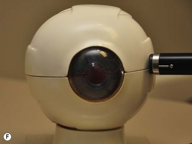
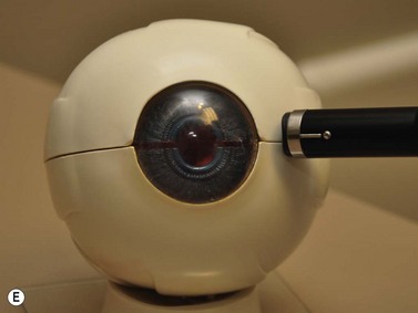
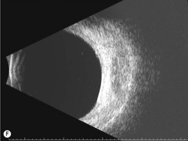
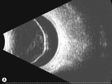
The transverse scan is obtained by placing the probe marker perpendicular to the clock hour to be imaged (Figure 3.6) See Clip 3.4. The transducer located within the probe moves parallel to the limbus, sweeping back and forth to the fundus located opposite the probe tip. The resulting image shows a circumferential section through many clock hours with the area of interest in the center of the displayed B-scan. For example, if the probe tip is placed on the limbus of the right eye at 6 o’clock with the marker facing towards 3 o’clock (perpendicular to 6 o’clock), the resulting image shows 3 o’clock at the top of the display, 6 o’clock in the middle and 9 o’clock at the bottom. The transverse scan is typically a dynamic exam. The probe is initially placed near the limbus to evaluate ocular pathology posterior to the equator. The probe is then slowly shifted more towards the fornix resulting in a scan near the equator. Continuing to move the probe away from the limbus results in transverse B-scan images that are anterior to the equator. The transverse scans are labeled according to the clock hour that is imaged in the middle of the scan. If the probe is placed in the right eye at 3 o’clock with the marker tip superiorly, the transducer sweeps from 12 o’clock to 6 o’clock with 9 o’clock in the center of the displayed image (Figure 3.7). The resulting image is labeled as transverse scan of 9 o’clock, or T9.
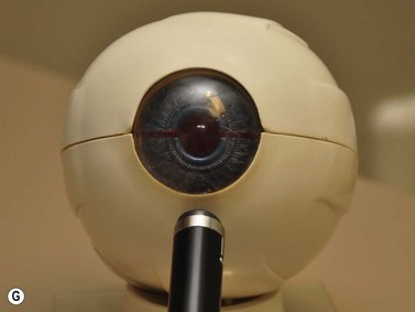
The transverse scan shows the lateral extent of posterior segment pathology and is essential in the evaluation of retinal detachments (Chapter 10) and the circumferential extent of ocular masses (Chapter 11).
B-scan examination methods
Five scan screening
The most common indication for B-scan is the evaluation of the posterior segment in the presence of opaque media. The goal is to create a three-dimensional mental image of the globe from many two-dimensional B-scan images. By performing four transverse B-scans and one longitudinal B-scan, at both high and low to medium gains, the entire posterior segment can be well imaged (Figure 3.8) See Clip 3.5. Additional B-scan orientations may be necessary to further view and document specific areas of interest. However, performing these five basic B-scans properly will ensure that most significant posterior segment pathology will not be missed.
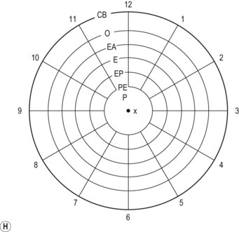
The superior portion of the globe is examined first by placing the probe tip on the conjunctiva near the limbus at 6 o’clock with the marker nasally (Figure 3.9). The resulting B-scan image is a transverse scan of 12 o’clock posterior to the equator (T12, PE). The ultrasonographer then slowly shifts the probe inferiorly towards the fornix without changing the direction of the probe marker. The sound beams will shift from an examination of the fundus posterior to the equator to the fundus near the equator (T12, E) and finally to the fundus anterior to the equator (T12, AE). In this dynamic manner the entire superior portion of the eye is imaged. The inferior portion of the eye is imaged next by placing the probe tip on the conjunctiva near the limbus at 12 o’clock with the marker still nasally and again shifting the probe superiorly towards the fornix. The resulting B-scan image is a transverse scan of 6 o’clock posterior to the equator. Again, the ultrasonographer shifts the probe towards the fornix to scan the inferior portion of the globe. The nasal and temporal portions of the globe are likewise imaged with the probe tip placed across from the portion of the globe of interest and movement of the probe from the limbus towards the fornix. However, the probe marker is turned superiorly. The resulting B-scans are the transverse B-scan of 9 o’clock and the transverse B-scan of 3 o’clock.
Detailed B-scan examination
Five B-scan screening indicated above will provide the ultrasonographer with an overview of the entire posterior segment. A more detailed examination will ensure the detection of subtler posterior segment pathology. See Clip 3.6 Longitudinal scans of the superior, inferior and nasal planes will help in the delineation of membranes adherent near the disk, thickening of the peripapillary fundus and lesions of the peripheral fundus near the ora serrata. Additionally, axial vertical and axial horizontal scans aid in the evaluation of optic disc irregularities, the retrobulbar optic nerve and Tenon’s space. Adjusting the gain setting during all B-scan examinations is essential. Vitreous opacities are best detected at a high gain, the retina and choroid at a medium gain and the sclera and orbital tissue at a low gain setting (Table 3.1).
| Tissue | Decibel value (dB) | Gain setting |
|---|---|---|
| Vitreous | 75–100 | High |
| Retina/choroid | 55–75 | Medium |
| Sclera/orbit | 35–55 | Low |
Diagnostic A-scan
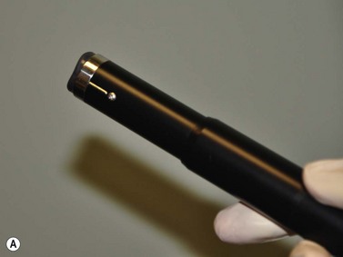
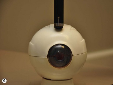
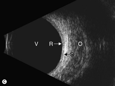
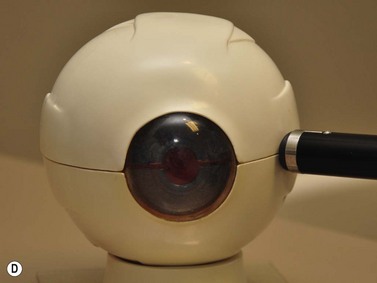
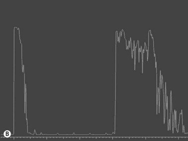
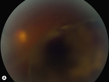
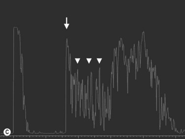
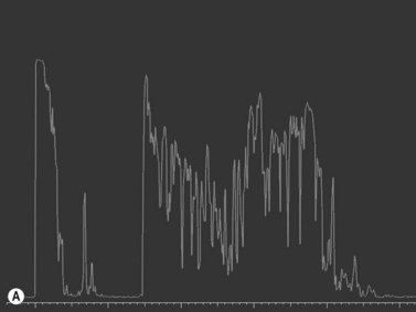
Diagnostic A-scan is performed when a thorough B-scan examination reveals an intraocular or orbital lesion (Figure 3.10). The A-scan probe is placed on the conjunctiva 180° across from the lesion while the patient gazes in the direction of the lesion. For a lesion located at 12 o’clock posterior to the equator, the probe is placed near the limbus at 6 o’clock and shifted slightly upward until the sound beam is perpendicular to the lesion. The resulting A-scan shows a tall scleral spike at the far left of the display, a horizontal line at the baseline through the center of the display corresponding to the vitreous space, several closely spaced tall spikes representing the retina, choroid, and sclera, and at the right of the display, several spikes of variable height corresponding to fatty orbital tissue (Figure 3.11).
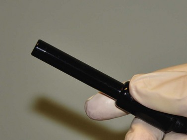
Figure 3.10 Diagnostic A-scan probe.
Reproduced with permission from Ellex Innovative Imaging, Minneapolis, MN, USA.
Differentiation of ocular lesions
Systematic and reproducible examination methods utilizing a combination of contact B-scan and diagnostic A-scan methods using topographic, quantitative, and kinetic ultrasonographic techniques are essential in accurately identifying ocular pathology (Table 3.2).
Table 3.2 Diagnostic features for assessing intraocular lesions.
| Topographic | Quantitative | Kinetic |
|---|---|---|
| Location | Reflectivity | Mobility |
| Shape | Internal structure | Vascularity |
| Extent | Sound attenuation | Convection movement |
Topographic ultrasonography
After a lesion is detected during a basic B-scan screening, topographic evaluation is initiated to determine location, shape and extent of the lesion. A transverse scan of the lesion should be performed first. See Clip 3.7 The B-scan probe tip is placed on the conjunctiva near the limbus 180° opposite the area of interest. For example, if the lesion is at 10 o’clock posterior to the equator, the probe tip is placed at 4 o’clock with the marker facing upward. The B-scan probe is then shifted peripherally towards the fornix to sweep through the lesion from posterior to anterior. The resulting B-scan displays the lateral extent of the lesion and the gross shape. When evaluating a solid intraocular mass lesion, the sweeping motion through the lesion is paramount in importance in order to determine the maximal height and lateral basal dimension of the lesion (Figure 3.12).11,12
 See Clip 3.8. For a lesion at 10 o’clock, the probe marker remains at 4 o’clock, but the marker is turned towards the clock hour of interest, perpendicular to the limbus. The resulting B-scan displays the anterior to posterior extent of the lesion and the gross shape. The probe is not shifted dramatically as required during the transverse scan. However, when delineating the height and anteroposterior basal dimension of a solid intraocular lesion, subtle shifts around the clock hour of interest will aid in the identification of the maximal dimensions.
The compilation of these various B-scan images allows the examiner to create a three-dimensional concept of the lesion’s location, shape and extent. These same B-scan techniques can also be used to determine the topographic features of a retinal detachment (Figure 3.13). Longitudinal B-scans will display a rope-like elevated membrane that inserts into the optic disc (Chapter 10).
Quantitative ultrasonography
After the topographic features of a lesion are evaluated, quantitative ultrasonography utilizing diagnostic A-scan can determine reflectivity, internal structure and sound attenuation. Reflectivity can help delineate many different intraocular lesions such as opacities, foreign bodies, membranes, bands, and mass lesions. Reflectivity is graded by the height of the spike on A-scan (Table 3.3). The tissue sensitivity gain setting is used to compare the height of a lesion’s spikes compared with a zero baseline and a 100% spike of retina and all tissues equal or higher in density (Chapter 2). Reflectivity can only be accurately determined when the A-scan probe is calibrated for tissue sensitivity and the sound beam is directed perpendicular to the lesion being evaluated (Figure 3.14). Judging the reflectivity from contact B-scan signal intensity is only an estimate of reflectivity and should not be relied upon for diagnostic purposes. Contact B-scan displays are not standardized and vary with resolution, gray scale, and dynamic range.
| Grade | A-scan spike height (%) |
|---|---|
| Low | 0–33 |
| Medium | 34–66 |
| High | 67–100 |
After reflectivity is determined, intraocular mass lesions can be further differentiated by quantitative ultrasonography by determining the internal structure. The internal structure is correlated with the histologic composition of a mass lesion.15 A homogeneous cell architecture within a lesion results in little variation in the height and length of the spikes on A-scan, whereas a heterogeneous cell architecture results in marked variation (Chapter 11).
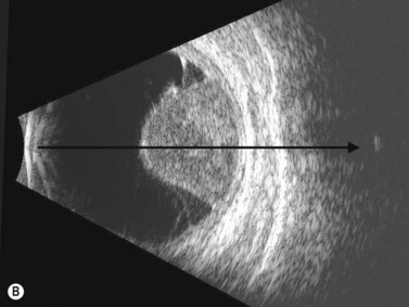
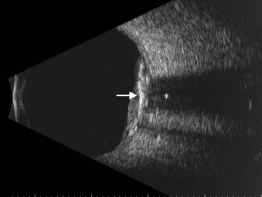
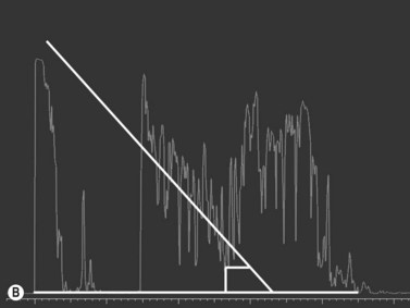
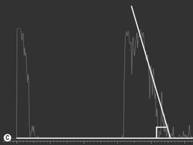
Sound attenuation or acoustic shadowing is the last component of quantitative ultrasonography. It refers to the diminished or extinguished echo pattern resulting from a strongly reflective or attenuating structure (Figure 3.15). Calcification of lesions, foreign bodies and bones are among the structures that cause sound attenuation. Sound attenuation is detected on both contact B-scan and diagnostic A-scan and is delineated by a marked, progressive decrease in the strength of the echoes within or behind a lesion. On B-scan, this results in reduction of the brightness of echoes or the complete absence of echoes termed as shadowing. On A-scan, progressive decrease in the height of the spikes can be depicted as an angular measurement (angle kappa).4 Angle kappa is proportional to the extent of sound attenuation, greater the attenuation of sound, greater the angle kappa (Figure 3.16).
Kinetic ultrasonography
Mobility
The mobility of a lesion is determined by movement of a membrane or opacity following a change in gaze or body positioning and is best examined with B-scan See Clip 3.9. Depending on the membrane of interest the appropriate transverse, longitudinal or axial B-scan is performed. The probe is held stationary with the membrane of interest centered on the B-scan display. The patient is then instructed to move their eyes quickly away from their fixation point and then back while the examiner continuously monitors the membrane and area of interest. Posterior vitreous detachments, retinal detachment, and choroidal detachments all exhibit distinctive patterns of mobility (Chapter 10).
Vascularity
Vascularity is the detection of fast, low-amplitude flickering consistent with blood flow within an intraocular solid lesion. It can be detected on both B-scan and A-scan. In both scans, the probe and patient’s gaze are held stationary while the internal echo flickering is observed over time. Vascularity is graded mild, moderate, or marked, corresponding to the intensity of the echo flickering See Clip 3.10. Color Doppler imaging and contrast agents are specifically designed to image/ detect the blood flow within the lesions (Chapter 5).
 See Clip 3.11 Convection movement is most commonly seen in eyes with long-standing vitreous hemorrhage that has settled beneath a tight funnel-shaped retinal detachment. Specific attention to this minor movement can greatly aid in the differentiation of settled debris and can help rule out intraocular solid mass lesions.
1 Ossoinig KC. Quantitative echography-the basis of tissue differentiation. J Clin Ultrasound. 1974;2(1):33-46.
2 Byrne SF. Standardized echography. Part I: A-scan examination procedures. Int Ophthalmol Clin. 1979;19(4):267-281.
3 Fisher YL. Contact B-scan ultrasonography: a practical approach. Int Ophthalmol Clin. 1979;19(4):103-125.
4 Ossoinig KC. Standardized echography: basic principles, clinical applications, and results. Int Ophthalmol Clin. 1979;19(4):127-210.
5 Ossoinig KC, Byrne SF, Weyer NJ. Standardized echography. Part II: Performance of standardized echography by the technician. Int Ophthalmol Clin. 1979;19(4):283-285.
6 Byrne SF. Standardized echography in the differentiation of orbital lesions. Surv Ophthalmol. 1984;29(3):226-228.
7 Farah ME, Byrne SF, Hughes JR. Standardized echography in uveal melanomas with scleral or extraocular extension. Arch Ophthalmol. 1984;102(10):1482-1485.
8 Byrne SF. Standardized echography of the eye and orbit. Neuroradiology. 1986;28(5–6):618-640.
9 DiBernardo C, Blodi B, Byrne SF. Echographic evaluation of retinal tears in patients with spontaneous vitreous hemorrhage. Arch Ophthalmol. 1992;110(4):511-514.
10 Collaborative Ocular Melanoma Study GroupBoldt HC, Byrne SF, et al. Baseline echographic characteristics of tumors in eyes of patients enrolled in the Collaborative Ocular Melanoma Study: COMS report no. 29. Ophthalmology. 2008;115(8):1390-1397.
11 Echography (Ultrasound) Procedures for the Collaborative Ocular Melanoma Study (COMS), Report no. 12, Part II. J Ophthal Nursing Technol. 1999;18(5):219-232.
12 Echography (Ultrasound) Procedures for the Collaborative Ocular Melanoma Study (COMS), Report no. 12, Part I. J Ophthal Nursing Technol. 1999;18(4):143-149.
13 Byrne SF, Marsh MJ, Boldt HC, et al. Consistency of observations from echograms made centrally in the Collaborative Ocular Melanoma Study COMS Report No. 13. Ophthal Epidemiol. 2002;9(1):11-27.
14 Bryne S, Green R. Ultrasound of the Eye and Orbit, 2nd ed. St. Louis: Mosby; 2002.
15 Green R, Byrne S. Diagnostic ophthalmic ultrasound. In: Ryan S, editor. Retina. 3rd ed. St. Louis: Mosby; 2001:240.