10 Chest X-Ray Interpretation
Pearls
• The chest radiograph must be used in conjunction with careful, clinical examination of the patient.
• Nurses should develop a systematic method of reviewing chest radiographs and use that format for examining every film.
• Loss of the cardiac silhouette indicates lung opacification (e.g., pneumonia, atelectasis).
• Remember that free air shifts or rises to superior portions of the chest, whereas free fluid tends to shift or fall to dependent (inferior) portions of the chest.
• Atelectasis represents a volume loss; therefore, structures are often shifted toward the area of atelectasis.
• Pneumothorax and hemothorax are conditions that represent a volume gain; therefore, structures are often shifted away from the area of pneumothorax or hemothorax.
• Because x-rays, CT scans, and fluoroscopy all use ionizing radiation, they should be used judiciously and with a specific indication or clinical question to be answered. (For more information, refer to the Image Gently campaign, available at: http://www.pedrad.org/associations/5364/ig/.)
Introduction
This chapter presents a systematic approach to interpretation of the radiograph and highlights the important factors that the nurse evaluates with this approach. This chapter will not discuss treatment of the problems identified on the radiograph. Evaluation of a chest radiograph may appear to be simple, but is in fact a complex task requiring careful observation, sound understanding of chest anatomy, and knowledge of the principles of physiology and pathology. The value of chest radiographs for critically ill pediatric patients is based on the diagnostic efficacy (the influence of a test result on diagnosis) and therapeutic efficacy (the effect of a test result on clinical management).2 A systematic approach to the review of a chest radiograph will help prevent errors in interpretation and diagnosis.
Definitions
X-rays are a form of short wavelength radiant energy. Images are produced when an x-ray beam is directed through an object to a film cassette. The image produced on the film is determined by the composition, or density, of the object through which the beam passes. The thickness of components of the body and structures in the body vary in their radiodensity, or ability to block or absorb the x-ray beam. To begin the interpretation of a radiograph, the nurse must be able to recognize the different densities that are produced on a chest radiograph and be aware of terms used to describe these differing densities and their radiographic appearances (Box 10-1). This will help differentiate between normal and abnormal findings on the radiograph.
Box 10-1 Glossary of Terms
• Density: Whiteness or any area of whiteness on an image
• Lucency: Blackness or any area of blackness on an image
• Shadow: Anything visible on an image; any specific density or lucency
• Edge: Any visible demarcation between structures of differing density; sharpest edges are created when there is density on one side and a lucency on the other
• Silhouette: Synonym for edge; the loss of an edge constitutes the silhouette sign
• Line: Thin density with lucency on both sides or a thin lucency with density on both sides
If the object is extremely dense, it will block or absorb a significant portion of the beam and prevent it from reaching and reacting with the film; this creates a gray or white shadow on the film. The more x-ray beam an object blocks or absorbs the more radiopaque or radiodense that object is. An object that is not very dense does not block or absorb much of the x-ray beam; it is radiolucent.19 When the beam passes through such an object, most of the beam reacts with the film, and the resultant image on the film will have a dark gray or black appearance.
Most complex objects are not of uniform density; they contain a variety of substances of varying densities, which produce shadows on a radiograph. There are four major categories of radiographic densities that appear on a radiograph; in order of decreasing density these are metal or bone, water, fat, and gas (or air).3 Metal is extremely dense, and it is the most radiopaque of materials. Pure metals block or absorb the entire x-ray beam and produce a bright white shadow on the radiograph. Because bones contain a large amount of calcium, they are nearly as dense and radiopaque as metal and also produce white images on the radiograph. Water and other fluids are fairly radiodense; they block a significant amount of the x-ray beam and have a gray appearance. Body tissues or cavities containing water or fluid (such as the heart) will produce a very light or white image on the radiograph. However, because water and fluids are not as dense as bones, bones and metals will still create whiter (more opaque) images than water. Because fat (including muscle) is not as dense as water, it does not block as much of the x-ray beam and consequently is less radiopaque or more radiolucent than bone or fluid. As a result, the radiograph shadow that fat produces is less dense than that produced by bone or water. Fat is contained in subcutaneous tissue and in some muscle; the x-ray image produced by these fat-containing tissues will have a dark gray or charcoal appearance. Gas or air is the least dense of substances visible on the chest radiograph. Because gas does not absorb much of the x-ray beam, it is radiolucent and produces a black image. Gas or air density is normally seen in the lung fields and in the air-filled stomach. The ability to discern muscle, blood, internal organs, fat, and tissues requires the understanding of normal anatomy.5,7,16,17
All parts of the body contain one or more of the four densities—metal or bone, fluid, fat, or gas. The juxtaposition of body parts or chambers of differing densities will create contrasts on the radiograph. When objects of varying densities are in contact, their borders will be apparent because of the contrasts in their radiographic images, and the difference in their images creates an edge or silhouette.3 When structures are visible on a radiograph, it is easy to evaluate their size, shape, and position. When two objects with similar densities are in contact or in the same plane as the x-ray beam, no spectrum of density is seen; therefore, there is no visible border between the objects on the radiograph.17 This finding may be normal based on normal anatomy. The silhouette sign describes the loss of a normal interface or silhouette, which is suggestive of abnormal tissues densities, often indicating a pathologic condition.6,16 This observation of abnormal density or silhouette sign can often confirm a diagnosis of inappropriate tissue, fluid, or air accumulation. The silhouette sign is commonly applied to the heart, mediastinum, chest wall, and diaphragm.
An x-ray film creates a two-dimensional image of three-dimensional objects as it compresses the image into one plane. As a result, the depth of structures often cannot be appreciated by evaluation of only one radiograph view. Many times, studies must be taken from two or more views so that the images can be compared to better evaluate the relative position of objects.14 Healthcare providers are aware that it is impossible to confirm correct placement of a tracheal tube from an anteroposterior (AP) or a posteroanterior (PA) x-ray alone, because such a film compresses the anterior-posterior dimension. The AP film can be used to evaluate depth of insertion and placement in or displacement from the midline. Only on the lateral view of the chest will it be possible to correctly evaluate the position of the tracheal tube relative to the trachea and esophagus.
An AP chest film is the view most frequently obtained in the critical care unit because it can be taken with a portable x-ray machine. When an AP view is obtained, the film cassette is placed under or behind the child and the child faces the x-ray tube. The child optimally should be in a sitting position; however, if there is difficulty in positioning the child because of acute illness or general immobility, the child is positioned supine. The x-ray beam is then directed from in front of the child through the child and to the film. As a result, the front of the child (anterior aspect) is nearest the x-ray tube when the film is taken. The AP film tends to magnify anterior chest structures, including the heart, because of the divergence of the x-ray beam; this makes it difficult to compare heart size in an AP versus a PA film. Heart size is most magnified in an AP supine film because of horizontal elongation of the ribs, higher placement of the diaphragm, and the impression of decreased lung volume.17
Whenever heart size is evaluated on chest radiographs, it is important to know whether the film was taken with a PA or an AP approach, although the difference is not as significant in infants and small children as it is in older children and adults.19 Changes in heart size, or in the size of any organ, can best be appreciated by comparing two images obtained using the same approach. Characteristically, chest films obtained in the radiology department under controlled conditions are clearer and of better quality than those obtained with a portable machine. Therefore, the films should be obtained in the radiology department whenever practical.
When PA or AP chest films are obtained, evaluation of lateral relationships of structures is possible, but assessment of AP relationships is not possible because of the compression of the image onto a single plane. If a determination of depth is necessary or if localization of a density is required, a lateral film is taken. Lateral chest films are usually obtained as part of a complete radiographic study of the heart and lungs. To obtain a lateral film, the patient is upright, the film cassette is placed on one side of the patient—typically the patient’s left side—and the beam is directed from the other side of the patient. The lateral film is labeled according to the side of the patient that is nearest the x-ray tube. If the patient’s left side is against the film cassette and the right side is nearest the X-ray tube, the resultant film is a right lateral film. Conversely, if the patient’s right side is nearest the film cassette and left side is nearest the x-ray tube, the film is a left lateral film.22
Lateral views allow evaluation of the AP relationships of body structures, but they do not allow determination of their lateral relationships. Therefore, the comparison and evaluation of both a PA and a lateral film provide much more information than either film does separately. An additional advantage of obtaining radiographs in two views is that thin structures (such as fissures) may be visible on only one film if the x-ray beam strikes the structure parallel to its long axis.9,24 When films of the same object are obtained using two different views, there is a greater chance that small structures will be apparent on one of the views.
A lateral decubitus view is obtained with the patient lying on one side or the other. The film cassette is placed at the patient’s back, and the x-ray beam is then aimed horizontally or parallel to the floor.9 A lateral decubitus view can be obtained in the critical care unit, and it is often helpful in determining the presence of air-fluid levels in the chest, such as those be seen when a lung abscess or pleural effusion is present. Positioning has a significant influence on the appearance of air, fluid, and blood vessels within the chest.
Interpretation of film technique
Patient Position and View
The evaluation of a chest radiograph requires knowledge of the exposure conditions of the film, the angle of the x-ray beam, and the alignment and position of the patient. If the x-ray tube is positioned close to the film and the patient, the x-ray image of the patient will be magnified. Conversely, if the x-ray tube is farther away from the film and the patient, the image of the patient will be smaller but sharper. The x-ray tube should be positioned so that the x-ray beam is exactly perpendicular to the plane of the film. If the patient is positioned properly, the x-ray beam will be perpendicular to the horizontal or vertical axis of the patient. If the x-ray beam or patient is slanted, and not perpendicular, a lordotic (oblique) view will be obtained and will show the body or chest at an angle. An oblique view is undesirable if it is obtained unintentionally, because structures farthest from the beam will be shortened while those closest to the beam will be enlarged.22 The child’s nurse should assist the radiology technologist in ensuring that the child is not rotated during exposure of the image. This can reduce the need for additional radiographs, with the associated increase in radiation to the child.
In a lordotic film, the clavicles are projected higher than normal and may be seen to lie above the lung apices, and the ribs appear more horizontal. In addition, it may cause hazy opacification at the lung bases as a result of overlapping soft tissues with magnification of the heart and mediastinum. If the apices of the lungs are not visible above the clavicles on an AP or a PA chest film, a lordotic view has been obtained, and this must be considered when evaluation of lung size and chest expansion is made.17
The alignment and the position of the patient at the time the film is taken also must be considered (Fig. 10-1). To determine whether a patient was positioned appropriately during the radiograph exposure, several structures should be evaluated. This evaluation includes the position of the trachea, curvature of the spine, position of the clavicles, length and symmetry of the ribs, and cardiac landmarks. If the patient is positioned straight and not rotated on the image, the trachea should project in the midline within the upper third of the chest. The spine should be straight with the intervertebral bodies outlined as separate from the disc spaces. With good alignment, the clavicles are of equal size and length. The medial ends of the clavicles should be equidistant from the thoracic spinous processes; they are normally projected over the lung apices and overlap the anterior first ribs. If the clavicles both appear horizontal and of equal size and length, a true AP or PA view was obtained.14 If, on the other hand, one clavicle appears to be smaller than the other (because it was farther away from the x-ray tube at the time the film was taken), or if one clavicle is at a different angle than the other, the patient was probably rotated, and an oblique view of chest structures appears on the radiograph, creating the appearance that one side of the chest image (and one clavicle) is larger than the other. As noted previously, if the apices of the lungs are not visible above the clavicles on an AP or a PA chest film, a lordotic view has been obtained.17
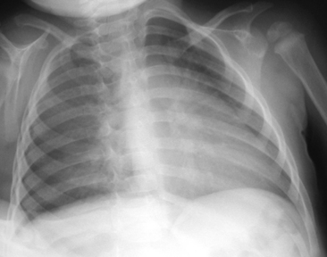
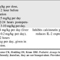
Fig. 10-1 In this chest radiograph the child is rotated to the left. Compared with Fig. 10-2, A, which demonstrates evidence of proper positioning, in this film the proximal ends of the clavicles are not symmetrical in appearance. The patient’s left clavicle appears larger. The ribs on the patient’s right side are more curved posteriorly, and ribs in the patient’s left chest are more elongated with greater visualization of the anterior ribs. The cardiac silhouette is more prominent in the left chest with a normal cardiothoracic ratio, but the heart shape is altered by the rotated view.
Air tends to rise to the highest point within the chest cavity. As a result, in an upright view, free pleural air (such as a pneumothorax) will rise toward the apex of the lung. On a supine film, the highest point in the chest lies adjacent to the heart and mediastinum. When the child is supine for an AP film, free pleural air usually is seen along the diaphragm or the sides of the lung fields. Free air will typically cause increased lucency at these points, often with no lung edges or lung vascular markings visible.9,14 If free air is suggested on a supine view, it can be confirmed by a decubitus view. When the child is positioned on the dependent side opposite to the free air, any air in the pleural cavity will rise to lie along the lateral chest wall.17
Film Technique
When the exposure of the film is not correct, the change in exposure will affect the entire film appearance. If the chest radiograph is underpenetrated (underexposed), all the structures on the radiograph will appear lighter in appearance or diffusely opaque (i.e., too white). The resulting images are difficult to interpret, preventing a detailed view of the mediastinal, retrocardiac, and spinal anatomy. Pathologic findings in the left lower lobe can be missed easily.27 In addition, pulmonary vascular markings will appear to be more prominent, with less distinct borders; thus, they may be mistakenly interpreted to be increased or hazy resulting from interstitial edema. If a film is overpenetrated (overexposed), all the images on the radiograph will be darker or diffusely lucent. The lungs will appear blacker than usual. Overpenetration can obliterate shadows and can make pulmonary vascular markings appear to be reduced.16
If the film is obtained during expiration, the heart will appear larger and less well defined. The lung fields will appear to be hazier and the pulmonary vascular markings more prominent. Hypoinflation of the lung fields can lead to misinterpretation of the images and misdiagnosis of a basilar pneumonia or cardiomegaly. Furthermore, if maximal inspiration is not present, the lungs can appear more congested and the trachea will appear to buckle to the right.21,24 Figure 10-2 illustrates these differences with two views obtained from a normal child during inspiration and expiration.
The child must not move while the film is taken because motion can blur cardiothoracic structures. Blurring of the diaphragm can mimic the appearance of pulmonary infiltrates.19 If the nurse or radiology technologist suspects that the child moved when the film was taken, this should be noted for consideration when the film is interpreted. If excessive motion artifact is present, another film should be obtained.
Interpretation of chest radiograph
Systematic Approach
When an organized systematic approach is used to examine the radiographic image, the nurse will be less likely to overlook significant abnormalities. It is often advisable to initially ignore the most striking or obvious features of a radiograph to avoid overlooking other equally important features. Table 10-1 provides one method of organizing the review of a chest film. Because there are many correct sequences that can be used to interpret the film, the nurse must develop an individual, comfortable style. The most important thing about any approach is that it must include all aspects of the film review. Once a healthcare provider develops a systematic and comprehensive approach to reviewing a film, the provider should use this method every time to ensure that nothing is missed during the review.
Table 10-1 An Organized Approach to Chest Radiograph Examination
| Focus of Examination | Aspects of Examination |
| Technique | 1. Check alignment and position (check clavicles) |
| 2. Check degree of inspiration (9 to10 ribs should be visible with full inspiration) | |
| 3. Check penetration (vertebral bodies should be easily visualized) | |
| Soft tissues of chest and neck | 1. Check for subcutaneous emphysema |
| 2. Examine extrathoracic structures | |
| Bony thorax and intercostal spaces | 1. Examine clavicles, scapula, ribs, humeri, and cervical and thoracic vertebrae |
| 2. Check for fractures | |
| 3. Evaluate width of intercostal spaces (should be equal) | |
| Diaphragm and area below diaphragm | 1. Note clarity of diaphragm and location (check for elevation) |
| 2. Check for location of gastric bubble (normal: patient’s left) | |
| Pleura and Costophrenic angles | 1. Check for presence of fluid or air between pleural layers (look between bony thorax and lung) |
| 2. Costophrenic angle should be sharp | |
| Mediastinum | 1. Borders should be sharp |
| 2. Check for lateral shift | |
| Trachea | 1. Should be straight (may buckle to left on expiratory film if right aortic arch is present) |
| 2. Check for narrowing or deviation | |
| Heart and great vessels | 1. Borders of heart and aorta should be distinct |
| 2. Obliteration of heart borders is called silhouette sign (see Table 10-2) | |
| 3. Measure cardiothoracic ratio—normally approximately 0.5 for children and adults (half the width of the chest) | |
| Lung fields | 1. Compare right with left |
| 2. Note presence and location of any opacification; describe it | |
| 3. Look for air-fluid levels | |
| Hili and pulmonary vascularity | 1. Pulmonary vascularity is most prominent at hili |
| 2. Peripheral pulmonary vascular markings usually are visible in proximal two thirds of lung fields (note if markings are increased or decreased) | |
| 3. Prominent but hazy pulmonary vascular markings may result from pulmonary edema or pulmonary venous congestion | |
| Check location and continuity of all tubes, catheters and wires | 1. Note position of head when evaluating endotracheal tube position |
| 2. Tip of endotracheal tube should be at level of third rib (1-2 cm above carina) | |
| Compare with previous films |
Soft Tissues and Bony Thorax
Examine the soft tissues of the chest wall for evidence of subcutaneous emphysema (air density between the skin and bony thorax), which can result from an air leak around the chest tube or from a penetrating chest wound. In addition, tissue swelling can indicate the presence of an injury. Check the soft tissues of the neck for subcutaneous emphysema. In addition, if the child is intubated, note the position of the child’s head, because flexion or extension of the head can change the position of the tip of the endotracheal (ET) tube.15
Examine the bony thorax and the shape of the chest. Infants and young children normally have round chests with a horizontal orientation of their ribs (see Fig. 10-2). However, older children and adults have chests that are wider than they are deep, and their ribs angle downward from back to front. A round chest in an older child or adult is abnormal and may be the result of chronic respiratory disease with air trapping. As discussed, nine or ten ribs should appear above the dome of the diaphragm if a good inspiratory film has been obtained.
Check the continuity of vertebrae, ribs, scapulas, and clavicles for fractures and bony destruction. The ribs and intercostal spaces should be symmetrical. A fracture often will create a dark line in the bone because of separation of the bone fragments (Fig. 10-3). The vertebral bodies, particularly the cervical vertebrae, should be checked closely for fractures if the child has been admitted following trauma. The presence of multiple rib fractures, especially both posterior and anterior, and in various stages of healing is pathognomonic (positive predictive value of 95% or higher in children 3 years of age and younger) for child abuse.4 Healing fractures often have an enlarged area consisting of cartilage and woven bone creating a callus. Rib notching, or erosion of the underside of ribs caused by enlargement of the intercostal arteries, can be seen in older children with coarctation of the aorta, because the intercostal arteries become enlarged to carry collateral circulation around the area of coarctation into the descending aorta. Abnormalities of the ribs may be noted if the child has had surgery to alter the size or shape of the rib cage. Splinting can produce narrowing of the intercostal spaces on one side of the chest.
Evaluate the width of the intercostal spaces. Following a thoracotomy, muscle spasm or sutures can reduce the width of the intercostal space at and near the site of surgery. In addition, significant atelectasis can cause narrowing of the intercostal spaces on the involved side and widening of the spaces on the noninvolved side.9,14 Hyperinflation, associated with air trapping, will cause widening of the intercostal spaces bilaterally.
Diaphragm and Abdomen
Examine the position and appearance of the diaphragms, including the shape, height, and angles. The patient’s right hemidiaphragm is usually approximately 1 to 3 cm higher than the left hemidiaphragm because the liver lies under the right diaphragm. The diaphragms should appear smooth and domed, with sharply defined costophrenic angles (the angle produced by the lateral downward curve of each hemidiaphragm at its periphery). Unilateral elevation of the diaphragm may be caused by diaphragm paralysis; this may be congenital in origin or result from chest trauma or injury to the phrenic nerve during thoracic surgery (Fig. 10-4). The elevation occurs during spontaneous inspiration, but will not occur during positive pressure inspiration. Atelectasis and abdominal organ distension are additional potential causes of unilateral elevation of the diaphragm. Bilateral elevation of the diaphragm may be observed in the child with hypoventilation, abdominal distension, ascites, intraabdominal mass, or obesity.
If the clear silhouette between the air density of the lungs and the tissue density of the diaphragm is obscured, it is usually caused by basilar atelectasis or accumulation of free pleural fluid along the diaphragm (Fig. 10-5). The accumulation of subpulmonic fluid can create an appearance similar to that produced by an elevated diaphragm if an AP film is taken with the patient upright. The free fluid will be readily apparent, however, when a lateral decubitus film is taken.
The diaphragm can appear to be unusually flat and depressed in any condition that increases the volume of the lung or the contents of the hemithorax. The patient’s diaphragm will be unilaterally flattened and displaced downward if the child has a significant unilateral (tension) pneumothorax or if the child has unilateral lung disease and hyperexpansion of one lung (see Fig. 10-4, noting the appearance of the child’s right hemidiaphragm).22
After evaluation of the diaphragm, examine the structures below the diaphragm. There is usually some air in the child’s stomach—in fact, the absence of gastric air in the neonate is one of the pathognomonic radiographic signs of esophageal atresia.20 The gastric bubble should appear under the patient’s left hemidiaphragm. If the gastric bubble is present under the patient’s right hemidiaphragm, situs inversus is present (i.e., the abdominal organs are transposed). The bedside nurse should be aware if the child has situs inversus, because this will affect subsequent assessments such as location for auscultation as part of the process of checking placement of the nasogastric tube or palpation of the liver for evidence of hepatomegaly. In addition, situs inversus can be associated with cardiac malpositions, congenital heart defects, or asplenia (see Chapter 8).13,23,24 Normally, there should be no free air in the peritoneal cavity although air is usually present in the child’s stomach, intestines, and colon.19
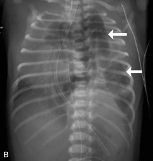
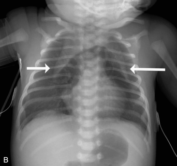
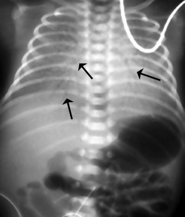
The newborn with diaphragmatic hernia may demonstrate severe respiratory distress. The chest radiograph reveals multiple abnormal air lucencies within the chest, usually the left hemithorax. This air is caused by the presence of loops of air-filled bowel in the chest (Fig. 10-6). The bowel compresses the lung on the involved side and shifts the mediastinum to the noninvolved (usually right) hemithorax, compressing that lung. Until the bowel fills with swallowed air, the newborn with a diaphragmatic hernia may be thought to have a mass in the left chest.
Pleura and Costophrenic Angles
The pleura consist of a double-layered serous membrane; the parietal pleura lines the inside of the thoracic cavity, and the visceral pleura adheres to the outside of the lung. The space between these two layers (the pleural cavity or space) is normally collapsed so that the two layers cast only a thin, white shadow on the radiograph.22 However, if fluid (hemothorax, effusion) or air (pneumothorax) accumulates in the pleural space, an air-fluid interface or a fluid density may be observed between the bony thorax and the lung. The pleura will cast a thicker white shadow on the radiograph if the pleura thickens as the result of pleural reaction (e.g., following surgery or other irritation). The fluid shadow created by pleural thickening or a loculated pleural effusion will not change when the patient changes position.
When examining the pleura, it is important to follow it and any visible pleural space around the entire margin of each lung. Because free pleural fluid tends to accumulate in dependent portions of the chest, fluid may be noted along the diaphragm in an upright film and behind the lungs in a supine film. On an upright film, small collections of fluid can obscure the costophrenic angle, and more significant collections of fluid tend to obscure the diaphragm and make it appear elevated (see Fig. 10-5, A).9,14
On a supine film, free pleural fluid may appear to opacify the lung fields, often making it difficult to distinguish from pulmonary congestion.9 In this case an upright or lateral decubitus film is usually obtained (see Fig. 10-5, B).
The lungs are divided into lobes by fissures; the right lung has three lobes and the left lung has two lobes. The oblique or major fissures, separating the upper from the lower lobes, are not usually seen on a chest radiograph because they face toward the x-ray beam on AP view. Fluid accumulation in the major fissure is best seen on a lateral film. The minor fissure in the right lung separates the right upper and right middle lobes, and it lies tangential to the beam in an AP view. Fluid can accumulate in the minor fissure; this fluid accumulation often can be observed on both AP and lateral films.9,21
A pneumothorax will produce an air-tissue interface in the pleural cavity because the pneumothorax contains only air with no pulmonary vascular markings, whereas the lung contains air, tissues, and vessels. The presence of a significant pneumothorax will cause partial or complete collapse of the adjacent (ipsilateral) lung. Note that free pleural air will accumulate in the highest portions of the chest so that the location of the air is influenced by the patient’s position when the X-ray is obtained. In an upright film, free pleural air is typically observed above the apex of the lung, whereas in a supine film the air may accumulate along the anterior and lateral aspects of the lung and along the diaphragm (Fig. 10-7).
The costophrenic angle is a sharp angle formed bilaterally from the downward curve of the lateral diaphragm seen on an AP (or a PA) film. The bases of the lower lobe of each lung dip into this recess. Obliteration or blunting of this angle can occur with accumulation of relatively small amounts of free pleural fluid. The angle also can be blunted if pleural reaction or thickening is present.22
Mediastinum and Trachea
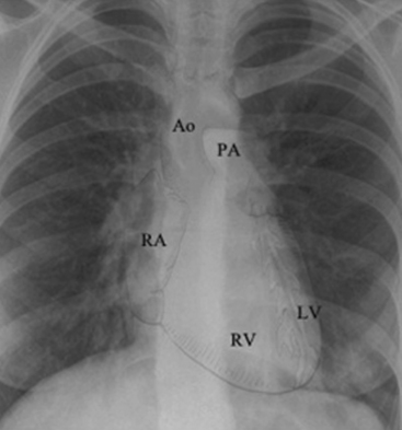
The mediastinum contains the trachea, the two main bronchi, the esophagus, the ascending aorta, the aortic arch (and major branches), the main pulmonary artery (and the proximal right and left pulmonary arteries), the major veins of the heart, the heart, and the thymus (Fig. 10-8). Because most of these structures contain fluid, the radiographic appearance of the mediastinum is that of a single fluid density between the lungs.
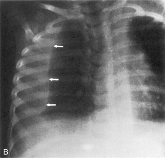
Children older than 6 years have mediastinal structures comparable to those of adults. The thymus shadow, seen in the upper third of the chest at the mediastinum, has bilateral lobes. The thymic silhouette blends almost imperceptibly with the cardiac silhouette, because it occupies contiguous space, giving the appearance of a widened mediastinum. It can produce a triangular shadow, resembling the sail of a boat (called the sail sign). The thymus is most often visualized on the chest radiograph from birth to 2 years of age, but may persist up to 5 years of age6,16,17,25 (Fig. 10-9).
The trachea should be straight, and often it is located slightly to the right of the patient’s midline. Because the trachea contains air, a dark vertical radiolucent column identifies its position within the mediastinum (see Fig. 10-2). The posterior portion of the aortic arch creates a knob or curve that usually is seen just to the left of the patient’s spine. If the aorta arches to the right instead of to the left, the aortic knob can be superimposed on the shadow of the patient’s spine on the AP projection, and the trachea is displaced to the patient’s left. The incidence of congenital heart disease is higher in patients with a right aortic arch, although a right aortic arch can be seen in otherwise healthy patients.11,21
The aortic knob and the trachea will be displaced if a mediastinal shift occurs. When significant atelectasis is present, the trachea and aortic knob usually are displaced toward the area of collapse, because of the volume loss associated with the atelectais.22 However, if a large pleural effusion or pneumothorax is present, the trachea and aortic knob typically will be displaced away from the involved lung and toward the unaffected side, because these problems represent volume gain in the chest (Fig. 10-10).
The trachea is identified by a straight vertical air density typically just to the right of the patient’s midline. As noted previously, it may appear to buckle to the right on an expiratory film, or it may be displaced toward an area of atelectasis or away from a pneumothorax or pneumomediastinum (see Fig. 10-10). The trachea bifurcates into the right and left mainstem bronchus at approximately the level of the patient’s fourth rib. The carina, a portion of the lowest tracheal ridge, is located at the bifurcation of the trachea and is used as a landmark in radiographic assessment of tracheal tube placement. In adults, the angle of branching of the left main bronchus is normally lower than the angle of branching of the right main bronchus. The right main bronchus typically branches off higher with a sharper angle. For this reason, aspirated substances frequently enter the right bronchial tree.21
The left hilum is normally higher than the right because the left side is elevated by the heart. Normal heart position extends approximately two thirds to the left of the midline in the chest. The center of the heart lies under the lower third of the sternum.10,18 If the child has dextrocardia or dextroversion, the heart will be located in the center of the chest or in the right chest, and additional congenital heart lesions are likely to be present.21,23 The cardiac shadow on the AP film is created largely by the shadow of the superior vena cava, the right atrium, the aortic knob, the main pulmonary artery, the left pulmonary artery, and the left ventricle.21 The right ventricle and left atrium normally do not contribute to the margin of the heart shadow in the AP or PA view.
Heart and Great Vessels
The size of the heart is quantified on AP or PA view by calculation of a ratio of the width of the heart to the width of the thorax, called the cardiothoracic ratio. To obtain the cardiothoracic ratio, the heart is measured between vertical lines drawn at its widest margins (from the center) on the right and left, and the chest is measured at the costophrenic angles on the inside of the rib cage (Fig. 10-11).
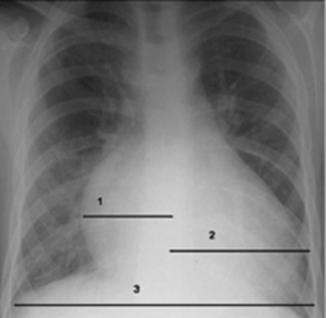
Beyond the newborn period, the heart’s width does not normally exceed half the width of the thorax. The cardiothoracic ratio in newborns is normally up to 0.55. In older infants and children up to 6 years of age, a ratio of 0.45 is normal. Between 6 and 12 years of age, a cardiothoracic ratio of up to 0.44 is normal.21 A convenient rule is that the cardiothoracic ratio in children is normally 0.5, plus or minus 5% to 6%, and it is typically larger in neonates and smaller in older children. An increase in the cardiothoracic ratio suggests the possibility of cardiomegaly. However, a poor inspiratory film and AP (compared with PA) chest radiographs will affect the accuracy of the cardiothoracic ratio.7,16,17 For practice, calculate the cardiothoracic ratio in Fig. 10-2, A. The ratio is 0.52.
Cardiac enlargement can increase the cardiothoracic ratio. Note that cardiac chamber hypertrophy may not alter heart size appreciably, because the cardiac shadow is determined by the outer border of the heart chambers and is not influenced by the thickness of chamber walls. Cardiomegaly that is apparent on the radiograph is caused by an increase in cardiac chamber volume; thus, it is most often a result of cardiac dilation (Fig. 10-12).14,21
Right atrial enlargement will often cause displacement of the right heart border toward the patient’s right side. The right atrial portion of the right heart margin also may appear to be more convex. Right ventricular enlargement can be difficult to discern from the AP film alone. When this ventricle enlarges, the rest of the heart is displaced posteriorly and cephalad (upward). Frequently, this enlargement increases the transverse diameter of the heart and pushes the cardiac apex outward and upward, like the upturned toe of a shoe or boot, although this is not an invariable radiologic finding.14,21 Right ventricular enlargement can be discerned better from a lateral chest film, because the enlarged anterior right ventricle will fill the retrosternal space and rest against the sternum. In small infants, it may be difficult to differentiate between the retrosternal thymus and the retrosternal right ventricle.14,21
Left atrial enlargement may be difficult to discern on a chest radiograph, because the left atrium normally does not form a distinct portion of the cardiac margin. With left atrial enlargement, the left heart border below the aortic knob may straighten or become convex instead of concave. In addition, the posterior enlargement of this chamber can elevate the left mainstem bronchus so that the angle of the tracheobronchial bifurcation is widened. A double density also may be observed in the center of the cardiac shadow14,21 (Fig. 10-13).
Left ventricular enlargement generally increases the transverse diameter of the heart and extends the left heart border toward the left chest wall. Commonly, left ventricular enlargement will displace the cardiac apex downward and outward so that it rests on the diaphragm.14,21
After cardiovascular surgery, the mediastinum and cardiac silhouette may be enlarged as the result of bleeding or fluid accumulation around the site of surgery. If the cardiac silhouette widens dramatically in the presence of tachycardia, signs of pulmonary and systemic venous congestion, and decreased systemic perfusion, cardiac tamponade may be present.22 However, it is important to note that the cardiac silhouette may remain small despite the presence of tamponade if the pericardial sac does not distend.
Cardiac enlargement often is seen when the child has congestive heart failure. Heart failure, often biventricular in children, can produce a global enlargement of all heart chambers.14 Pulmonary vascular markings also will be indistinct (see Fig. 10-13).
The great vessels may be enlarged or reduced in size as the result of congenital heart defects. If the child has a thoracic coarctation of the aorta, a characteristic E configuration of the aortic silhouette may be seen, which is caused by the coarctation. The presence of coarctation of the aorta, patent ductus arteriosus, or aortic valvular stenosis may cause the aortic knob to be more prominent than usual.11
Some congenital heart defects, such as severe tetralogy of Fallot or pulmonary atresia, are associated with a small main pulmonary artery. With a small main pulmonary artery, a concavity of the upper portion of the left heart border may be observed, because an extremely small main pulmonary artery will not produce the normal convexity below the aortic knob. This abnormal concavity can make the mediastinum appear to be narrow, because the upper heart shadow is created only by the aorta instead of by the pulmonary artery and aorta. Many children with tetralogy of Fallot or pulmonary atresia have a right aortic arch, so that the aortic knob is located to the right of the patient’s trachea. This condition will further decrease the fullness of the left heart border. If significant obstruction to pulmonary blood flow is present, pulmonary vascular markings may be diminished.11,14,21
The borders of the heart and great vessels should be sharp. Because the cardiac silhouette is created by the contrast between the fluid density of the heart and the air density of the lung, obliteration of the sharp border between the lung and heart is associated with an abnormality where areas of these organs are normally in contact. This loss of a normal silhouette on a radiograph is referred to as the silhouette sign.9,17 The silhouette sign helps determine the location of the abnormal finding within the chest. Obliteration of the heart border is typically caused by opacification (congestion or atelectasis) of portions of the lung that are in anatomic contact with the heart or great vessels. It also can occur as a result of pleural fluid accumulation, pneumonia, or a lung mass.
To determine the reason for the appearance of the silhouette sign, the nurse must know which areas of the lung are in direct contact with the heart or great vessels. These areas are summarized in Table 10-2. Obliteration of the margins of the upper portion of the right heart border and ascending aorta can occur as a result of opacification of the right upper lobe. Opacification of the right middle lobe can result in loss of most of the right side of the heart border. Because the right lower lobe is posterior and not in direct contact with the heart, opacification of the right lower lobe will overlap the heart border but will not obliterate it.
Table 10-2 Significance of the Silhouette Sign: Obliteration of Cardiac Silhouette by Lung Opacification
| Obliterated Heart Border or Structure | Opacified Lung Segment |
| Upper portion of the right heart border and ascending aorta | Right upper lobe |
| Most of the right heart border | Right middle lobe |
| Right diaphragm | Right lower lobe |
| Aortic knob (and upper left heart border) | Left upper lobe |
| Most of left heart border | Superior and/or inferior left lingula |
| Left diaphragm | Left lower lobe |
If the margin of the aortic knob is indistinct, it generally results from opacification of the left upper lobe. Atelectasis or pneumonia of the left lingula will obliterate most of the left side of the heart border. Because most of the left lower lobe is posterior and not in direct contact with the heart, left lower lobe opacification will overlap the heart but will not obliterate its silhouette.9
Lungs, Hili, and Pulmonary Vascularity
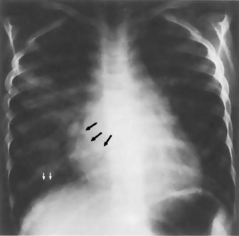
The air-filled peripheral bronchi normally are not visible on the chest radiograph. Visualization of a bronchus is called an air bronchogram. A bronchus is visible only if it is surrounded by an intrapulmonary structure of water or of fluid density. It can be seen as the result of pneumonia, atelectasis, pulmonary edema, consolidation, infarction, or certain chronic pulmonary lesions.9 In addition, an air bronchogram can be seen within the mediastinum in the radiographs of normal infants and young children, because portions of their lobar bronchi lie within the tissues of the mediastinum (Fig. 10-14). Although an air bronchogram is almost invariably associated with intrapulmonary disease in adults, it may be a normal finding in the mediastinum of infants and young children.9,21
The hili of the lungs contain the pulmonary artery and vein for each lung and the right and left main bronchi. Because the bronchi normally do not produce a radiographic shadow, the shadows of the right and left hili are produced by the right and left pulmonary arteries and veins and their major branches. In the majority of patients, the left hilum is slightly higher than the right hilum.8,9,16,22,24,26 The hili may be enlarged by congenital heart defects that produce increased pulmonary blood flow and pulmonary artery dilation, such as ventricular septal defect or patent ductus arteriosus. The hili also may be enlarged in the presence of pulmonary venous dilation associated with congestive heart failure or pulmonary venous obstruction. Often, both pulmonary arteries and veins are enlarged (e.g., when the child with a large ventricular septal defect develops congestive heart failure). Enlargement of the hili also may be caused by lymph node enlargement.
The hilum of a lung can be displaced toward an area of lung collapse or away from a significant pneumothorax or pleural effusion.9 This shift is best appreciated by comparing the film showing suspected displacement with a previous film.
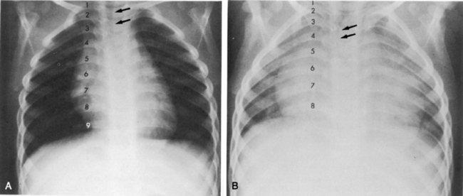
Pulmonary edema, pulmonary hemorrhage, overwhelming infection, aspiration pneumonitis, and pulmonary venous obstruction can cause perihilar opacities,14 making the lung hili more radiopaque and hazy in appearance (Fig. 10-15). The surrounding lung tissue may be more radiopaque with a reticular appearance caused by interstitial edema. Occasionally, the lung fields are radiolucent, creating a dark halo around the hazy opacity of the hili.
Pulmonary edema, infectious pneumonitis, and pulmonary venous obstruction often produce diffuse changes that are bilaterally symmetrical. Aspiration pneumonitis and partial pulmonary venous obstruction can produce unilateral or localized opacifications. Rarely, pulmonary edema can be segmental.14,21 Further evaluation of the pulmonary vascularity is made by examination of the peripheral pulmonary vascular markings.
When the newborn has pulmonary venous obstruction associated with left-sided heart failure or obstruction, or total anomalous pulmonary venous connection (TAPVC) below the diaphragm (or other forms of TAPVC with obstruction), and pulmonary venous pressure increases, redistribution of pulmonary blood flow often does not occur. Instead, lung fields become more radiopaque as a result of venous congestion, and the lung fields have a uniform “ground-glass” appearance caused by interstitial edema and pulmonary venous dilation.27
When pulmonary venous obstruction is present in the older infant or child and pulmonary venous pressure increases (e.g., caused by left heart failure or obstruction), blood flow in the lungs is redistributed. Normally, when the patient is upright, blood flow in the bases of the lungs is greater than flow to the apices. With an increase in pulmonary venous pressure, blood flow is redistributed and shifted to the upper portions of the lungs, causing a prominence of apical pulmonary venous markings.21 With progressive pulmonary venous congestion, interstitial edema develops, and the lung hili and all vascular markings begin to become hazy and indistinct. The hili may be particularly opaque.
Kerley-B lines may be seen with severe pulmonary venous congestion. These lines appear as thin, radiopaque, horizontal streaks in the lung bases that are thought to represent lymphatic channels in the interlobular septa of the lungs (see Fig. 10-13).21,24 If pulmonary venous pressure increases further, transudation of fluid into the tissue can occur. This transudation produces diffuse opacification of both lung fields. Air bronchograms may be visible (see Fig. 10-14).
When the child develops pulmonary hypertension with increased pulmonary vascular resistance, the hilar and proximal pulmonary vessels often appear to be prominent, but peripheral pulmonary vascular markings can be absent. This radiographic appearance of the pulmonary vessels is referred to as the pruned tree configuration.14,21 Because chest radiographs are not the chief method used to confirm or rule out the diagnosis of pulmonary hypertension, the observation of findings consistent with pulmonary hypertension should be used only to provide an index of suspicion. Many children with significant pulmonary hypertension have normal chest radiographs.
Occasionally, children with severe long-standing obstruction of pulmonary arterial blood flow (e.g., caused by uncorrected or palliated pulmonary atresia) develop prominent bronchial collateral vessels that proliferate, thus increasing the absolute amount of pulmonary blood flow. These vessels can be highly dense, but they often do not follow the normal branching pattern. These children are likely to have a normal or diminutive main pulmonary artery shadow and small right and left hili.14,21 When pulmonary artery blood flow is reduced, the lung fields appear to be abnormally radiolucent (or “empty”), because they do not contain the normal opacities produced by pulmonary vessels.
Common radiographic abnormalities
The term air space disease applies to the presence of abnormal (i.e., nonair) densities in the lung fields. These densities can be localized or diffuse and generally indicate the development of lung disease, atelectasis, or tumor or the accumulation of exudate, transudate, or blood in the lung.14 Often it may be difficult to differentiate between opacification produced by intrapulmonary (air space) disease and that produced by fluid accumulation in the pleural space. The following discussion includes identifying characteristics of each problem and clues to differentiating among them.
Atelectasis produces intrapulmonary opacification as the result of collapse of a portion of the lung tissue (Fig. 10-16). Atelectasis is usually seen as a diffuse increase in density with either a linear, angular, or streaked appearance in the affected area. Atelectasis is typically produced by intrinsic obstruction of an airway (caused by a mucous plug, exudate, or foreign body), extrinsic compression of the airway by another thoracic structure (e.g., enlarged lymph nodes, large heart, tumor), or significant hypoventilation. Because atelectasis represents loss of lung volume (i.e., lung collapse), other intrathoracic structures shift toward the area of atelectasis. The trachea, mediastinum, hilum, and any visible intrapulmonary septa can all shift toward the atelectatic area. If the upper lobe is involved, the loss of volume also elevates the hilum on the affected side. In addition, the hemidiaphragm on the involved side is elevated, and the intercostal spaces on that side become narrow. Air bronchograms may be present within the opacified area, and the visualized bronchi often are crowded together because of lung collapse. The uninvolved lung can become hyperinflated, producing a widening of the intercostal spaces on the nonatelectatic side and subsequent flattening of the hemidiaphragm.
Pleural fluid accumulation can result from pleural effusion, chylothorax, hemothorax, hydrothorax, empyema (a purulent pleural space infection), or a pleural reaction. The fluid will infiltrate the lung space and appear as a density on the radiograph. The infiltrative process typically is seen at the periphery of the lung and moves inward with a hazy, white appearance without air volume loss. Free pleural fluid characteristically assumes a dependent position so that in the upright chest film it generally accumulates along the diaphragm. With small amounts of fluid accumulation, the costophrenic angles are blunted; with increasing amounts of fluid accumulation, the diaphragm will appear to be elevated and fluid will accumulate laterally as well (see Fig. 10-5, A). On average, more than 150 m of fluid must be present for a pleural effusion to be detected on an upright film. Smaller amounts, greater than 75 mL, can be detected on a lateral decubitus view when the patient is positioned so the affected side is dependent (i.e., the affected side is down).25,26 Fluid also can accumulate in the fissures between lobes of the lung.
If the free pleural fluid continues to accumulate, the entire hemithorax can be filled; this produces complete opacification of that hemithorax, with compression of the underlying lung and flattening of the involved hemidiaphragm.14 The trachea, mediastinum, and hilum usually are shifted away from significant fluid accumulation, because it represents an increase in intrathoracic volume (unless concurrent atelectasis is present on the involved side). A lateral decubitus view is not indicated in this case, because there is no air interface to assist in further characterization of the fluid. Ultrasound examination, however, can be extremely helpful.
If the child is supine when the chest radiograph is taken, free pleural fluid will accumulate along the posterior surface of the chest, because it is dependent when the child is supine. This condition will produce a diffuse opacification within the involved thorax that may be difficult to differentiate from interstitial lung disease. An upright film or a lateral decubitus film will help differentiate free pleural fluid from intrapulmonary disease. The lateral decubitus view is often specifically requested to confirm the presence of free pleural fluid, because this view will allow visualization of small amounts of fluid (see Fig. 10-5, B).
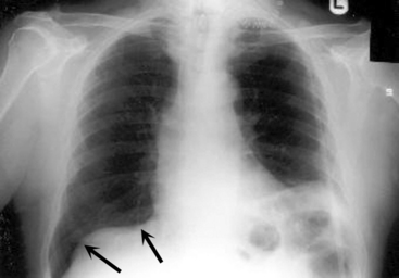
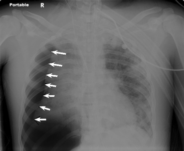
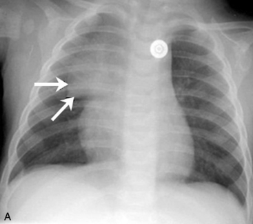
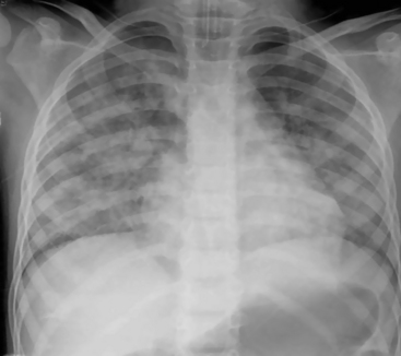
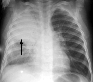
Pneumonia can initially produce a patchy infiltration with fluffy margins. The presence of air bronchograms within the infiltrate can confirm the impression that the opacification is caused by intrapulmonary disease.14 If the pneumonia causes obliteration of the cardiac border, the pneumonia must be in contact with the heart (Fig. 10-17). The portion of the heart that is obliterated will help describe the location of the pneumonia within the lung (see Table 10-2).14
Frequently, pneumonia will later cause more segmental or lobar disease, with a more homogenous opacification of the involved area of the lung.14 The child may develop air trapping with resultant depression of the diaphragm and increased radiolucency of the lung fields.
Some pneumonias cause a characteristic radiographic appearance that correlates with the child’s clinical history. Most infectious pneumonia in children, regardless of origin, begins with local or alveolar involvement, which is difficult to differentiate from interstitial disease; it can later progress to lobar disease. Lobar consolidation frequently occurs as the result of Streptococcus pneumoniae infection. Staphylococcus aureus infection occurs more commonly in infants younger than 1 year; it typically involves the right lung and can cause development of pneumatoceles (localized collections of intrapulmonary air) or abscesses. Haemophilus pneumoniae is nearly always associated with a pleural effusion. Epiglottitis also can accompany this disease, but is uncommon since the advent of the Haemophilus influenzae type B vaccine (Hib) vaccine. Streptococcus, Klebsiella, and H. pneumoniae also may be associated with empyema or pneumatocele formation.14
Aspiration pneumonia usually develops in the portion of the lung that is dependent at the time of aspiration. The radiographic changes following the aspiration are related to irritation and inflammation caused by the aspirated material and to the development of pneumonia. A diffuse aspiration process characteristically produces patchy opacification in the lung bases and perihilar infiltrations.14
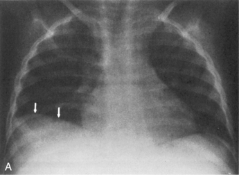
The presence of a unilateral hyperlucency is most often a result of a pneumothorax. A small pneumothorax is more readily observed on an expiratory chest film, because the child’s lung volumes are smaller and the normal pulmonary vascular markings are crowded together (see Fig. 10-2, B). Thus, the difference between the vascularized lung fields and the avascular, radiolucent pneumothorax is intensified on an expiratory film. A pneumothorax may also be more readily discerned in an upright film, because free pleural air will rise toward the apex of the lung.
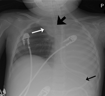
If the child is supine when the radiograph is taken, free pleural air will tend to collect along the diaphragm and the anterior aspects of the thorax (compare Figs. 10-7 and 10-10). In addition, the interface between the pneumothorax and the lung will be in the same plane as the chest radiograph, so a distinct border (or density contrast) between the two may not be apparent. However, a pneumothorax should be considered if an extremely radiolucent area lacking in vascular markings is noted along the diaphragm, along the pleural edge or tracking along the cardiac silhouette.
If the pneumothorax is significant, the underlying lung will collapse, and the trachea and mediastinum will be compressed and shifted away from the side of the pneumothorax. Because the pneumothorax occupies volume, the hemidiaphragm on the involved side of the chest often will be flattened or displaced downward (see Fig. 10-10).
Lung abscesses and pneumatoceles can develop as a result of pneumonia. They both produce circumscribed collections of air within the lungs. The increased radiolucency from an abscess occurs as the result of necrosis. The pneumatocele can also result from necrosis or air trapping.14
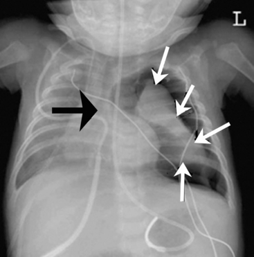
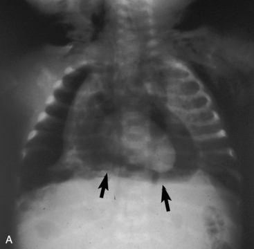
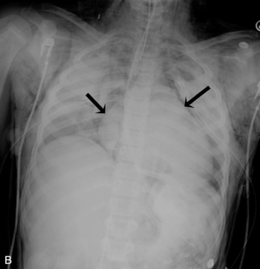
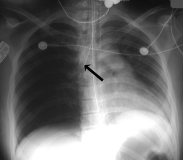
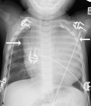
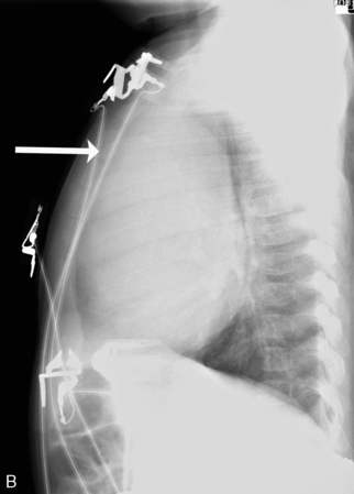
A pneumopericardium is a collection of air within the pericardial sac surrounding the heart. It is usually identified easily because it appears as a radiolucent border between the radiopaque pericardial sac and the radiopaque heart, with the radiolucent border tracking underneath the cardiac silhouette outlining the diaphragm (Fig. 10-18, A).12 In comparison, a pneumomediastinum is a collection of air within the mediastinal space, characterized by streaked radiolucencies over the border of the mediastinum that outline the cardiac silhouette and great vessels. These radiolucencies then extend into the neck and elevate the parietal pleura along the mediastinal borders (Fig. 10-18, B). A pneumomediastinum should be distinguished from a pneumopericardium and a pneumothorax. In pneumopericardium, air can be present underneath the heart, but does not enter the neck.
Children with a diaphragmatic hernia may demonstrate abnormal densities and lucencies within the thorax. Generally, these children have hypoplasia of both lungs. The lung on the side of the diaphragmatic defect is compressed by abdominal contents during fetal life. The heart and other intrathoracic contents shift to the opposite side, thus compressing that lung during fetal life. Even after correction of the diaphragm hernia, the hypoplastic lungs may not completely fill the thorax, so radiolucent areas will surround the lung tissue.27
Identification of tubes, catheters, and wires
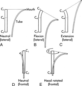
If the child is intubated, the position of the tracheal tube should probably be checked first. The radiopaque tip of the tube should be located approximately 1 to 2 cm above the carina or approximately at the level of the third rib. Because the position of the tracheal tube relative to the carina will change with a change in head position, it is important to note the position of the head when the radiograph is taken. The optimal head position is a neutral and midline position, with no neck flexion or extension. The tip of a tracheal tube will be displaced downward or further into the trachea when the neck is flexed, and it will move upward if the neck is extended or if the head is turned to one side (Fig. 10-19).15
If the tip of the tracheal tube is positioned too near the carina, especially if it is near the carina despite extension of the neck, it can easily slip into the right or left mainstem bronchus. Unintentional intubation of the right mainstem bronchus soon results in hyperinflation of the right lung with hypoventilation and possible atelectasis of the left lung (Fig. 10-20). If the tip of the ET tube is positioned too far above the carina, the tube may inadvertently slip out of the trachea with little patient movement.
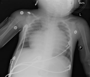
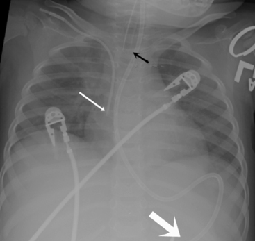
Check the position and integrity of all central venous, pulmonary artery, or intracardiac catheters. Trace these lines along their entire length, because they can migrate distally or be dislodged to undesirable areas (Fig. 10-21). For example, during percutaneous insertion of a subclavian venous catheter, the catheter may advance into the jugular vein and migrate superiorly toward the head instead of inferiorly into the superior vena cava. The right atrial catheter may advance into the right ventricle, which will be obvious from pressure measurements and waveform tracings, or it may rest against the tricuspid valve. The pulmonary artery catheter can migrate distally and become wedged in a small pulmonary artery. Therefore, it is important that the nurse check the location of all catheters and discuss apparent abnormal appearances or the location of these catheters with a member of the medical management team. It is also important to check for pneumothorax following placement, or attempted placement, of a subclavian catheter.
Establish the location of nasogastric or any feeding tubes. In the past, nurses verified the location of the feeding tube with clinical assessment; however, it is now clear that clinical methods alone are inadequate to detect feeding tube misplacement.1 Therefore, the standard of care is to obtain radiographic confirmation of nasogastric tube placement. The nasogastric tube can migrate, especially if it is taped inadequately or if there is excessive patient movement. If, at any point, there is any concern regarding proper placement of the tube, tube position should be verified with a radiograph. The tip of the nasogastric tube and all ports (identified by breaks in the radiopaque marker line) should reside in the stomach. If the tube extends through the stomach and beyond the midline, it is likely in the duodenum or jejunum, and aspiration of the tube yields fluids with a pH > 6 (approximately the same pH as fluids aspirated from the lungs). Nasogastric tubes should be evaluated along their entire length, because occasionally they can become looped in the nasopharynx or cervical region.
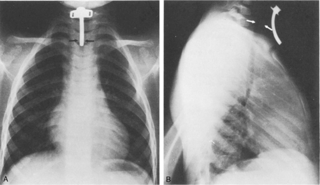
Lateral chest radiographs are often used to evaluate tube placement. As noted earlier in the chapter, AP or PA films are most useful for evaluation of the lateral relationships of structures (Fig. 10-22, A). However, this view occasionally can be misleading because it does not enable evaluation of the AP relationships of structures. The lateral view provides extremely valuable information when evaluating tube placement, because it allows evaluation of the AP relationships of structures (Fig. 10-22, B).
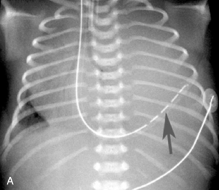
An umbilical venous catheter will curve from the umbilical vein and then into the inferior vena cava (IVC). If the umbilical venous catheter enters the IVC, it should be visible in the right side of the patient’s abdomen, moving toward the border between the liver and the heart. Look for the tip along the right side of the patient’s vertebral column (Fig. 10-23, A, B). The catheter is typically inserted until a good blood return is obtained (approximately 1-4 cm), or it is advanced to the junction of the IVC and the right atrium. The provider should not allow the tip to remain within the shadow of the liver, because it will likely reside in the portal vein or hepatic circulation. That tip location is not recommended, because it would allow infusion of hypertonic or alkaline solutions into the portal vein.27
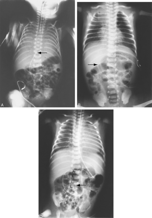
An umbilical artery catheter will enter the umbilical artery and the aorta. If the umbilical artery catheter is in the aorta, it will appear on the patient’s left side of the vertebral column. The catheter tip is advanced until it enters the descending aorta, to prevent obstruction of the femoral or iliac arteries (Fig. 10-23, C). The tip should reside between the levels of the sixth and tenth thoracic vertebrae; lower placement (at the level of the third or fourth lumbar vertebra) is associated with more complications and is not recommended.3
Common imaging studies obtained in critically ill children
Computed Tomography (CT) Scan
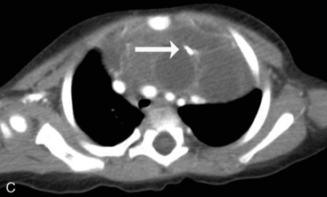
CT is a highly advanced diagnostic procedure that uses x-rays enhanced by a computer to create cross-sectional pictures of the body. Unlike traditional radiographs, the CT rapidly generates a three-dimensional image of the inside of an object from a large series of two-dimensional x-ray images taken around a single axis of rotation. This process creates detailed images of areas surrounded by bone and can show less dense tissues, such as organs and blood vessels (Fig. 10-24). CT completely eliminates the superimposition of structures outside the area of interest into the area of focus. Because of the inherent high-contrast resolution of CT, it allows differentiation of structures that differ in physical density by less than 1%. CT can be enhanced by use of intravenous iodinated contrast material, which allows accurate evaluation of the vascular structures and can give information about enhancement of lesions.
1 American Association of Critical Care Nurses. American Association of Critical Care Nurses Practice Alert: verification of feeding tube placement. Alisa Viejo, CA: American Association of Critical Care Nurses; 2005. Accessed on July 11, 2011 at: http://classic.aacn.org/AACN/practiceAlert.nsf/Files/FT%20Placement/$file/Verification%20of%20Feeding%20Tube%20Placement%2005-2005.pdf
2 American College of Radiology Panel. American College of Radiology Thoracic Imaging Expert Panel Report. Reston, VA: American College of Radiology; 2002.
3 Barrington K.J. Umbilical artery catheters in the newborn: effects of position of the catheter tip. Cochrane Database Syst Rev. 2000. CD000505
4 Barsness K.A., et al. The positive predictive value of rib fractures as an indicator of non-accidental trauma in children. J Trauma. 2003;54:1107-1110.
5 Beckstrand R.L. Understanding chest radiographs of infants and children: the AIR systematic approach. Crit Care Nurse. 2001;21:54-65.
6 Collins J., Stern E. Chest radiology: the essentials. Philadelphia: Lippincott Williams and Wilkins; 2007.
7 Daffner R. Clinical radiology: the essentials. Baltimore: Lippincott Williams and Wilkins; 1993.
8 Des Jardin T.R. Cardiopulmonary anatomy and physiology: essentials for respiratory care, ed 4. New York: Delmar; 2002.
9 Felson B., Weinstein A.S., Spitz H.B. Principles of chest roentgenology: a programmed text, ed 2. Philadelphia: WB Saunders; 1970.
10 Finholt D.A., et al. The heart is under the lower third of the sternum: implications for external cardiac massage. Am J Dis Child. 1986;140:646.
11 Fink B.W. Congenital heart disease: a deductive approach to its diagnosis, ed 3. Chicago: Mosby-Year Book; 1991.
12 Fleisher G., Ludwig S., Henretig F., et al. Textbook of pediatric emergency medicine, ed 5. Baltimore: Lippincott, Williams & and Wilkins; 2006.
13 Heller R.M., et al. Exercises in diagnostic radiology, ed 2. Philadelphia: WB Saunders; 1987.
14 Kirks D.R. Practical pediatric imaging, ed 3. Philadelphia: Lippincott-Raven; 1998.
15 Kuhns L.R., Poznanski A.K. Endotracheal tube position in the infant. J Pediatr. 1971;78:991.
16 Mettler F., et al. Primary care radiology. Philadelphia: Saunders; 2000.
17 Novelline R. Squires’s fundamentals of radiology, ed 6. Cambridge, MA: Harvard University Press; 2004.
18 Orlowski J.P. Optimum position for external cardiac compression in infants and young children. Ann Emerg Med. 1986;15:667.
19 Poznanski A.K. The chest. In Poznanski A.K., editor: Practical approaches to pediatric radiology, ed 2, Chicago: Year Book, 1976.
20 Raffensperger J.G.: Esophageal atresia and tracheoesophageal fistula. . Swenson’s pediatric surgery. ed 5, New York; Appleton-Century-Crofts:1992
21 Silverman F.N., Kuhn J.P. Essentials of Caffey’s pediatric X-ray diagnosis. Chicago: Chicago Year Book; 1996.
22 Squire L.F. Fundamentals of radiology, ed 6. Cambridge, MA: Harvard University Press; 2004.
23 Stanger P. Cardiac malpositions. In Rudolph A.M., editor: Pediatrics, ed 18, Norwalk, CT: Appleton-Century-Crofts, 1987.
24 Sutton D. A textbook of radiology and imaging, ed 6. New York: Churchill-Livingstone; 1998.
25 Swischuk L.R. Imaging of the newborn, infant, and young child, ed 5. Philadelphia: Lippincott Williams and Wilkins; 2005.
26 Swischuk L.R. Emergency imaging of the acutely ill or injured child, ed 4. Baltimore, MD: Lippincott Williams and Wilkins; 2000.
27 Trotter C., Carey B. Radiology basics: overview and concepts. Neonatal Netw. 2000;19(2):35-47.