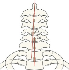
Cervical spine
Analysis: the checklists
Injuries are most often missed because of poor radiographic technique and/or inaccurate film interpretation1,2,4–6. Most errors are avoidable5. Missed C-spine abnormalities occur most commonly at the top or at the bottom of the C-spine1,2.
□ Whatever the level of violence, C-spine injuries frequently occur at the C1–C2 level1,3,4,6.
□ The most common fracture in elderly patients following a fall is a high cervical injury1,3.
□ Between 9% and 26% of patients with one fracture or dislocation of the spine will have further fractures demonstrable radiographically at other levels5.
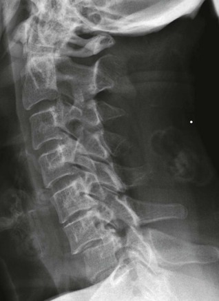
Priority 1: Lateral view checklist
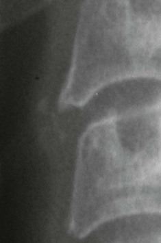
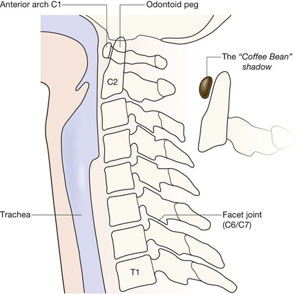
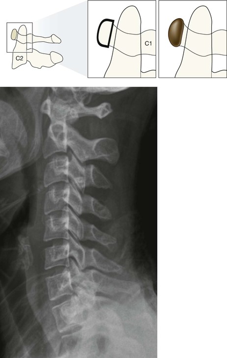
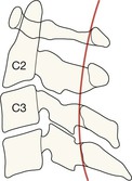
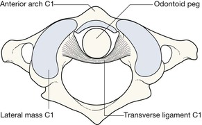
Identify the odontoid peg and assess its position and anatomical relationship to the C1 vertebra. Overlapping structures (eg mastoid, ear lobes, C1 vertebra) can make this difficult. Questions 1–5 will help you to overcome this.
Ask yourself ten important questions:
2. Have I identified the anterior arch of the C1 vertebra (the “coffee bean”)?
3. Is the anterior cortex of the odontoid peg (the Peg) closely apposed to the “coffee bean”?
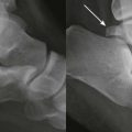
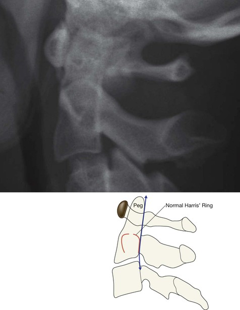
6. Is Harris’ ring7 normal? A break in either the anterior or posterior margin of the ring indicates the high probability of a fracture of the Peg/body of C2 (p. 176).
7. Are the posterior arches of C1 and C2 intact?
8. Are the other vertebrae (C3–C7) intact (p. 192)?
Questions 2 and 3.
Recognising the anterior arch of C1 is key to detecting the abnormalities that may involve the C2 vertebra.
The arch looks like a small coffee bean, and is always easy to identify on the lateral view.
The gap between the Peg and the coffee bean should not exceed 3 mm in adults or 5 mm in children1.
This is a normal lateral view.
Potential Pitfall: Line 3 will sometimes show a slight step at the C2 level, particularly in children8.
Apply this rule: this step should not be more than 2 mm posterior to the smooth arc as it is traced upwards between C3 and C1 vertebrae.
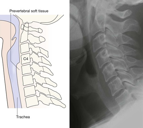
Question 10. Are the pre-vertebral soft tissue shadows normal? The soft tissue shadow7,9–11 anterior to the vertebral bodies has a characteristic configuration and width. Any bulge or local increase in width indicates haemorrhage and connotes an important injury.
NB: The absence of a bulge does not exclude a ligamentous or bone injury. Indeed, even with a major injury, a soft tissue bulge due to a haematoma is fairly rare.
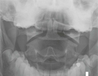
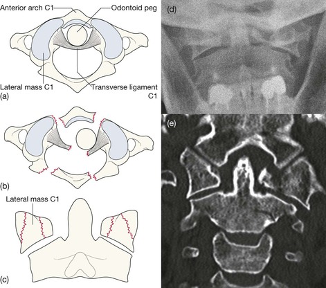
Priority 2: AP Peg view checklist
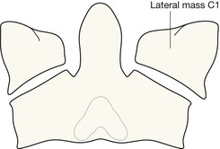
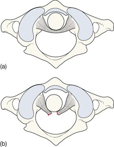
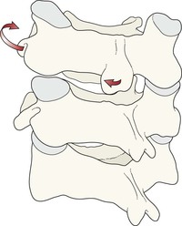
The anatomical arrangement of the C1–C2 articulation allows extensive neck rotation whilst providing maximum stability. This stability depends on the integrity of the ligaments, particularly the C2 transverse ligament. Various other ligaments enable C1 vertebra to be held in the optimal position above the body of C2 vertebra. Any deviation from this alignment indicates either ligamentous disruption or a broken vertebra.
Ask yourself three important questions:
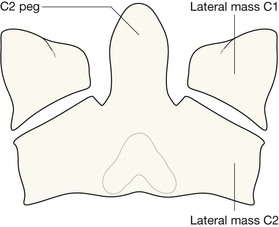
1. Do the lateral margins of C1 align vertically with the adjacent lateral margins of C2?
2. Are the spaces on each side of the Peg approximately equal?
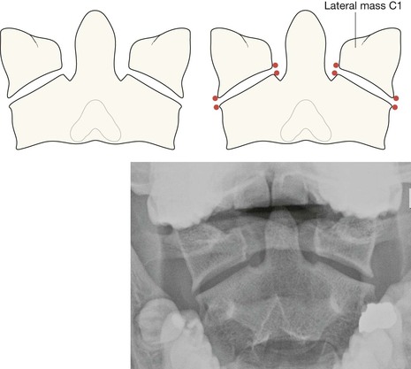
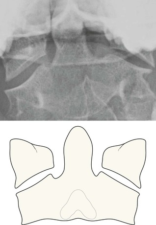
Normal anatomy of the C1–C2 articulation. Looking down from above.
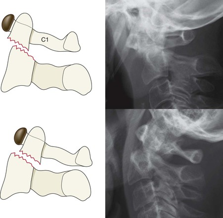
If the lateral masses do not align vertically, then there could be several possible explanations.
First consider subluxation due to ligament rupture.
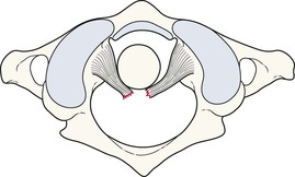
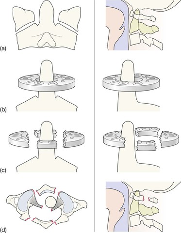
Second, consider fracture of the body of C1; either isolated to a single lateral mass or to a burst fracture of C1 (a Jefferson fracture).
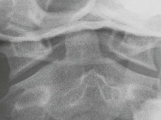
Finally, consider a developmental variation or just simple rotation of a normal neck (see p. 182), as shown on this AP Peg view.
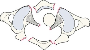
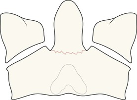
Question 2: Frequent pitfall.
Slight rotation of the neck may cause the space on each side of the Peg to appear unequal. However, if the lateral masses of C1 and C2 remain normally aligned then the asymmetry can be attributed to rotation rather than indicating damage to the transverse ligament (p. 191).
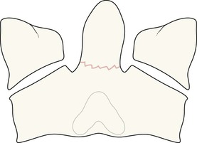
Question 2: Pitfall.
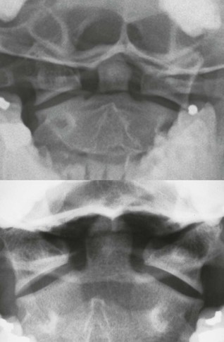
Occasionally, asymmetric alignment of a lateral mass will be present; ie the edges of the adjacent C1/C2 lateral masses do not line up perfectly. This might suggest vertebral subluxation. However, non-pathological causes for this finding do occur: either some slight positional rotation of the neck, or a developmental variation in the size of the C1 and C2 lateral masses1,12–14. In most instances it is fairly easy to decide whether an offset on one side of the C1–C2 articulation is simply developmental… just check whether there is any offset on the other side. If the lateral masses line up normally on the other side then developmental asymmetry is the likely explanation.
Question 3: Pitfall—the Mach effect.
It is very common to see a thin black line crossing the base of the Peg or the top of the Peg. This is an optical illusion15 resulting from the overlapping shadows of superimposed structures. This line is known as a Mach band or a Mach effect. Be aware of this line.
But, be careful…
The inexperienced observer should always seek advice before too readily dismissing any line in this area as a Mach artefact.
Another artefact.
The apparent vertical fracture through the Peg is an artefact. It is caused by the gap between two of the teeth (incisors).
Priority 3: Long AP view checklist
The lateral and Peg views are the most useful images. The diagnostic return from the long AP view, in terms of abnormalities detected, will be considerably less. In addition, it is easy for the unwary to read too much into the AP view.
Ask yourself two questions:
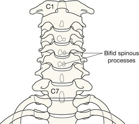
1. Are the spinous processes in a straight line?
If not, consider unilateral facet joint dislocation (see p. 194).
2. Is the space between adjacent spinous processes approximately equal?
A warning: if a space is more than 50% wider than the space immediately above or below, this is highly suggestive of an anterior cervical dislocation16. In practice this observation is most useful in the severely injured patient whose shoulders have obscured some of the vertebrae on the lateral radiograph17. It can provide an important warning that the neck must be managed very carefully until a lateral view or CT has accurately defined the alignment of the vertebrae.

The common injuries
Injuries at C1
The C1 (Atlas) vertebra is a vulnerable structure.
Injuries at C2 involving the Peg
Evidence from the lateral view
▪ A line (fracture) crossing the Peg. Usually seen across its base.
▪ Any misalignment in the anterior or posterior cortex of C2.
▪ Any break in the anterior or the posterior margin of Harris’ ring (p. 176).
Injuries involving the body or the posterior elements of C2
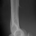
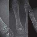
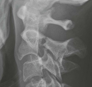
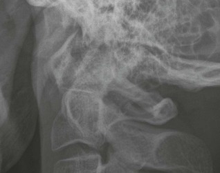
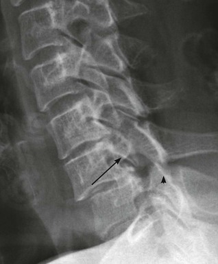
C2 Hangman’s fracture8.
A bilateral fracture through the pars interarticularis of C2 vertebra. Unstable injury caused by hyperextension. Historically consequent on hanging. Now typically results from a motor vehicle accident with (eg) the forehead striking the dashboard. In this patient there is also a fracture of the body of C3.
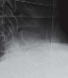
Oblique fracture through the body of the C2 vertebra.
Sometimes this causes the anterior-posterior width of the body of C2 to be increased18 (the so-called “Fat C2“ sign).
C2 subluxation due to rupture of the transverse ligament
Fractures C3–C7
Including spinous process fracture, vertebral body compression fracture, and hyperflexion teardrop fracture.
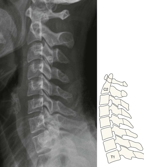
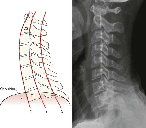
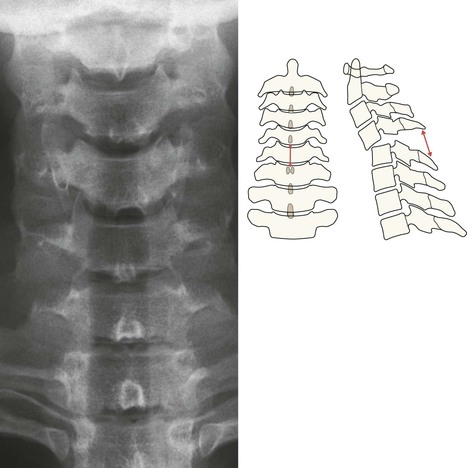
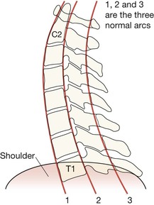
The cardinal rule: The lateral radiograph must always, always, include a well visualised superior surface of the T1 vertebra. Many errors1,3,5 occur because the top of T1 has not been included on the radiograph. Check the lateral view as described on p. 174.
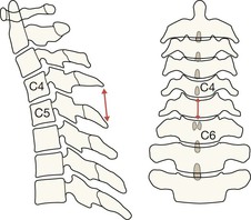
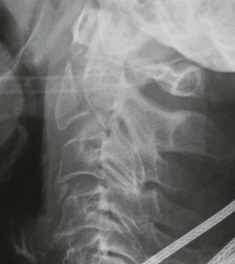
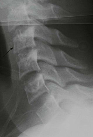
Subluxations/dislocations C3–C7
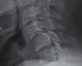
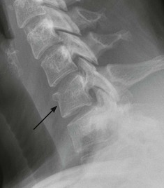
Unilateral facet joint dislocation.
Consequent on a distraction–flexion force with a rotational element. Commonly overlooked on radiographs.
Look for:
▪ AP view: spinous processes out of line.
▪ Lateral view: 10–20% forward subluxation (at the C6/C7 level in this patient).
Then:
Explaining unilateral facet joint dislocation
Pitfalls
On the AP Peg view
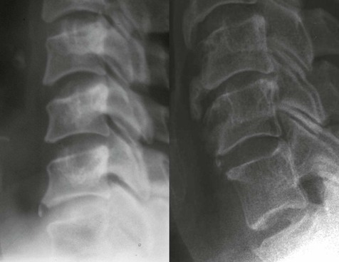
Developmental variants
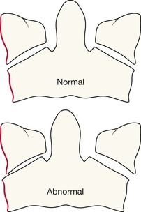
A vertebra (arrow) may appear slightly narrow anteriorly with loss of the normal square or rectangular outline. This can mimic a compression fracture.
Sometimes this narrowed appearance is due to old trauma. Occasionally it is due to persistence of the normal but slightly wedged shape that is often present during adolescence19.
Anterior opacity
A small calcified opacity anterior to a vertebral body can be mistaken for an avulsed fracture fragment. Sometimes it is simply a remnant of an old secondary ossification centre19 (left). An age related osteophyte can also produce a similar appearance (right). When such an opacity is detected, an experienced observer should review the radiographs.
Spasm related—delayed instability
Following trauma, severe pain and spasm may make it difficult to exclude a significant injury to the posterior ligament complex. Muscle spasm can hold the neck in an anatomical position and mask ligamentous rupture. Instability may only become evident after a few days when the spasm has reduced.
It is therefore important that any patient with severe pain and spasm who appears fit for discharge and is put in a collar should be asked to attend again in a few days for further evaluation. Lateral views in flexion and extension might form part of that evaluation. These additional radiographs must be taken under close clinical supervision. If they remain at all equivocal, an MRI examination should be obtained in order to exclude a ligamentous injury.
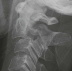
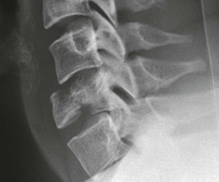
Age related changes
Age related degenerative changes are very common over the age of 40. Distinguishing between changes due to cervical spondylosis and those resulting from an acute injury is not always easy.
The age related appearances shown below are frequently present in the middle-aged and the elderly.
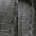
Anterior subluxation of a vertebra secondary to facet joint degenerative change (at several levels on this radiograph). There is no simple way of distinguishing this from traumatic subluxation. In most cases, correlation of the clinical symptoms and signs with the site of the radiographic abnormality will provide reassurance. In some cases an injury should be assumed until an experienced observer has reviewed the radiographs20.