CHAPTER 70 Cervical Instrumentation
Anterior and Posterior
Overview
In the late 1890s, Hadra of Galveston, Texas, stabilized a cervical fracture-dislocation in the first modern report of spine instrumentation.1 He later used this technique in Pott disease.2 For the next 100 years, cervical instrumentation remained limited to various posterior wiring techniques, of which Rogers’ technique was the most frequently employed.3 In the 1980s, wiring patterns began to include corticocancellous bone struts for added extension stiffness.4 In the last 2 decades, rigid, segmental fixation, including lateral mass and pedicle screws, has dominated.
The era of anterior instrumentation began after Robinson and Smith5 popularized the anteromedial approach to cervical disc disease in the 1950s. The simple plating systems that evolved from appendicular stabilization were fraught with loosening, backout, and other, devastating soft tissue consequences. Dedicated anterior cervical plating systems were first described in the 1970s. Bicortical screw purchase decreased screw backout and instrumentation failure rates but added the risk of canal penetration and cord injury risk. In the 1980s, unicortical locking mechanisms increased bone purchase, while preventing screw migration.6
Cervical instrumentation continues to evolve with new disc replacement systems, dynamic and low-profile anterior plates, cervical cages, and resorbable implants. Although promising, some of these newer technologies have been implemented without evidence of added benefit. Before recommending an implant system, American surgeons must consider its U.S. Food and Drug Administration (FDA) status (Tables 70-1 and Table 70-2). Often a device is cleared for some, but not all, of its intended indications. The reasoning for FDA decisions is often obscure and bureaucratic and does not reflect only safety or efficacy issues. The device’s package inserts should be read by surgeons, and questions should be directed to the manufacturer’s legal counsel or to the FDA (1-800-638-2041).
TABLE 70–1 U.S. Food and Drug Administration (FDA) Status of Forms of Cervical Spine Instrumentation
| Type | FDA Status* |
|---|---|
| Anterior Instrumentation | |
| Upper cervical spine | |
| Dens screws | A |
| Lower cervical spine | |
| Anterior plates | |
| Locked plates | A |
| Variable angle plates | A |
| Dynamic plates | A |
| Resorbable implants | I |
| Anterior cages | |
| Threaded interbody cages | A |
| Vertical mesh cages | A |
| Cervical disc arthroplasty systems | A |
| Posterior Instrumentation | |
| Upper cervical spine | |
| Occipitocervical systems | |
| Wiring systems | A |
| Plating systems | A |
| C1-2 instrumentation | |
| Gallie | A |
| Brooks | A |
| Magerl (C1-2 transarticular screws) | A |
| Harms (C1 lateral mass with C2 pedicle screw) | A |
| Lower cervical spine | |
| Lateral mass plating and rodding systems | O |
| Cervical pedicle screw and rod constructs | O |
| Laminaplasty fixation systems | |
| Miniplates (as bone graft containment systems only) | A |
| Suture anchors | O |
| Wiring systems | |
| Interspinous wiring | A |
| Facet wiring | A |
| Bohlman triple wiring | A |
* FDA status refers to the most common use of the device as described in the chapter text. Virtually all of these devices have FDA-approved uses. The status of these devices is constantly evolving. A, approved; I, investigational; O, off-label.
TABLE 70–2 U.S. Food and Drug Administration (FDA) Classes
Biomechanics Introduction: Selecting a Biomechanically Correct Implant
The most common, preventable cause of instrumentation failure is related to errors in surgical judgment. Typically, modern implants are overengineered for their designated function. Direct failure of the implant is more likely because of improper selection or fatigue. The average spine cycles 3 million times per year.7,8 If bone healing fails to occur, all implants ultimately fail, either at their anchor points in the bone or in the material itself. The novelty and technical challenge of safe implant placement should not divert the surgeon’s attention from meticulous preparation of the fusion bed and grafting technique. Occasionally, misplaced implants fail. Careful surgical exposure and intraoperative radiographic confirmation reduce misplacement (Table 70–3). More typically, failure occurs when the surgeon fails to understand fully one of the following four things:
TABLE 70–3 Important Factors in Selection of Cervical Implants
In contrast to typical fracture healing, which passes through Hunter’s stages of bone repair (inflammation, soft callus, hard callus, and remodeling), most modern cervical implants seek primary bone healing in which osteon cutting heads cross segmental gaps directly.9,10 This approach requires near-anatomic alignment and rigid stabilization. Excessive strain or poor bone-to-bone contact stimulates fibrous tissue deposition and, ultimately, construct failure. Successful use of cervical implants requires understanding of their biomechanics.11–13
No clear line divides a “stable” from an “unstable” spine. In serial sectioning studies, White and colleagues14 concluded that more than an 11-degree increase in sagittal angulation or more than 3.5 mm of sagittal plane translation represented instability. These values are most helpful in the acute trauma setting but are less meaningful with chronic destruction, such as infection. In many cases, cervical instrumentation is meant not to correct any innate spinal instability, but rather to reverse or prevent iatrogenic instability associated with decompression. Because each anatomic structure contributes to normal stability and kinematics, it is important during decompression to minimize surgical disruption of intact structures.15 A classic example of iatrogenic spinal destabilization is postlaminectomy kyphosis.16 The difficulty in treating this condition fostered interest in laminaplasty.
The surgeon needs to account for specific patient factors when planning cervical instrumentation. On one hand, children have excellent healing potential and may require less rigid fixation.17 On the other hand, even with excellent graft carpentry and implant placement, osteoporosis increases segmental motions and decreases construct pullout and fatigue strength.18 Insertional torque, pullout strength, and bone mineral density are highly correlated.19,20 Good bone mineral density has a greater positive impact on pullout strength than bicortical purchase.20 Adding polymethyl methacrylate (PMMA) to the screw tract significantly increases the torque and pullout strength of the screw.21,22 Bone loss may affect pedicle screw fixation more than C1 lateral mass fixation because pedicle screws engage cortical bone rather than the cancellous bone seen in the lateral mass.23 More rigid fixation may be required in association with other physiologic factors, such as challenged healing environments after chemotherapy and radiation therapy. Larger patients, poorly compliant patients, diabetics, and smokers may require a more aggressive, rigid implant strategy.24
Early attempts at surgical fixation were complicated by infection, devascularization, inadequate metallurgy, and metal allergy. Better antisepsis, soft tissue handling, and materials evolved. Subsequently, a limited understanding of bone biology and mechanics resulted in poorly conceived implants and techniques. Over time, biomechanical studies improved implant design, although they underestimated the importance of soft tissue and muscular tension. Most biomechanical research is limited by virtue of its ex vivo nature. Cadaveric, animal, or plastic spines are tested in laboratory settings with various pure or complex loads, but these studies do not take into account the importance of muscle forces, tissue healing, or the possibility of gradual ligamentous relaxation (creep).25,26
It is important to limit unnecessary exposure, denervation and devascularization of the paraspinal muscles. Compromised extensor musculature allows collapse into kyphosis above or below the instrumentation.27 Careful muscular repair may protect the construct.28 In the posterior cervical spine, a multilayered closure that includes the suboccipital triangle and ligamentum nucha improves muscular balance, decreasing eccentric implant loading.27,29
Additional important surgical techniques to augment fixation include increasing the strength of any spinal construct with added fixation points, triangulated placement, and aiming for the dense subchondral bone of the vertebral endplate. Extending the duration of postoperative immobilization can also decrease the likelihood of implant failure.30 The relative merits of unicortical versus bicortical screw purchase continue to be debated.31 In anterior and posterior applications, bicortical screws exhibit significantly greater holding power in terms of immediate pullout strength and fatigue resistance.16,32–34 Even in the trauma setting, unicortical fixation maintains reduction and confers high fusion rates.35 The advantages of bicortical purchase are magnified in osteoporosis, in wide decompression with potential instability, in multilevel procedures, and when fixation points are limited.19,36,37
Biomechanical Principles and Functional Modes
The ultimate tensile strength of an implant material refers to the area under its stress-strain curve up to the point where elastic deformation becomes plastic deformation. That is, ultimate tensile strength is the maximum stress a material can sustain without changing shape. This value is different for different materials and ranges from 50 MPa for trabecular bone to 650 MPa for titanium.12 Ultimate tensile strength of a material may be altered during surgery. An implant’s integrity can be compromised by repeatedly bending and unbending it. In addition, titanium is particularly sensitive to notching. The material properties of an implant are also affected by manufacturing elements such as drill holes, structural imperfections, and surface irregularities. Hardness is a surface characteristic that refers to the ability of a material to resist plastic deformation. Hardness can be enhanced with surface coating, but improper handling may destroy the surface coating and compromise implant hardness.
During the 1950s, Danis refined the principles of internal fixation.38 Stable internal fixation fulfills the spine’s local biomechanical demands without concomitant external immobilization. Fixation strategies can be subdivided by implant constraint. The locking mechanism of a constrained system rigidly binds the individual components together (e.g., the screw and plate). Maximum rigidity is achieved by segmental fixation of each vertebra to such a constrained system. A nonconstrained construct is fixed only at the ends of a multilevel construct or includes nonrigid connections between the screws and longitudinal member (e.g., rod or plate).
Spinal implants function in one or more modes (Table 70–4). The principle mode is defined by the location of the device on either the flexion or the extension side of the spine and by the principle mechanism of loading. The degree to which stabilization is required depends on the spine’s mechanical deficits. The role of an anterior cervical plate varies depending on the quality of the interbody grafting. When the spine remains unable to sustain compressive forces, a strong, rigid, bridging implant, applied to either the anterior or the posterior columns, serves as the weight-bearing column. The most common cervical bridging implants are multilevel, segmental, rigid posterior screw-rod systems that are designed to compensate for multilevel anterior metastatic disease or difficult-to-reach, anterior cervicothoracic or occipitocervical lesions.39 Posterior lateral mass plates or rods are more typically used in neutralization mode. To decrease strains across bone healing surfaces, the neutralization implant shields flexion and axial loading forces, while minimizing torsional bending and shearing loads.
Adapted from Aebi M, Thalgott JS, Webb JK: AO ASIF Principles in Spine Surgery. Berlin, Springer, 1998, p 243.
Only 36% of cervical axial loads are borne anteriorly, whereas 32% are borne by each of the posterior articular pillars.40 Despite the relative importance of the articular pillars, the mobility and heavy weight of the head relative to the small size of the cervical bony elements underscore the crucial role of the anterior column in construct stability. When comparing “loose” with “tight” grafts, graft status has been shown to predict overall construct stability and plate effectiveness.41 Excessive anterior distraction decreases posterior column load transmission and subjects the anterior graft and vertebral bodies to excessive loads.42,43 In trauma cases, at least 30% of the endplate area should be covered to maximize stability.44 Similarly, endplate preparation affects graft support and axial loads.45,46
Cortical screws typically exhibit a smaller major diameter, decreased pitch, and a more shallow thread than cancellous screws. Pretapping the hole before screw insertion reduces thread-bone interface microfracture and improves holding power, but this requires an extra step. Self-tapping cortical screws confer similar holding power and have become standard.22,47 The cutting flute at the screw’s tip limits thread contact, however, and may require 1 to 2 mm increased depth of penetration. Cancellous screws provide more surface area for bone purchase by increasing major diameter and pitch. Because insertion compacts the trabecular bone, cancellous screws are not tapped.
Torque applied through the screwdriver rotates the screw clockwise, advancing it along its predrilled path. Screw advancement creates an axial compression force against the cortex or plate. On average, insertion applies 2500 to 3000 N.48 Over time, living bone remodels, slowly decreasing compressive force. External forces magnify this innate loss of holding power.
In rigid, locking plates, the screw head is locked to the plate through secondary metal-on-metal threads, a Morse taper, or an external blocking system. The fact that these screws function mechanically more like a bolt than a screw implies that the axial force generated during insertion is not critical. The simplest of these designs act like internal-external fixators.32,49 Longer screws improve fixation.50
Relevant Anatomy for Spinal Instrumentation
The cervicocranium includes the skull base, atlas, and axis. The size, shape, and location of the cervicocranial joints allow more motion than the joints in the subaxial spine and render arthrodesis more challenging.51,52 The bony elements of the cervicocranium, beginning with the occiput, are unique. The clivus ends in the basion, the anterior border of the foramen magnum. The opisthion refers to its dorsal border. From the foramen magnum, the occipital squama curves 90 degrees cranially toward the inion (or external occipital protuberance [EOP]).
The occiput-C1 articulation includes convex occipital condyles lateral to the foramen magnum articulating with the concave C1 lateral masses. Normal occipitocervical extension is limited to 21 degrees when the occiput abuts the C1 posterior arch.53,54 More than 8 degrees of rotation between the occiput and C1 is pathologic. In children, the flatter occiput-C1 joints are less able to restrict motion, predisposing them to injury.55
Atlantoaxial motion occurs through two sets of two joints. First, the slightly convex inferior facets of the axis meet the slightly convex superior facets of the atlas. These joints are oriented in the horizontal plane and have no interlocking bone to prevent subluxation. They allow 43 degrees of rotation, nearly half of normal cervical rotation.56 The second set of atlantoaxial joints arises from the cranial projection of the odontoid projecting into the axis ring. The dens acts as the focal point of a network of ligaments providing resistance to translation, flexion, extension, and rotation. Dens resection leads to vertical and atlantoaxial instability.57
The lower cervicocranium (C2-3) transitions into the more homogeneous subaxial patterns.58,59 The C3-6 vertebrae exhibit a uniform configuration but gradually increase in size distally. The vertebral bodies are roughly twice as wide as they are deep. Each contains a body; paired pedicles and articular masses; laminae; and a single, spinous process. The transverse process projects laterally from the superolateral aspect of the body and anterior surface of the articular mass and contains the foramen transversarium. The transverse process ends in anterior and posterior tubercles. At C6, the prominent anterior (carotid) tubercle can be palpated for intraoperative localization.
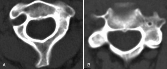
Morphometric data from 100 computed tomography (CT) studies revealed mean vertebral body widths of 24.6 mm in men and 23.0 mm in women.60 The narrowest vertebral bodies measured 17 mm in men and 14 mm in women. In the midsagittal plane, the average anteroposterior diameter was in 18 mm in men (smallest 13 mm) and 16 mm in women (smallest 10 mm). A morphometric analysis of critical cervical pedicle dimensions recorded a wide range of values and only fair interobserver correlation.61 Transverse angulation was fairly constant at 40 degrees. Relative to the lateral mass axis, C3 and C4 pedicles were oriented superiorly, whereas C6 and C7 were oriented inferiorly. The dorsal entry point of the pedicle on the lateral mass, defined by transverse and sagittal offset, had similar mean values with wide ranges and variable topography. Sufficient variation exists to preclude safe pedicle instrumentation using topographic landmarks alone. Ludwig and colleagues61 recommended laminoforaminotomy or image guidance to place these screws.
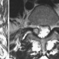
Because bone size varies considerably, preoperative planning using axial and sagittal images decreases the risk of screw placement. It is important to verify that the C2 isthmus is large enough to accommodate a 3.5-mm screw. If bony element size is questionable on magnetic resonance imaging (MRI), a 2-mm cut CT scan limited to the levels of surgical interest should be obtained. It is important to specify that the CT gantry be reangled to be parallel the endplate at each disc level. Clear preoperative measurements of the bony elements allow larger screws to be employed, improving pullout and fatigue strength characteristics. Similarly, preoperative planning allows improved screw trajectory to incorporate better triangulation and subchondral bone purchase. Upper cervical anterior plating may benefit from coronal CT or MRI above C3 because anatomic variation is considerable and may make this technique inadvisable in 20% of cases.62
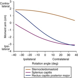
The uncinate process projects cephalad from the inferior mid-cervical vertebral endplates. The immediately superior vertebral endplate receives the uncinate via a contiguous lateral indentation. Together, the process and indentation form the synovial uncovertebral joint (of Luschka). Biomechanically, the uncovertebral joints regulate extension and lateral bending. The posterior uncovertebral joint has a secondary role in torsional control.63,64
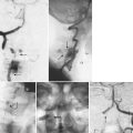
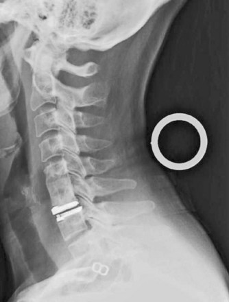
Successful and safe occipitocervical instrumentation requires a detailed understanding of spinal vascular anatomy. Placement of occipital screws risks dural sinus injury. Venous sinus injury is especially likely with screw placement within 1 cm of the EOP.65 The internal carotid artery runs a mean 2.9 mm from the anterior C1 lateral mass and is at risk with Magerl and Harms C1 screw constructs.66 Internal carotid artery injury could lead to life-threatening hemorrhage and stroke, although there are no clinical reports of such injury to date. In a retrospective review of 50 random contrast-enhanced CT scans of the head and neck, the artery was considered at least at moderate risk of injury in 58% of cases.67 Medial screw angulation decreases risk.
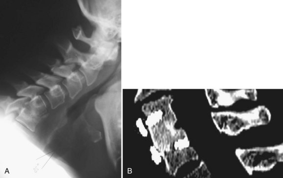
Vertebral artery injury may occur with anterior and posterior cervical procedures. Although clinically evident injuries are rare, catastrophic consequences include fistulas, pseudoaneurysm, cerebral ischemia, and death.68,69 Because the vertebral arteries are paired, injury to one rarely results in significant neurologic deficit. If intraoperative vertebral artery injury is suspected, it is imperative not to attempt exposure or screw placement on the contralateral side, for fear of inadvertent injury to the other vertebral artery. In anterior procedures, too lateral a dissection within the vertebral body puts the vertebral artery at risk.69 It is important to mark the midline so that inadvertent excessive lateral dissection is avoided. Posteriorly, the vertebral arteries are vulnerable to injury during insertion of Magerl and C2 pars and pedicle screws as the drill bit traverses the C2 body. In patients with rheumatoid arthritis in particular, a high rate of ectatic and variable arterial courses has been reported and may preclude safe screw placement in 20% of cases (Fig. 70–1).68,70,71
Before any significant cervical reconstruction procedure, preoperative investigation of the course of the vertebral artery is mandatory.72 Although recommendations vary, the advent of endovascular repair has prompted many spine surgeons to request an intraoperative vascular surgery consultation for a suspected vertebral artery injury. For many of these injuries, local bleeding is controlled, and the patient is taken to the vascular suite for stent placement. Permanent occlusion or ligation should be considered only if the contralateral vertebral artery provides adequate collateral circulation.
Another important anatomic factor to be considered with cervical spine instrumentation is the issue of individual variation. In children, standard implant sizes may be too large. Because the fusion potential in children is so high, however, instrumentation may not be required. Onlay bone grafts alone are a good option in most pediatric cases with limited instability.73 Typical adult internal fixation is usually possible for children older than 12 years and often impossible in children younger than 6.74–76 Some implants have been modified for use in small children, such as craniofacial miniplates.76
Significant interindividual variability also affects posterior reconstruction options at the cervicothoracic junction. Typically, Southwick and Robinson anteromedial exposure is difficult below T1-2.77 Even in cases in which the disc space can be safely reached, orthogonal screw placement is affected by the manubrium.78 In the study by Sharan and colleagues79 of 106 consecutive MRI studies, a bell-shaped curve while T3 was often cranial to the sternal notch, a straight trajectory was limited to the T1-2 disc space. Transmanubrial or trans-sternal approaches have been proposed to increase exposure to T3, but these approaches are associated with significant morbidity.80 Below T4, a formal thoracotomy is often required. In one study, the size of the thoracic outlet, as measured by the instrument manubrial thoracic distance, served as a key guide to the optimal anterior approach.81 Marked individual variability of the cervicothoracic angle and the level and cranial extent of the superior manubrium (e.g., in short-necked and long-necked patients) greatly affects selection, ease, and safety of anterior approaches.79,82
Percutaneous placement of cervical instrumentation from anterior and posterior approaches is being reported with increasing frequency in the literature.83 To protect the midline tension band, lateral mass screw constructs have been implanted via tubular retractor systems.84 In posterior cervical reconstruction, smaller, midline open approaches may complement percutaneous screw delivery.
Fluoroscopy and Navigation for Cervical Spine Instrumentation
Safe instrumentation of the cervical spine requires avoidance of vascular and neurologic structures that are often not exposed for routine implant placement. Historically, intraoperative fluoroscopy has been used to locate the correct level, to optimize spinal alignment, and to assess screw trajectory. Fluoroscopy can also be used “live” to guide entry point selection or after implant placement to confirm acceptable positioning. Some techniques, such as cervical disc arthroplasty, require “live” fluoroscopy to ensure proper implant centering and alignment. Other indications for continuous or pulsed “live” imaging include cervical vertebroplasty and débridement of distant structures (Fig. 70–2).85,86
At the occipitocervical and cervicothoracic junctions, overlying bony structures such as the jaw and shoulders make adequate visualization with fluoroscopy difficult.87 Other limitations of fluoroscopy include increased operating room time, possible sterile field contamination, and radiation exposure.88 Deciding in which cases intraoperative fluoroscopy is “necessary” is controversial.89–91 In one study of 419 cervical pedicle screws, 17 were malpositioned.89 The authors of that study concluded that pedicle axis and en face views improved safety by increasing accuracy. Even with intraoperative imaging, malposition rates of 2.7% to 34% have been reported.90,92–94 In another series, the accuracy of intraoperative anteroposterior fluoroscopy was compared with use of bony landmarks (uncovertebral joints) when centering a cervical disc prosthesis.95 Postoperative CT showed acceptable accuracy with anatomic alignment alone. Other studies have devised various intraoperative guides to improve aim and placement.96
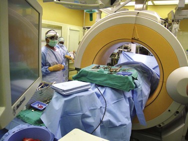
Overlapping anatomic structures, difficulty imaging the cervicothoracic junction, and the desire for intraoperative axial images have fostered increased interest in three-dimensional fluoroscopy.87 Intraoperative CT simulation was found to have 100% concordance with postoperative CT.97 The bulk of the equipment and the radiation exposure limit the utility of these systems in real-time imaging applications. Typically, they are used at the end of the procedure to document appropriate implant positioning, or they can be used as part of a frameless stereotactic guidance system.98 Although these systems continue to evolve rapidly, significant controversy remains as to their accuracy in cervical applications.23,99
In addition to improving the safety of screw insertion, computer-aided spinal navigation has fostered enthusiasm for smaller incisions and less soft tissue mobilization.100 These systems allow the surgeon to assess screw position or trajectory with real-time slices through preoperative CT.101,102 A cadaveric study compared the accuracy of C1-2 transarticular screws inserted with frameless stereotaxic method versus standard methods. The authors of the study concluded that frameless stereotaxy improved transarticular screw placement and potentially allowed safe placement of instrumentation in patients previously considered too risky for such surgery.71
In a clinical series of 19 complex cervical reconstructions, a surface matching registration algorithm allowed 22 C1-2 transarticular screws, 31 cervical pedicle screws, 10 high thoracic pedicle screws, and one C1 lateral mass screw to be placed without any significant misplacement of hardware.103 Ludwig and colleagues61 found computer guidance more accurate than either using topographic landmarks or performing a laminoforaminotomy in obtaining accurate cervical pedicle screw placement. Computer guidance systems may be particularly helpful in patients with previous surgery, deformity, or destructive processes that obliterate landmarks.104
Limitations of computer navigation include displacement of bony targets with drilling forces, excessive cervical mobility requiring frequent reregistration, small structure size at the limits of device accuracy, steep trajectories required for drilling and hardware insertion, and outside device pathways.105 Most authors conclude that navigation improves, but does not eliminate, the risk of critical screw malpositioning. The surgeon must understand the principles of the tracking system to prevent misinterpretation of computer-generated information.106 Navigation systems should be used only by experienced surgeons who can continue the procedure with conventional techniques if necessary.
Anterior Spinal Instrumentation
Marked anatomic and biomechanical differences between the occipitocervical and the subaxial spine result in very different implants. In contrast to posterior cervical implants, all anterior implants are constrained by limited purchase sites, sagittal profile concerns, and the limited extensibility of most surgical approaches. Anterior fixation points are limited to the vertebral body and endplates. Anterior cervical pedicle and occipital condyle screws have been described but are technically challenging and infrequently used.62 Bulky implants may cause swallowing difficulty or respiratory compromise. Currently, anterior reconstruction options can be divided into direct dens fracture fixation, anterior load-bearing implants, and plates. Load-bearing implants, including disc replacements, bone struts, and cages, reconstruct defects created by discectomy and corpectomy procedures.
Anterior Screw Stabilization of the Upper Cervical Spine
In the cervical spine, stand-alone screw fixation is used most frequently to provide rigid internal fixation of unstable dens fractures to preserve C1-2 motion, avoid extensor muscle dissection, and eliminate graft harvest morbidity associated with posterior C1-2 fusion. Dens screw fixation is indicated mainly in widely displaced type II fractures.107 Before C1 lateral mass fixation, dens screw fixation was specifically recommended in patients with concomitant C1 ring fractures to avoid posterior fusion to the occiput. Direct anterior stabilization is associated with decreased blood loss, less postoperative pain, and reduced morbidity compared with posterior fusion operations.108 In patients with incomplete reduction with traction, direct, open anterior reduction may be attempted. These maneuvers are performed with fluoroscopic guidance using an entry point significantly caudal to the injury. The technical challenges associated with anterior odontoid fixation sway many surgeons to treat incompletely reduced dens fractures posteriorly.
Contraindications to dens screw fixation include transverse atlantal ligament disruption and fractures more than 18 months old.107,109–113 Horizontal and posterior oblique fracture lines are much more likely to heal in anatomic position than an anterior oblique fracture line.107 Some “high” type III fractures have enough bone in the body inferiorly to maintain purchase of the base of the screw. In “low” type III dens fractures, screw fixation in the inferior aspect of the C2 body may be tenuous, however, and the screw may break out inferiorly.
The utility of stand-alone dens screw fixation in patients with osteoporosis and elderly patients is controversial.114,115 In a retrospective study, 102 of 110 patients achieved fracture healing.116 The nonunion rates were 4% in patients younger than age 65 and 12% in patients older than age 65. In a retrospective comparison of 29 patients older than 65 with odontoid fracture, all patients with posterior fusion healed uneventfully. Only 8 of the 11 patients treated by anterior odontoid screw fixation healed. Of the 10 patients treated nonoperatively, 7 healed but only after long and complicated courses. The authors concluded that posterior C1-2 fusion was superior to anterior fixation and nonoperative treatment in elderly patients.30
Odontoid screws are inserted using an anteromedial approach. Before surgery, the fracture is reduced with traction. A transverse incision is made just above the level of the cricoid cartilage. The platysma muscle is split longitudinally, and the carotid sheath is identified. Blunt dissection extends the approach cranially. The prevertebral fascia and anterior longitudinal ligament are split in the midline over the axis. The fracture site should be exposed only if open reduction is needed.108 When the fracture is reduced, two 2.0-mm Kirschner wires are placed into the anterior inferior C2 body with biplanar fluoroscopy guidance. One Kirschner wire helps to maintain rotational stability as the other is tapped. A 3.5-mm cannulated cortical screw is placed over the second wire, after which the wire is removed. More recently, percutaneous dens screw fixation has been reported using a cannulated system.117
Odontoid screws average 40 mm in length. Although single screw fixation is sufficient, the tip of the screw must penetrate the apical cortex of the proximal fragment. Postoperative immobilization regimens vary among surgeons from soft collar to halo vest immobilization for 2 months. Direct osteosynthesis of acute dens fractures is associated with an 88% union rate 6 weeks postoperatively.107,108 Remote fractures healed at a significantly lower rate of fusion (25%). Overall, hardware failure occurs in approximately 10% of patients.
Other anterior screw fixation techniques into axis and occiput have also been described.62,118 To date, these techniques seem to be used rarely in clinical situations in which posterior fixation techniques are impossible or have already failed. Anterior screw fixation may add stability in these situations to augment continued attempts at posterior arthrodesis.
Anterior Cervical Plating
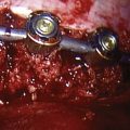
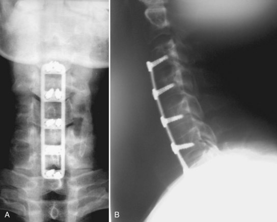
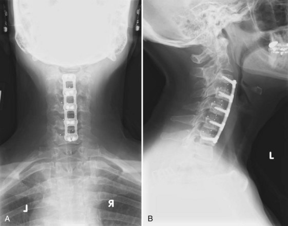
The use of cervical plates has exploded as these plates have become safer and easier to use.119 Benefits include decreased rates of pseudarthrosis, graft extrusion, and graft subsidence (Fig. 70–3).120 Plating allows the patient to minimize or avoid postoperative bracing and begin early rehabilitation.44,121 The drawbacks of cervical plating include cost, soft tissue injury, increased stress on adjacent segments, and stress shielding of the plated bone and graft.122–124
Evolution and Mechanics of Anterior Cervical Plates
In North America, use of plates increased in tandem with interbody allografting.125 Plating reduced pseudarthrosis and graft extrusion rates, justifying multilevel anterior instrumented procedures (Fig. 70–4).6,41,121,126–128 Anterior cervical plates function as a buttress; they do not eliminate all motion. The more levels included in the construct, the more motion occurs along the construct, including plate bending and screw-bone and screw-plate interface toggling.129 Without a plate, spinal flexion loads the graft, whereas extension unloads it. With a rigid anterior plate, these forces reverse. Flexion unloads the graft, and extension loads the strut more than similar degrees of flexion in the unplated state.130 Taller grafts magnify this effect by disc space distraction and diminished posterior column loading.42 Failures typically occur by screw pullout, usually at the inferior end.
The plates used initially in the cervical spine were plates used in the appendicular skeleton. The Caspar plate was one of the first plates specifically designed for the cervical spine. Its parallel screw slots allowed settling, making the Caspar the first axially dynamic plate. At that time, settling was considered undesirable, and the plate was modified by replacing half of its slots with round holes. The screws were not locked to the plate. After cycling, all unlocked unicortical constructs lost significant rigidity.32 Bicortical purchase was required to decrease screw backout.
Typically, differences in grafting technique have a greater effect on overall construct rigidity than the type of plate.131 For most degenerative conditions, nonrigid plates are mechanically similar to locking plates.132 In multilevel and more unstable constructs, failures, including plate and screw fracture, construct pullout, and delayed unions or nonunions, were reported even with second-generation plates.41,121,126,128 Designers responded with thicker and stronger implants.
Even with highly rigid third-generation plates, pseudarthroses continued to occur. Fractures of rigid plates were noted in patients with a solid arthrodesis, and it was hypothesized that plate failure allowed construct dynamization, subjecting the graft to compression forces and resulting in fusion.133 Numerous newer cervical implants seek to control subsidence and bone graft load sharing.
Cervical plates can be placed into three groups. (1) Rigid plates remain popular. Mechanical studies, often in destabilized cadaveric models, continue to support their use over nonlocking and dynamic implants.134,135 (2) Dynamic plates can allow oversettling, resulting in kyphosis and disc space collapse with foraminal narrowing and lower fusion rates.136,137 Some advocates of dynamic plates argue that late rigid plate nonunions are underrecognized.133 (3) Intermediate designs allow variable screw angulation in an otherwise rigid plate. Some plates offer fixed and variable screw insertion methods. One mechanical study found that variable-angled plates had more favorable pullout characteristics no matter what angle for screw insertion was employed.138
Generally, locked cervical plates and dynamic plates are similar in flexion-extension, lateral bending, and torsional stiffness. All plates effectively share load with a full-length graft. As normal graft resorption occurs, a rigid anterior cervical plate may prevent graft load sharing by maintaining a gap between the graft and the host bone.139 If graft subsidence (or controlled impaction) occurs, dynamic plates share load more effectively, however, than locked plates (Fig. 70–5).140–143 The degree of load shielding engendered by rigid plating is controversial.144,145 One cadaveric study reported that dynamic and static plates offered similar overall stabilization, but the dynamic plate performed better in extension and after endplate removal.146 Whether or not dynamic plates are appropriate in trauma and other highly unstable situations continues to be debated.134,146
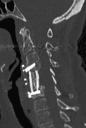
FIGURE 70–5 CT scan showing graft subsidence after anterior cervical corpectomy using an anterior titanium mesh cage.
Dynamic systems offer significant design variability but typically incorporate implant telescoping features (e.g., DOC Rod, Ant-Cer, or Swift Plates) or movement along the spine itself (e.g., Premier or ABC plates). The ABC slotted plate design allows 10 mm each of cephalad and caudad plate migration. Although telescoping implants may be more elegant, one study found them less stiff than slotted designs.140 Some telescoping implants allow graft preloading (Fig. 70–6).43,142
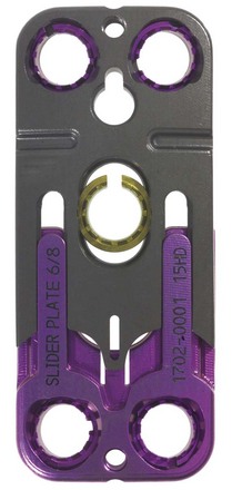
FIGURE 70–6 Anterior cervical dynamic plate (Ant-Cer Plate) allowing controlled collapse.
(Courtesy Zimmer Spine, Warsaw IN.)
Several clinical studies have reported outcomes after dynamic plate fixation. In a series of 34 cases using the DOC system, 85% of the plates subsided, with 61% impacting more than 3 mm, although mean lordosis changed by only 0.4 degree.128 Anterior cervical reconstruction employing dense cancellous grafts and dynamic plates reported a 1-year fusion rate of 96%.147 Average subsidence for one-level fusions was 2.0 mm and for two-level fusions was 3.2 mm. In a prospective analysis of 50 consecutive patients, either a rigid (Orion) or a load-sharing (Premier) plate was used.148 After 12 to 35 months, there was no difference in the fusion rates. Significant differences in pain and functional impairment favored the load-sharing system. Other studies have reported similar or greater pseudarthrosis rates with dynamic plates compared with static plates (16% vs. 5%).137,149
More recently, anterior cervical plates constructed with bioresorbable polymers have been introduced.150 The rationale for use of these plates is to reduce or eliminate complications such as implant migration and failure, imaging degradation, and stress shielding of the fusion mass. The implants theoretically dissolve after their mechanical function has been fulfilled and before long-term problems occur. Questions remain, however, regarding the quality of fixation offered, the variable speed of resorption, and the possibility of chronic inflammatory problems.151
In a preliminary report in small series of patients with short follow-up, resorbable mesh and screw graft containment systems were reported to have acceptable clinical outcomes and 77% fusion rates.152 No significant soft tissue reaction was noted clinically or radiographically in any patients. A retrospective, multicenter trial of 52 patients followed for slightly more than 1 year reported outcomes similar to titanium plates.153 Mechanically, absorbable plates function more as “graft containment” devices than as rigid spine stabilization.154,155 Early, dramatic failures with this type of plate have been described.156
Indications and Rationale
Although the benefits of plating may be agreed on, this does not imply that a plate is “needed” in most degenerative conditions. Good outcome has been reported for fusion without instrumentation, and there is little evidence that routine anterior cervical plating improves surgical outcomes compared with fusion without plating.5,157–160 With proper graft carpentry and immobilization, even unplated corpectomies heal.161 One series of 97 tricortical autogenous iliac crest ACDF procedures reported pseudarthrosis rates of 11% and 28% in one-level and two-level fusions, however, despite 2 months of collar immobilization.162
Disadvantages of cervical plating include cost, the possibility of neurologic injury during placement, an increased risk of soft tissue injury with instrumentation failure, the possibility of postoperative dysphagia, and a higher risk of adjacent segment disease.163,164 Esophageal erosion secondary to screw or plate loosening, although rare, may be fatal.165 Additionally, adjacent segment surgery may require a more extensive dissection to remove the old plate. Newer “extension” plates and all-in-one screw-cage designs may allow previous implant retention without significant biomechanical compromise.166,167
Stand-alone anterior plating after multilevel reconstruction and high-energy trauma is controversial. Anterior plates significantly increase global spinal stiffness and decrease segmental motion after multilevel strut grafting.130 Although excellent radiographic outcomes are reported with one-level or two-level plated constructs, the risk of graft failure increases substantially with additional levels, even with a plate.157,159,168 Ongoing screw-vertebral motion is seen after three-level corpectomy and four-level discectomy cases.169 Although two motion segment constructs are acceptably immobilized by anterior plating, lateral mass screw systems are significantly more rigid in longer constructs.145,170–172 After cycling, range of motion at the lower end of long constructs was found to increase 171% in flexion, 164% in extension, 153% in lateral bending, and 115% in axial rotation. This fatigue failure explains caudal loosening of long anterior plate constructs.169 In multilevel reconstructions, longer and larger diameter screws or supplementary posterior instrumentation should be considered.173
Rather than perform multilevel corpectomies, many surgeons prefer hybrid corpectomy and discectomy decompressions to allow improved restoration of lordosis and to provide additional, mid-construct anchors. Whether the spared ligamentous and bony interconnections justify the additional time and fusion surfaces that must heal is unclear.41,174–177 In a cadaveric study, segmental fixation afforded by three-level discectomy and hybrid discectomy and corpectomy yielded significantly more flexion-extension and lateral bending stiffness than two-level corpectomy.178 In two small studies of four-level and five-level hybrid anterior reconstructions, all patients ultimately had fusion.179,180 The authors concluded that adjunctive, posterior stabilization was not needed when hybrid techniques are used.
Historically, stabilization of the traumatized cervical spine required either posterior stabilization or halo immobilization.181 More recently, anterior plate fixation was reported to obviate posterior stabilization in patients with a flexion-distraction injury and disc herniation.182 Some authors recommend this approach only in patients with good bone quality, using wedged grafts and external immobilization until radiographic fusion is evident.183 In a mechanical study, anterior fixation was “adequate” to restabilize the traumatized segment, but lateral mass plating was even more effective.184
Fusion failure rates increase with age and medical comorbidities.185 Because combined anterior-posterior surgeries are major procedures to recommend to older and sicker patients, halo bracing has been recommended. Halo vests poorly immobilize the lower cervical segments, however, which are the levels most at risk for construct failure. Also, halos can cause additional pulmonary and other medical morbidity.186 Combined anterior-posterior reconstructions must be considered for such cases. Although few outcomes data are available, the results of small series are promising.187 After posterior instrumentation, anterior plating does not confer additional mechanical benefits.169,172,188
Technique
Anterior plates are typically applied through a standard anteromedial approach. A transverse incision generally suffices. In some multilevel procedures, a longitudinal incision along the anterior border of the sternocleidomastoid is required. Optimal screw trajectories may be limited by tension from the midline viscera, especially in men with a large thyroid cartilage. In this setting, adequate fascial release improves implant alignment and decreases retractor pressure.165 Inadequate exposure risks aberrant screw trajectories into the adjacent (usually superior) disc space. Some authors recommend intraoperative fluoroscopy or Kirschner wire placement into adjacent disc spaces to guide subsequent plate and screw trajectory planning.189 Unnecessary dissection or incorrect needle localization may increase risk of adjacent level degeneration.190
A plate of appropriate size should be selected. Depending on the intended screw angulation, the plate should extend no further than the mid-portion of the superior and inferior vertebrae. Adjacent level ossification disorder, an early form of adjacent segment disease, increases with plate impingement on the cranial adjacent segment. In one series of 330 ACDF procedures, Caspar distractor pins, plate impingement on the adjacent disc, and anterior longitudinal ligament stripping all were risk factors for adjacent level ossification disorder, which was seen 6 to 12 months after surgery.191
With longer constructs, holding pins maintain plate alignment while drilling the screw tracts and reduce the risk of plate dislodgment or rotation from drilling. In long constructs, plate malangulation may result in poor fixation at the opposite end of the construct. In a series of 200 patients undergoing one-level, two-level, or three-level ACDF, frontal plane angulation and lateral displacement were not significantly associated with outcomes.192
Before plate application, the surgeon should ensure proper alignment, especially neck rotation, and remove any externally applied traction. Careful plate contouring increases effective buttressing, may decrease swallowing difficulties, and increases the number of screw threads in the vertebral body.193 Overcontouring may risk plate fracture.194
Many surgeons universally use 14-mm screws. Optimally, screw depth should be based on the anteroposterior depth of the adjacent intact vertebrae (12 to 20 mm). If measuring from a CT scan, the surgeon should confirm that the gantry angle simulates the ultimate screw trajectory. Bicortical purchase should be considered in osteoporotic bone or more unstable situations.19 Bicortical screws may better “lever” the spine into lordosis but may also prevent load sharing and increase force on the bone-implant interface.133,193 The biggest disadvantage to bicortical screw fixation is the danger of cord or root injury.49,145 If bicortical screws are to be placed, a screw-tap method should be employed under image intensification control. The posterior cortex should be palpated with a thin Kirschner wire.
Some plates strictly fix the screw trajectory. Others allow a “cone” of variable screw placement. Variable angle plates have been recommended as a means of “dynamizing” the construct.135 Angulation may allow longer screws to be placed with triangulation to enhance pullout strength. Most commonly, a superior and medial trajectory is recommended for the cranial screws, and an inferior and medial trajectory is recommended for the caudal screws. Screws can also be angled into the dense, subchondral bone plate. More recently, a trajectory 90 degrees to the plate has been recommended.138 Proper screw placement in anterior cervical plating cases is often suboptimal if done without radiographic guidance.195 If a screw has inadvertently entered an adjacent disc space, it should be redirected, if possible.
Typically, the plate supplements the grafting procedure. Cervical plates do not compensate for poor grafting technique.8,12 Traditionally, patients undergoing anterior cervical plating procedures were placed in rigid braces postoperatively. More recently, a strong trend toward use of a soft collar or nonbracing has emerged. In a randomized, multicenter trial comprising 257 patients, the nonbraced patients had a higher, but not statistically different, fusion rate than braced patients.196 In another series of patients with multilevel ACDF procedures treated with a dynamic plate, postoperative graft or plate displacement was decreased with the addition of cervicothoracic bracing.197
Outcomes and Complications
Because plating is often recommended to improve fusion rates, the surgeon must be able to identify a solid fusion, a “stable pseudarthrosis,” or a symptomatic nonunion. Plain films do not always reveal subtle signs of nonunion or even motion on flexion-extension views.198 Fine-cut CT scans define bridging trabecular bone better, but with significant radiation exposure. Implants, particularly stainless steel plates or “trabecular metal” cages, cause radiation scatter and make it difficult to see radiographic detail.
The advantage of anterior plates for single-level cervical fusions continues to be debated.162,199,200 When comparing reoperation rates before and after they began routinely using plates with ACDF procedures, Bose200 reported three patients with early graft extrusions and two with symptomatic pseudarthrosis in 48 cases without plates. In comparison, of the 35 plated one-level ACDF procedures with plates, one patient developed displacement, and three exhibited symptomatic pseudarthrosis. Other authors found little advantage in outcomes or fusion rates after one-level cervical plating.126,201 Patients without plates more often exhibited graft collapse with resulting kyphosis.201 Another series of single-level discectomies reported pseudarthrosis rates of 4.5% and 8.3% with and without plate fixation.157 Based on Odom’s criteria, good or excellent results were reported in 91% and 88% of the patients with plates and without plates. Single-level plating is associated with few complications.6,120 After one-level ACDF, routine radiographic assessment may not be warranted in asymptomatic patients.202 Only 2% of asymptomatic patients had construct abnormalities compared with 25% of symptomatic patients.
Fusion rates decrease with increasing levels operated on, and the advantages of plating become more apparent in multilevel procedures. In a two-level ACDF cohort, pseudarthrosis rates were 0% for patients with plates and 25% for patients without plates.158 In three-level fusions, better clinical outcomes and an 18% pseudarthrosis rate were reported in the plated group compared with a 37% pseudarthrosis rate in the group without plates.159
Bone graft collapse or settling into the adjacent endplates after ACDF and corpectomy commonly results in a kyphotic deformity. Plating is superior to nonplating in maintenance of segmental lordosis.201,203,204 In one series, 0.75 mm of graft collapse occurred in patients with plates compared with 1.5 mm in patients without plates.157 In another series of 93 patients undergoing cervical corpectomy without instrumentation, there was a mean loss of 10.4 degrees of lordosis. Sagittal contour was not associated with neurologic decline or functional outcome.204
Complications associated with the addition of anterior instrumentation include the following:
Over the last 15 years, complications with anterior instrumented cervical fusions have become similar to complications for uninstrumented fusions.158,205,206 Cervical instrumentation complications include a 2% to 3% neurologic injury rate, 3% to 45% reoperation rate for implant failure, and 5% to 10% infection rate.207 Today, neurologic injuries and infections from plate application are rare.206,208
Implant failures can occur in 1% to 4% of cases and may result from osteoporosis, bone incompetence from multiple screw insertion attempts, inadequate postoperative immobilization, or excessive postoperative loading.206,208 The rate is proportional to the number of levels fused. Plate rigidity and bicortical screw fixation also affect failure rates.34,145
The impact of well-performed anterior instrumented cervical fusion on the incidence of degeneration at adjacent levels is controversial. One cadaveric study found no difference in adjacent segment motion or pressures between a fusion with or without plate fixation.209 When screws enter the neighboring disc space, however, they may accelerate adjacent segment degeneration.
Esophageal injury from screw displacement has been reported.210,211 Vascular complications may arise from overretraction on carotid sheath or direct injury to the vertebral artery.212 Retraction is especially problematic in older patients with atherosclerosis and may lead to strokes. Injury to the vertebral artery is rare with anterior procedures and is thought to occur with excessive lateral dissection.
Dysphonia and dysphagia have received more attention in the recent literature. Although rates range from 2% to 60% (which may depend on whether and how the question is asked), both are more common in women.213–215 Rates increase with revision and with surgery at more cranial levels.213–215 The degree to which plate placement and thickness affect dysphagia is controversial.214,216,217 If there is a plating effect, it may arise from plate thickness, texture, or merely the increased exposure necessary to insert the plate. One study compared final anterior construct height with preoperative anterior osteophyte height and found no differences in rates of dysphagia.215 When comparing 156 consecutive patients undergoing ACDF with either a thinner, smoother plate or a thicker, rougher plate, dysphagia gradually decreased over 2 years to 0% with the thinner plate and to 14% with the thicker plate.216 Plate removal improved dysphagia in 17 of 31 patients.217 In patients experiencing improvement after plate removal, adhesions were found between the plate and surrounding fascial structures.
Anterior Cervical Cages
Similar to plating, cervical cages have evolved as increasingly complex anterior cervical reconstruction efforts were performed. Structural grafting historically required tricortical iliac crest or autologous fibula harvest. In some countries, allograft bone banks obviated the need for structural autograft bone harvest. In other parts of the world, allograft may not be readily available, and axially stable implants were sought to eliminate autologous harvest.218
Mechanics and Rationale
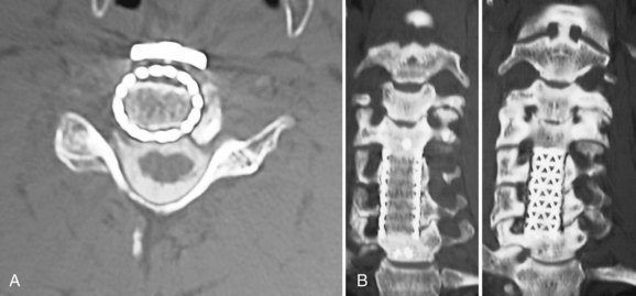
Initially, metallic mesh cages were developed for reconstruction after corpectomy. Eventually, cage materials and geometries rapidly expanded. Currently, there are interbody devices for ACDF procedures, struts to reconstruct corpectomy defects, expandable cages, and cages with built-in plating or screw-in mechanisms. Cage materials include machined allograft, titanium, polyetheretherketone (PEEK), carbon fiber, and trabecular metal (Fig. 70–7).
The ideal interbody cage provides the following:219
Theoretical disadvantages of interbody cages include the following:
Cervical cages come in two main geometries—vertical and horizontal. Typically, vertical implants fill corpectomy defects, whereas horizontal implants reconstruct discectomy gaps. For the latter group, the mechanical goal is distraction-compression via restoration of annular tension.220,221 Implantation technique varies but is not significantly different from traditional bone graft placement. The metallic tines of vertical cages and the threads or texturing of horizontal cages allow better torsion and displacement resistance than an equivalently sized, smooth bone graft.
Cages are subdivided further by shape and material. Horizontal cage designs include screw-in, box, or mesh configurations. Screw-in cages are threaded cylinders such as the BAK-C. Box cages are rectangular with textured bearing surfaces (e.g., Leopard, Syncage). Carbon fiber or PEEK designs are more commonly used today than titanium implants (Fig. 70–8).
Numerous mechanical studies have addressed the relative merits of different cage materials and geometries. In one study, multiple cage types and autologous iliac crest grafts were tested in flexion, extension, axial rotation, and lateral bending in 80 sheep spines. Compared with an intact segment, cages increased flexion stiffness but decreased rotational stiffness. Mesh designs provided greater extension and bending stiffness than screw-in designs.222 Compared with a traditional tricortical autogenous ACDF (Smith-Robinson technique), a single BAK-C offered significantly lower stiffness and failure loads.223 Cage size and placement within the disc space are more important than differences in pore size or materials.224 A fully open cylinder was found to transfer loads more effectively than a central pore in a box design.225
The mechanical benefits of cages over bone graft are small. A cage does not supplant the additional stability afforded by plating.219,226–229 A finite element model compared four implantation methods and found that stand-alone cages offered the least stabilization. The cage with a locking plate was very stiff in all directions. Two dynamic plate configurations reduced flexibility in all directions compared with an intact cage but left significant mobility.230
Disadvantages of cage implantation include difficulty assessing radiographic fusion status. Radiolucent carbon fiber or PEEK cages interfere less with postoperative imaging than titanium mesh cages.231 A more important disadvantage is the expense. In most cases, cages are used in conjunction with, rather than in lieu of, plating.
As with traditional grafting, subsidence has been seen with cages but less so with wide endplate coverage.227,232 Cylindric implants subside significantly further than plate and graft or rectangular cage constructs.219,233 Endplate preservation or limited endplate perforation for vascular ingrowth decreases subsidence compared with more aggressive endplate preparation.45,234
Expandable cages, initially employed after tumor reconstruction, have received increased attention more recently in reconstruction of a degenerative cervical spine. Proponents argue that traditional cages require segmental overdistraction to place the cage and achieve tight endplate contact.235 Distraction in situ allows the cage to be adjusted precisely to the defect. Detractors argue that expandable cages limit bone graft area, add significant cost, and generate high forces that can precipitate adjacent segment fractures.236
Newer hybrid cage devices incorporate plates or screw recesses.231,237 These anchored spacers with integrated screws seek to provide immediate fixation, while maintaining a low implant profile. Operative time may be decreased, and the morbidity of the surgical approach may be reduced by limiting anterior musculature disruption. A biomechanical comparison of an anchored spacer with established devices found no significant differences between the two.167 A retrospective review of 20 corpectomy patients reconstructed with a distractible cage with an attached plate found that stability was achieved in all cases. Good or excellent outcome was reported in 75% of cases with one case of subsidence.238 In anatomic regions with limited anterior access (e.g., cervicothoracic and occipitocervical junctions), formal anterior plating may be difficult. Custom cages decrease the need for perpendicular access to the spine.239
As with anterior plating, interbody bioresorbable polymers have been studied. Results have been mixed.7,151,240 At this point, these devices cannot be recommended for implantation outside of carefully controlled trials.
Implant Selection and Technique Notes
Cervical cages are used to reconstruct anterior spinal column defects. They may be used after discectomy procedures or to fill corpectomy defects after surgery for degenerative, traumatic, or neoplastic indications. Use of nonbiologic materials in the face of active infection is controversial.241 Allograft struts are just as susceptible to glycocalyx or biofilm formation as are metal or PEEK implants. Ideally, autograft should be used in patients with osteomyelitis. Restoration of stability may be more critical, however, than avoiding implants in the case of an infection with significant bone loss. Full débridement of cervical osteomyelitis often requires two-level corpectomy. Because structural autograft harvest contributed to surgical morbidity, titanium and PEEK implants have been used with some success. Typically, surgical indications for anterior cervical cages include the following:
A series of 15 to 24 osteomyelitis patients, including several with epidural abscess, reported success with allograft, titanium mesh cages, and plates. Many of these procedures required radical anterior débridement. Typically, a subsequent posterior screw-rod stabilization and approximately 6 weeks of postoperative intravenous antibiotics are required.241–243 At mean follow-up ranging from 20 to 54 months, greater than 90% fusion rates without recurrent infection were noted in many of these studies. In contrast, one series reported two recurrences in a group of 36 patients with vertebral bone destruction caused by organisms ranging from Staphylococcus aureus to Mycobacterium tuberculosis and treated with expandable cages.244
As with plating, reconstruction with anterior cages is mechanically most vulnerable when carried over multiple levels, when extrusion and subsidence can occur. Cage subsidence was associated with neck pain, plate failure, significantly worse Japanese Orthopaedic Association score, and late neurologic deterioration.218 As with plating, hybrid constructs and multilevel discectomies are more stable than multilevel corpectomy.245
The use of stand-alone cages (e.g., without anterior plating or a posterior rod-screw construct) is controversial. Typically, good clinical outcomes and fusion rates (93.3% to 100%) have been reported despite high subsidence rates.246,247 Subsidence and segmental kyphosis are worst at C6-7.248 In a comparison study, 44% of stand-alone cage segments lost more than 5 degrees of lordosis and subsided more than 3 mm, typically by 3 months postoperatively.249 Outcomes do not seem to be affected by these radiographic findings.249,250 Small series have reported successful use of stand-alone cages adjacent to previous ACDF constructs, however.251
Bone Graft Selection
Cages provide structural support and avoid the chronic donor site pain seen in 0% to 31% of patients undergoing structural autograft harvest.162,252–254 One prospective, randomized clinical study randomly assigned 86 patients with one-level cervical radiculopathy to either cervical discectomy alone or discectomy with threaded cage (Ray cage) insertion.255 At 2 years, 86.1% of cage patients had a good outcome versus 76.7% of simple discectomy patients. The fusion rates were not significantly different (83.3% vs. 81.0%, P = .30). Satisfaction and neck and arm pain were statistically similar. The authors concluded that cages provided little advantage over discectomy alone.
Numerous graft materials can be used with structural cages. Nonstructural (morcellized) iliac crest autograft, often obtained percutaneously, may be placed in or around the cage.256 Local bone from the decompression may also be used. Morcellized allograft, demineralized bone matrix putties, and sponges containing recombinant human bone morphogenetic protein (BMP) 2 have also been used. Many series have reported excellent results after implanting “empty” cages.257–260
Machined allograft cages may not require additional grafting and have compared favorably with autograft in one-level and two-level anterior procedures.261 Many allograft options are available. For discectomy procedures, tricortical iliac crest wedges and small fibular rings predominate. Dense cancellous allograft (e.g., patellar wedge) has been recommended for its open matrix structure, which imparts axial stability comparable to tricortical iliac crest and predominantly cortical fibular grafts, while maintaining a porous structure that promotes vascularization and cellular penetration.262 In one series of 98 patients, dense cancellous allograft was used with one-level and two-level dynamic plating. At 12 months, the fusion rate was 96%. Although there were no allograft or hardware complications, mean subsidence was 2.0 mm for the single-level constructs and 3.2 mm for the double-level constructs.263
In a multilevel ACDF study in alpine goats, threaded intervertebral fusion cages filled with BMP showed a much higher arthrodesis rate and accelerated bone formation compared with either autogenous bone-filled BAK or autogenous bone grafts.264 In humans, enthusiasm for anterior cervical BMP placement has been tempered by postoperative swallowing and breathing problems in nearly a quarter of patients implanted.265 BMPs may also stimulate the resorptive phase of bone healing leading to endplate resorption and increased cage subsidence and migration.266 Another series of 200 retrospectively reviewed patients undergoing one-level to three-level ACDF found a 100% fusion rate confirmed by CT and dynamic x-rays.267 Soft tissue problems included 14 (7%) patients with clinically significant dysphagia and 4 (2%) patients who required repeated operation for hematoma or seroma. As of this writing, anterior use of BMP is not recommended outside carefully controlled investigational review board–approved studies.
For structural autograft or allograft, screw placement into the graft itself should be avoided because this increases the risk of graft fracture.268,269 Some PEEK, carbon fiber, and metallic cages contain holes to allow fixation to an anterior cervical plate. The mechanical benefits of this additional fixation have not been convincingly shown.
Newer cages constructed entirely of osteoconductive materials, such as tricalcium phosphate or trabecular metal, have been described. The crystalline grafts may be more brittle, but have better imaging characteristics than their metallic counterparts. Small studies employing coralline interbody implants have reported variable clinical outcomes, fusion rates of approximately 45%, and high rates of graft fragmentation and subsidence.270–272 Tantalum interbody implants are far less brittle but add considerable scatter, even with CT evaluation. A more recent study randomly assigned 61 patients to ACDF with either a tantalum interbody implant or an autologous iliac bone graft and plating.273 Although 24-month radiologic and clinical outcomes were similar in the two groups, there were considerably more complications in the autologous graft group. Some hybrid PEEK or metal cages incorporate osteoconductive cores of tricalcium phosphate, coralline hydroxyapatite, or similar materials.274
Technique
Wider endplate coverage allows the cage to resist axial compression forces better. The widest cage that fits in the defect should be chosen, especially at lower cervical levels.45,224,248 For some multilevel procedures, different cages may be optimal at different levels.248 Some authors recommend anterior osteophytes be retained to increase load-bearing area of the cage.247 It is unclear whether the axial load-bearing benefits of osteophyte retention exceed detrimental effects on plate prominence or buttressing.
To decrease cage extrusion rates, it is important to achieve a tight interference fit. Excessive traction unloads the articular pillars posteriorly.43 Increasing cage height also increases segmental lordosis, but this may decrease adjacent segment motion.275 When selecting and implanting a cervical cage, the following principles should be observed:
More controversial recommendations include avoiding the following:
Outcomes and Complications
Initial favorable reports in 80 and 135 patients implanted with BAK-C cages reported high fusion rates.276,277 These initial reports were followed by prospective, randomized FDA trials comparing BAK-C cages with uninstrumented ACDF in 344 radiculopathy patients. Virtually all outcomes measures were similar in both groups and were maintained for more than 2 years. The authors concluded that outcomes with threaded fusion cage were the same as outcomes with a conventional uninstrumented ACDF with iliac crest autograft.278 With longer, 4.8-year, follow-up in 103 patents, 95% good to excellent outcomes were reported with a 98.9% fusion rate.279 Lordosis was maintained in 93.8% and increased in 6.2%.
Other, smaller studies have compared rectangular carbon fiber and titanium cages with iliac crest autograft. High fusion rates and equivalent outcomes were reported in all groups. Significant donor site pain was reported in 20% to 33% of the structural autograft patients.256,280,281 An economic comparison found that costs between mesh cages and autograft were “not significantly different” because of the iliac crest harvest morbidity.253 Another prospective, randomized study of 42 cervical interbody fusions found similar results with either an autologous tricortical iliac graft or a cage and that tricortical graft was cheaper.282
Few studies report cage outcomes after corpectomy surgery. Most are retrospective reports of 26 to 34 patients reporting titanium mesh packed with local autograft or allograft chips.243,283,284 Successful use of stand-alone cages in one-level corpectomies is reported, whereas three-level corpectomies or greater typically use adjunctive, posterior stabilization. Fusion rates of 97% to 100% are reported, as are occasional cage extrusions, kyphotic collapse, and postoperative radiculopathy. Most reports conclude that titanium cages provide immediate strong anterior column support with minimal hardware complications and avoid the morbidity of bone graft harvest.
Other prospective, randomized studies have been less enthusiastic about outcome after fusion with interbody cages. In three studies comprising approximately 100 patients randomly assigned to ACDF with a carbon fiber cage or a traditional Cloward procedure with bone grafting, overall pain and disability were similar for both groups.285–287 Although donor site pain was significantly less in the cage group, the fusion rate was also significantly lower. In all three studies, patients with pseudarthrosis reported more severe neck pain than patients with solid fusion.
Anterior cervical reconstruction with cages poses the same risks as surgery without cages.227 Complications such as graft displacement or subsidence with resulting foraminal stenosis occur more frequently in multilevel procedures (up to 33%) and in osteopenic or spastic patients. In these settings, adjunctive, posterior stabilization should be considered.288–290
Cervical Disc Arthroplasty
Cervical total disc replacement (TDR) is one of several emerging motion-preserving technologies in the surgical treatment of cervical degenerative disorders. Although clinical experience is not as great as with lumbar arthroplasty, cervical TDR seems to be becoming more popular.291 Relative to the lumbar spine, differences between fusion and motion preservation technologies are more pronounced in the cervical spine. The cervical lateral masses play a much larger role in axial load bearing than the lumbar posterior elements. The smaller cervical bony endplates pose a challenge for endplate fixation.292 Finally, the anterior airway and posterior spinal cord amplify the risks associated with cervical TDR compared with lumbar disc arthroplasty (Fig. 70–9).
Although various materials such as cobalt-chromium alloy, titanium, and high-molecular-weight polyethylene have been tried in cervical TDR systems, optimal biomaterials have not been identified.293,294 Cobalt-chromium alloy makes postoperative MRI more difficult than titanium.294 The likelihood and effects of wear debris do not seem to be significant concerns in early follow-up studies or in experimental models, but these particles migrate into the periprosthetic and epidural spaces.295 The long-term effects are unknown. More recently, the long-term impacts of metal on metallic lower extremity prostheses have led to a re-evaluation of those devices.296 Concerns about inflammatory reactions and soft tissue and bone destruction from metallic debris and early device failure have been reported after cervical arthroplasty.297
Even within material groups (e.g., metal-on-polyethylene), numerous design questions remain unanswered.292,298 Some systems rely on a midline keel to achieve fixation; others use spikes or endplate texturing. Keels may risk sagittal split fractures, especially in multilevel implantations.299 These devices also vary in terms of the constraint they place on normal segmental motion.298 Typically, more constrained implants require more elaborate endplate fixation methods, but they may also offer more protection of the facets.300 At this time, no device is available that fully restores normal segmental kinematics.292,301 Perfect midline positioning and rotation are required to provide proper motion, regardless of device kinematics.
In contrast to lumbar applications, cervical disc replacements are primarily indicated in the treatment of spondylotic radiculopathy and myelopathy—not axial pain syndromes.302 Contraindications to cervical arthroplasty include active infection, osteoporosis, severe posterior facet disease, and radiographic evidence of mechanical instability or absent motion.
Despite the overall high success rates with traditional ACDF surgery, the level of expectation for widespread implementation of this expensive new technology is very high.302 First, in most younger and active patients, preservation of motion in and of itself is a worthwhile goal and may be associated with decreased postoperative axial pain and improved long-term function. More importantly, there is the possibility of decreased adjacent segment degeneration.303
At the time of this writing, cervical arthroplasty remains a promising, but unproven, technology whose long-term benefits are unclear. Patient selection for arthroplasty is far more selective than for anterior discectomy and fusion procedures.302 Although randomized trials show equivalent outcomes or slight favoring of TDR over ACDF, an analysis of predictors of outcome show that patient factors such as work status and pending litigation have a far greater impact on outcomes than the type of interbody device used.304