[level-membership-for-critical-care-medicine-category]
11 Cardiac Rhythm Assessment and Management
After reading this chapter, you should be able to:
• describe the various arrhythmogenic mechanisms implicated in the development and propogation of cardiac arrhythmias
• recognise the features of the various commonly observed arrhythmias and discuss the aetiological factors that predispose to the development of each
• discuss the actual or potential haemodynamic consequences and prognostic implications of each of the commonly observed arrhythmia types
• describe the general and specific assessment and treatment strategies applicable to each of the various arrhythmia types
• discuss the principles and indications for pacemaker therapy
• recognise abnormal pacemaker activity on ECG and discuss the causes and corrective actions for complications during temporary pacing
• describe the principles and benefits of cardiac resynchronisation therapy (CRT), including the factors which limit the effectiveness of the therapy
• discuss the principles and indications for treatment of arrhythmias including ablation therapies, permanent pacing, cardioverter defibrillators, cardioversion and defibrillation.
The Cardiac Conduction System
The normal heartbeat sequence occurs through rhythmic stimulation of the heart via its specialised conduction system. The sinoatrial node, located superiorly in the right atrium, spontaneously generates an activation current that conducts across preferential right and left atrial pathways (producing a P wave on the surface ECG) and then to the atrioventricular node at the lower interatrial septum. After a brief physiological slowing of the current (to allow the ventricles to be optimally ‘pre-loaded’), the impulse travels to the Bundle of His in the upper interventricular septum before spreading down through the ventricles via the right and left bundle branches. These terminate distally as branching Purkinje fibres which penetrate and activate the ventricles. This ventricular activation (or depolarisation) sequence produces a QRS complex on the surface ECG and subsequent repolarisation gives rise to an electrocardiographic T wave. Pathophysiological processes may disrupt this sequence, giving rise to arrhythmia production.1,2
Arrhythmogenic Mechanisms
Abnormal Automaticity
The action potential of sinus and atrioventricular conducting tissue differs from that of the myocardium in that phase 4 of their action potentials are less stable and possess the property of spontaneous automaticity and consequent depolarisation. This is an important property that allows these tissues to assume the role of electrophysiological pacemaker dominance. However, in some circumstances, such as myocardial ischaemia or cardiostimulatory influences, regional levels of spontaneous automaticity can be abnormally accelerated, stimulating subsidiary pacing cells (such as those within the AV junction and ventricular Purkinje fibres) to override the normal sinus rate.3,4
Triggered Activity
Arrhythmias may occur through the occurrence of abnormal oscillations within the early and late repolarisation stages of the cardiac action potential that lead to the propagation of aberrant ‘triggered’ arrhythmic events. Such oscillations are classified as either ‘early after depolarisations’ that occur during phases 2 and 3 of the action potential or late after depolarisations, which occur during phase 4. Digitalis toxicity, ischaemia, hypokalaemia, hypomagnesaemia and elevated catecholamine levels are the more common causes of triggered activity.5 Excessive prolongation of the action potential duration enhances the risk of such triggered activity and as such these mechanisms are implicated in the development of certain subtypes of ventricular tachyarrhythmias, in particular torsade de pointes (refer to description later in this chapter).
Reentry
The most common cause of tachyarrhythmias is reentry, in which current can continue to circulate through the heart because of different rates of conduction and repolarisation in different areas of the heart (temporal dispersion). Slow conduction through a region of the heart may allow enough time for other tissues which have already been depolarised to recover, and then to be re-excited by the arrival of the slowly-conducting wavefront. Once this pattern of out-of-phase conduction and repolarisation is established, a current may continue to circulate back and forth between adjacent areas, or around a re-entry circuit. Each ‘lap’ of the circuit gives rise to another depolarisation (P wave or QRS complex).4,6 The ultimate rate of the tachycardia depends on the size of the circuit (micro versus macro reentry) and the conduction velocity around the circuit.
Arrhythmias and Arrhythmia Management
Arrhythmias may arise from myocardial or conduction system tissue, and may represent inappropriate excitation or depression of automaticity, altered refractoriness resulting in micro-reentry arrhythmias, or may involve reentry on a larger scale, as between the atria, AV node and/or ventricles.3
The clinical impact of tachyarrhythmias is highly variable and is influenced by the rate and duration of the arrhythmia, the site of origin (ventricular vs supraventricular), and the presence or absence of underlying cardiac disease. As a result, arrhythmias may require no treatment, at least in the short term, or at worst may present as cardiac arrest and require treatment according to advanced life support algorithms (as described in Chapter 24).
Arrhythmias of the Sinoatrial Node and Atria
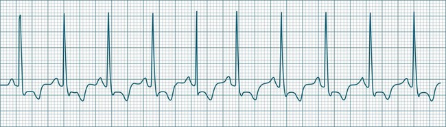
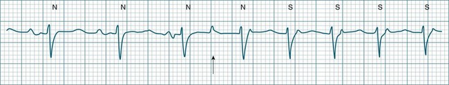
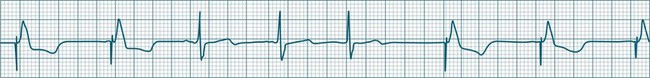
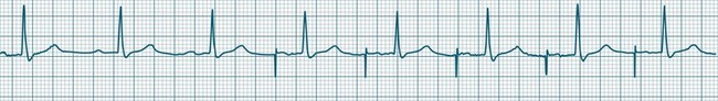
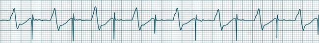
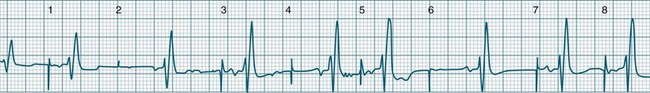
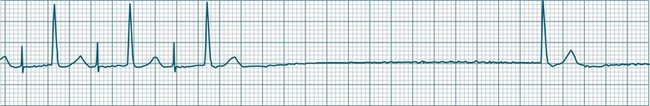
In health, the sinus node controls the heart rate according to metabolic demand, responding to autonomic, adrenal and other inputs, which vary according to exertion or other stressors. In response to needs, the sinus node discharge rate typically varies from as low as 50 beats/min to as high as 160 beats/min. In the conditioned heart (e.g. in athletes), this range extends perhaps down to as low as 40 beats/min, and to as high as 180 beats/min. Peak activity in the elite athlete may even achieve sinus rates of 200/min, though this represents the extreme end of the sinus rate. Sinus rhythm is illustrated in Figure 11.1.

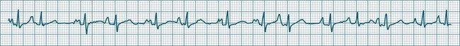
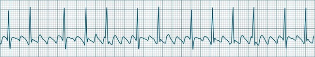
Sinus Tachycardia
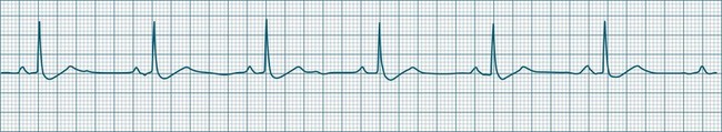
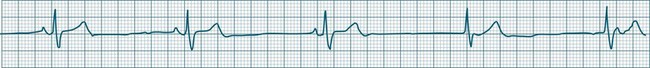
In adults, a sinus rate of greater than 100/min is termed sinus tachycardia and may occur with normal exertion7,8 (see Figure 11.2). When sinus tachycardia occurs in the patient at rest, reasons other than exertion must be sought and include compensatory responses to stress, hypotension, hypoxaemia, hypoglycaemia or pain, in which there is increased neurohormonal drive. Many drugs such as inotropes and sympathomimetics also accelerate the sinus rate. Sinus tachycardia should therefore be regarded as a response to a physiological stimulus rather than an arrhythmia arising from sinus node dysfunction. Treatment is directed at the trigger for the tachycardia, not the tachycardia itself. As sinus tachycardia may point to covert events such as internal bleeding or pulmonary embolism, there should be thorough investigation for unexplained, persistent sinus tachycardia.
Sinus Bradycardia
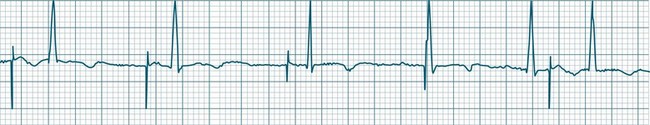
A sinus rate of less than 60 beats/min is termed sinus bradycardia7,8 (see Figure 11.3). In general terms the slower the rate, the more likely it is to produce symptoms related to low cardiac output. Slowing of the rate to less than 50/min is commonplace during sleep, especially in the athletic heart, but is otherwise uncommon. Bradycardia may accompany myocardial ischaemia (especially when due to right coronary artery disease), conduction system disease, hypoxaemia, and vagal stimulation (e.g. nausea, vomiting, or painful procedures). It also accompanies beta-blocker, antiarrhythmic or calcium channel blocker treatment.9 Treatment of sinus bradycardia reflects the treatment of AV block and is covered below under the management of atrioventricular block.
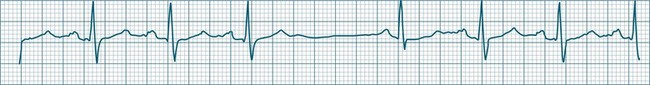
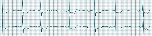
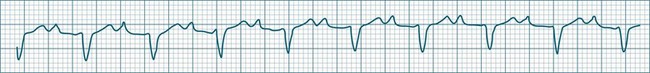
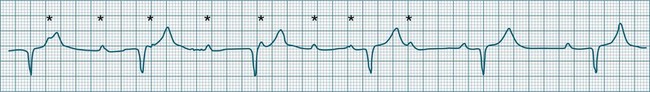
Sinus Arrhythmia
When the rhythm is clearly sinus in origin but is irregular, then the term sinus arrhythmia may be used (see Figure 11.4). Generally, a gradual rise and fall in rate can be appreciated in synchrony with respiration. The gradual rise and fall in rate is important: it distinguishes sinus arrhythmia from the abrupt prematurity with which atrial ectopic beats make their appearance, or the abrupt slowing of the sinus rate seen in sinus pause and sinus arrest. Sinus arrhythmia may accompany sinus node dysfunction but is seen also in the normal heart. Of itself, sinus arrhythmia does not require treatment.
Sinus Pause and Sinus Arrest
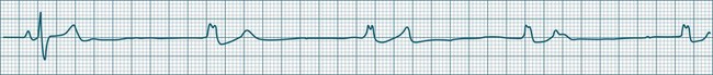
Abrupt interruption to the sinus discharge rate has spawned a variety of descriptive terms, based partly on physiology and partly on severity. Sinus pause is self-descriptive: during a period of sinus rhythm, there is a sudden pause during which the sinus node does not fire.9 The heart rate abruptly drops, during which time there may be bradycardic symptoms. Sinus arrest tends to be used as a descriptor when the sinus pause is longer rather than shorter (usually above 3 seconds) (see Figure 11.5). The longer the period of sinus arrest, the greater the likelihood of symptoms, and syncope is possible.9 Sinus pause may be indistinguishable from sinus exit block (in which there is sinus discharge that fails to excite the atria), as both result in missing P waves. The distinction is academic, however, as both arrhythmias arise from the same groups of causes, and are significant only when they cause symptomatic bradycardia. Pauses in which the P–P intervals spanning the pause are multiples of the pre-pause P-P interval favour the diagnosis of exit block (Figure 11.6).5 Recurrent syncopal pauses may require acute responses for symptomatic bradyarrhythmias (see AV block treatment below). If episodes continue, consideration should be given to permanent pacemaker implantation.
Arrhythmias of the Atria and Atrioventricular Node
The term supraventricular tachycardia (SVT) is often used to group the tachyarrhythmias which arise from tissues above the ventricles. In its more common usage, SVT is thus an umbrella term, to include any of the tachyarrhythmias arising from the sinus node, the atrial tissue or the atrioventricular node.10 However, when a specific arrhythmia can be classified, the specific term is used rather than the more general term SVT. On occasion the electrocardiographic distinction between atrial flutter, atrial tachycardia and atrioventricular nodal reentry tachycardia may be difficult to make, and it may be useful in that context to use the more general term SVT. Supraventricular arrhythmias may occur as single-beat ectopics arising from atrial or junctional tissue, or runs of consecutive premature beats, and thus be termed supraventricular tachycardias. SVTs may be self-limiting (paroxysmal) or sustained (until treatment), recurrent or incessant (sustained despite treatment).
Atrial Ectopy
Impulses arising from atrial sites away from the sinus node (atrial foci) conduct through the atria in different patterns to sinus beats, and so give rise to P waves of different morphologies. These altered P waves define atrial ectopy, and their prematurity, or faster discharge rate, sees them more completely described as premature atrial beats. A characteristic P wave morphology cannot be provided, as ectopy may arise anywhere within the atria, causing upright, inverted or biphasic P waves. Ectopic P waves are often so premature that they become hidden within the preceding T wave. At such times evidence of their presence can be concluded only because they deform the T wave, and because premature QRS complexes of normal morphology follow, suggesting a supraventricular origin of those beats. Premature atrial beats most commonly conduct normally, although they may conduct aberrantly, or not at all, depending on their degree of prematurity and the state of AV nodal and intraventricular conduction (see Figure 11.7).
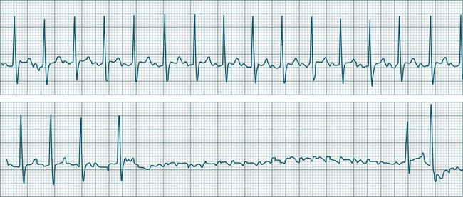
Atrial Tachycardia
A rapidly firing atrial focus or (more commonly) the presence of an atrial reentry circuit may give rise to a rapid rate, which is termed atrial tachycardia. Rates range from 140–230 beats/min and the rhythm is typically very regular.5 P waves may be difficult to identify, as they become hidden in T waves. At such times, the presence of narrow QRS complexes, confirming supraventricular conduction, aid diagnosis and discrimination from ventricular tachycardia. Distinction from other supraventricular arrhythmias may rely on the absence of characteristic features of other SVTs (e.g. the sawtooth baseline of flutter, the irregularity of fibrillation, or the pseudo-R waves and onset pattern of atrioventricular nodal reentry tachycardia). When the atrial rate exceeds the conduction capability of the AV node, varying degrees of AV block occur. Atrial tachycardia may be paroxysmal, sustained or incessant (see Figure 11.8). Symptoms vary and are partly dependent on the rate of the arrhythmia, and the presence or absence of myocardial dysfunction.
Multifocal Atrial Tachycardia
When multiple atrial sites participate in generating atrial ectopic beats at a rapid rate, the term multifocal atrial tachycardia is used (see Figure 11.9). The different foci produce P waves of varying morphology, and typically the strict regularity seen during atrial tachycardia is lost.9 Multifocal atrial tachycardia in particular complicates chronic obstructive pulmonary disease (COPD), as well as other pulmonary diseases as part of the cor pulmonale spectrum.11
AV Conduction During Supraventricular Tachyarrhythmias
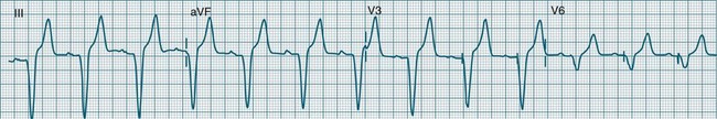
The rapid atrial rates associated with some atrial arrhythmias exceed the conduction capability of the AV node, with the result that not all of the atrial impulses can be conducted (see Figures 11.10 and 11.11). This usually occurs when the atrial rate exceeds 200/min. Thus during atrial flutter, or rapid atrial tachycardia, it is common to see 2 : 1 block or greater. During atrial fibrillation the ventricular response rate rarely exceeds 170/min.
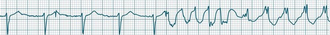
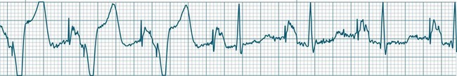
Atrial Flutter
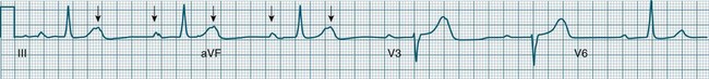
Atrial flutter is a rapid, organised atrial tachyarrhythmia (see Figure 11.11). The atrial rate may be anywhere between 240 and 430/min, but most commonly the rate is close to 300/min.9 At these rates the atrial depolarisation waves (flutter waves) run together to produce the characteristic ECG feature of this arrhythmia: the so-called ‘sawtooth’ baseline, because of its resemblance to the teeth of a saw. This sawtooth baseline is generally best shown in the inferior leads. By contrast, in lead V1 the flutter waves usually appear more like discrete P waves, whilst in leads I and aVL, it may appear more like fibrillatory waves. The atrial rate of close to 300/min rarely conducts on a 1 : 1 basis to the ventricles. Rather 2 : 1, 3 : 1, 4 : 1 or variable levels of AV block intervene to limit the ventricular response rate, often to between 75 and 150/min.9 When the AV block is variable, beats at 3 : 1, 4 : 1 or other ratios are seen together in a single strip. When there is 2 : 1 block, the flutter waves are often concealed within the QRS and/or T wave, and so definite identification may be difficult (see Figure 11.12). At such times, the presence of a narrow QRS tachycardia at a fixed rate close to 150/min is particularly suggestive of atrial flutter with 2 : 1 block. The tendency for flutter waves to appear as discrete P waves in lead V1 may also be useful, as they may be more easily visualised in this lead. Vagal manoeuvres, or adenosine administration, may increase the degree of block and so reveal the flutter waves (Figure 11.12).7,8
Atrial Fibrillation
Atrial fibrillation is a chaotic atrial rhythm in which multiple separate foci either discharge rapidly or participate in reentry circuits, resulting in rapid and irregular depolarisations that are not able to gain complete control of the atria.7,9 Discrete P waves (representing the coordinated depolarisation of the atria) are therefore not seen; rather there is a continuous undulation of the ECG baseline (fibrillatory waves at a rate between 300 and 500/min), reflecting the continuous erratic electrical activity within the atria. This erratic, uncoordinated electrical activity results in uncoordinated contraction, and the atria can be seen not so much to contract but to quiver continuously. It is this quivering (fibrillatory) motion that gives atrial fibrillation its name.
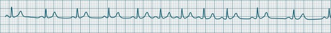
The irregularity of the atrial rate results in an irregular arrival of impulses at the AV node and, as a result, conduction to the ventricles at irregular intervals.7 Thus, a hallmark of atrial fibrillation is the marked irregularity of the ventricular rhythm. The ventricular response rate to the rapid atrial rate is determined by the state of AV nodal conduction, and in patients with normal AV conduction is often in the range of 140–180/min (rapid or uncontrolled atrial fibrillation) (see Figure 11.13). Alternatively, when AV conduction is impaired, or limited by drug effect, slower ventricular rates are seen. When atrial fibrillation is accompanied by a ventricular rate less than 100/min, it may be termed slow (or controlled) atrial fibrillation. Atrial fibrillation is a common significant arrhythmia12 and, while not usually immediately life-threatening, it contributes significantly to morbidity, especially in patients with existing cardiac failure. The loss of organised atrial contraction (atrial kick) as well as rapid rates deprive the ventricles of adequate filling, and so hypotension and low cardiac output may result. Consequent pooling of blood in the atria enhances the risk of emboli formation and stroke. In addition, the incomplete atrial emptying results in congestion of first the atria and then the pulmonary circulation, and contributes to dyspnoea, increased work of breathing, and hypoxaemia. Patients with left ventricular failure rely more heavily on atrial kick, and so symptoms and the severity of their heart failure typically worsen during atrial fibrillation. At times, atrial fibrillation is debilitating in this group, and shock and/or acute pulmonary oedema may develop.
Antiarrhythmic therapy aims at reverting atrial fibrillation, or to limiting the ventricular rate (rate control) even if fibrillation is persistent.12 For patients with chronic atrial fibrillation in whom adequate rate control cannot be achieved pharmacologically, it is sometimes necessary to perform radiofrequency ablation of the AV node itself. Permanent pacemaker implantation is therefore also necessary.
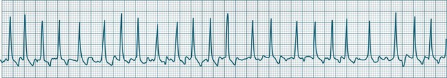
Atrioventricular Nodal Reentry Tachycardia
Atrioventricular Nodal Reentry Tachycardia (AVNRT) is the most common type of paroxysmal supraventricular tachycardia (PSVT), accounting for greater than 50% of cases of PSVT.5 (Note that PSVT as used here does not include atrial flutter or fibrillation). AVNRT is more common in women (75% of cases), more often in younger than older patients, and in some individuals there is an identifiable link to stress, anxiety or stimulants. As the name suggests the arrhythmia arises because of reentry involving the AV node. Normally, atrial impulses reach the AV node via both slow and fast AV nodal pathways which link the atria to the AV node proper. The resultant PR interval is <0.20 sec. In AVNRT, the trigger mechanism is a premature atrial ectopic which is blocked by the fast pathway because of refractoriness. Conduction into the AV node and to the ventricles is still possible by the slow AV nodal pathway, but the resultant PR interval will be quite long (AV delay plus slow conduction into the AV node). Following this atrial ectopic with its long PR interval is the onset of the tachycardia.13
The tachycardia develops because the initiating impulse, the atrial ectopic, is delayed in reaching the AV node. Once it does reach the AV node it conducts to the ventricles, but also now finds the previously refractory fast pathway recovered and able to conduct retrogradely back to the atria. There is now a functional circuit for reentry between the atria and the AV node. Impulses conduct slowly into the AV node, lengthening the PR interval, but on reaching the AV node conduct just as quickly to atria as to the ventricles. As a result, the P waves appear at much the same time as the QRS.13 In some instances of AVNRT it is not possible to identify P waves at all because they are hidden within the QRS. Often, however, the P waves can be seen distorting the final part of the QRS complex, appearing as small R waves in V1 and small S waves in lead II. Because they are P waves rather than part of the QRS, the ECG appearance has been dubbed ‘pseudo R waves’ in V1 and ‘pseudo-S waves’ in lead II13 (Figure 11.14). AVNRT is typically regular, and most commonly at rates between 170 and 240/min but may be slower. The QRS is narrow unless there is concommitant bundle branch block. AVNRTs sometimes respond well to vagal manoeuvres, including coughing, bearing down, and carotid sinus massage. Adenosine may interrupt the arrhythmia, and other AV blocking drugs or antiarrhythmics may be necessary to prevent recurrence. Elective cardioversion is sometimes necessary, and if the arrhythmia is chronically troublesome, slow pathway ablation may be undertaken.5,13
Nursing Management of Atrial Arrhythmias
General symptoms of atrial tachyarrhythmias include: palpitations, dyspnoea/tachypnoea, fullness in the throat/neck, fatigue, lightheadedness, syncope, chest pain and angina symptoms and nausea and/or vomiting. Management of atrial tachyarrhythmias includes: (a) searching for and correction of the cause; (b) rate control limiting the ventricular response, even if the arrhythmias cannot be suppressed;14,15 (c) reversion of the arrhythmias by vagal manoeuvres, medication, cardioversion or overdrive pacing; (d) ablation;16 (e) prophylactic anticoagulation; and (f) prevention of recurrence using cardiac resynchronisation therapies such as biventricular pacing.17
Bradyarrhythmias and Atrioventricular Block
Bradycardia, a slowing of the ventricular rate to less than 60 beats/min, may occur in the form of slowing of the sinus node rate or failure of conduction at the level of the AV node. As the rate slows, escape rhythms should intervene, limiting the severity of the bradycardia. However, these may also fail, rendering the patient asystolic or with catastrophic bradycardia.18,19
Bradycardic Influences
Conduction system depression may occur with abnormal autonomic balance (increased vagal or decreased sympathetic tone), decreased endocrine stimulation (reduced catecholamine or thyroid hormone secretion), or from pathological influences such as conduction system disease, or congestive, ischaemic, valvular or cardiomyopathic heart diseases. Many biochemical and pharmacological factors cause conduction system depression with resultant bradycardia.18 The causes of bradycardia and AV block include:18
• drugs: virtually all antiarrhythmics, calcium channel or beta-blockers, and digitalis preparations may contribute to bradycardia and AV conduction disturbance to a greater or lesser extent
• decreased sympathetic activity, or blockade of neural transmission (e.g. spinal injury, anaesthetic or receptor blockade)
• increased parasympathetic activity: vagal stimu-lation such as nausea, vomiting, carotid sinus pressure, increased abdominal pressure, femoral manipulation.
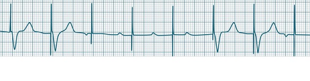
In the absence of stimulation by the SA node, other tissues within the conduction system and myocardium can generate cardiac rhythms at rates slower than the normal sinus rate. Thus sinus node failure need not severely compromise the patient, as the inherent automaticity of the AV node can generate a (nodal) rhythm at a rate of 40–60 beats/min. Similarly, should the AV node fail and the ventricles receive no stimuli, there is an additional layer of protection, as the ventricles themselves can generate (ventricular) rhythms at rates of 20–40 beats/min.7
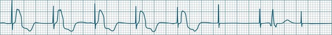
Junctional Escape Rhythms
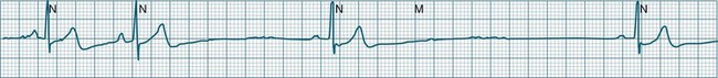
This term describes the AV node response to bradycardia. When sinus bradycardia falls to a rate slower than the inherent automatic rate of the AV node, then the junctional tissues fire.7,9 Typical rates are 40–60/min but may be slower, as the cause of the primary bradycardia may also suppress the firing of escape foci. Intraventricular conduction usually follows the same pattern as had been present before junctional rhythm and so the QRS is unchanged from how it was previously, although occasionally aberrant ventricular conduction may occur, widening the QRS complex. P waves may or may not be evident and are often inverted because of retrograde conduction, as atrial activation spreads from the AV node and upwards through the atria. These P waves may at times be seen in advance of the QRS (at shorter than normal P–R intervals), within the ST segment, or may be hidden within the QRS complexes (see Figure 11.15).
Ventricular Escape Rhythms
When either the sinus or AV node fails, and stimulation of the ventricles does not occur, the ventricles can autoexcite themselves, usually at a rate of 20–40 beats/min (Figure 11.16). Symptoms of bradycardia commonly accompany these idioventricular rates, and acute rate restoration may be necessary. However, true cardiac arrest requiring cardiopulmonary resuscitation is less common, with the escape rhythm providing sufficient cardiac output to sustain vital functions in the short term. ECG features of idioventricular escape beats include:
• single ventricular ectopic beats occurring after a pause in the dominant rhythm, or as groups of beats at the slow escape rate
• QRS >0.12 sec, often notched, larger in amplitude and bizarre
• ST segment and T wave, often in the opposite direction to the major QRS direction.
When these beats occur at a rate of 20–40/min the rhythm is termed ventricular escape, or idioventricular rhythm. Under excitatory influences the ventricular pacemaker cells may increase their firing rate to between 60 and 100/min (accelerated idioventricular rhythm) or to faster than 100/min (ventricular tachycardia).20
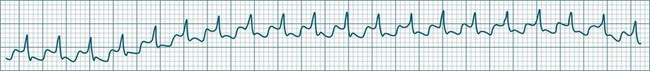
Accelerated Idioventricular Rhythm
Accelerated idioventricular rhythm (AIVR) has assumed a special place in cardiology because of its relatively common appearance during postinfarction reperfusion, thus often indicating successful revascularisation following PCI or thrombolytic therapy.20,21 It may therefore imply therapeutic success rather than mishap, and usually needs no treatment. The arrhythmia is commonly due to increased automaticity and as with other automaticity arrhythmias may show a ‘warm-up’ in rate, i.e. it may commence and then gradually accelerate and settle at a faster rate. This behaviour can be useful in differentiating arrhythmias from reentry which typically have an abrupt change in rate as their onset. When it occurs outside of the context of reperfusion, AIVR should be regarded as inappropriate ventricular excitation (Figure 11.17).
Atrioventricular Conduction Disturbances
Atrioventricular conduction disturbances make their appearance as delayed or blocked conduction from atria to ventricles, and thus appear as altered P–QRS (or P–R) relationships. The conventional classifications for AV block are based purely on the patterns of conduction. The classification as first-, second- and third-degree partially represents the severity of AV node or His-bundle dysfunction.7,9 AV block may complicate heart disease but is also seen commonly with drug therapy (e.g. digitalis, calcium channel blockers, beta-blockers and other antiarrhythmics).20 It may occur abruptly following vagal stimulation. When accompanying myocardial infarction, it is more likely to be transient following inferior infarction; whereas its appearance following anterior infarction is more likely to be permanent.
Degrees of Atrioventricular Block
First-degree AV block
All atrial impulses are conducted to the ventricles but conduction occurs slowly, with a P-R-interval >0.20 sec. 1 : 1 AV conduction is maintained (see Figure 11.18).
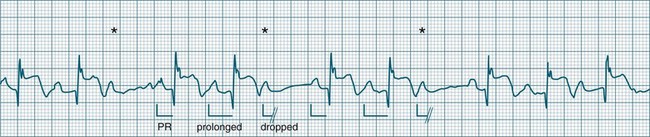
Second-degree AV block
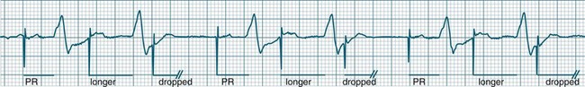
• Second-degree AV block type I (Wenckebach): A cyclical pattern of AV conduction is seen in which the conducted P waves show a progressive lengthening of the P–R interval until one fails altogether to be conducted (blocked, or dropped, P waves). Cycles begin with a normal or (often) prolonged P–R interval, which then extends over succeeding beats until there is a dropped beat. After the dropped beat the cycle recurs, commencing with a P–R interval equivalent to that commencing previous cycles63 (Figure 11.19). The frequency of dropped beats partially represents the severity of AV block. When, for example, every fifth P wave is not conducted, 5 : 4 conduction is said to be present. If AV conduction deteriorates further, more frequent P waves fail to be conducted (4 : 3, 3 : 2 conduction).
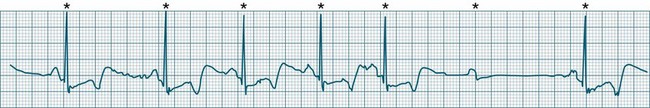
• Second-degree AV block Mobitz type II: Dropped beats (non-conducted P waves) are also present, but the conducted beats show a uniform P–R interval rather than any progressive lengthening9 (Figure 11.20). The dropping of beats may be regular, e.g. every fourth P wave (termed 4 : 1 block), progressing to 3 : 1, or even 2 : 1 block as AV nodal, or more commonly, His-Bundle conduction, worsens. Alternatively, the dropping of beats may be more irregular (variable block), with combinations of 2 : 1, 3 : 1, 4 : 1 or other levels of block evident in a given strip. The more frequent the dropped beats, the slower the ventricular rate and the greater the likelihood of symptoms. Second-degree Type II AV block is often associated with intraventricular conduction delay, with corresponding widening of QRS complexes. When this is seen it represents conduction impairment not just of the AV node but of intraventricular conduction as well. Progression to complete AV block is more common.9
A final form of second-degree block is ‘high-degree’ AV block, in which conducted P waves show a uniform P–R interval but, rather than single periodic dropped beats, multiple consecutive non-conducted P waves can be seen (Figure 11.21).
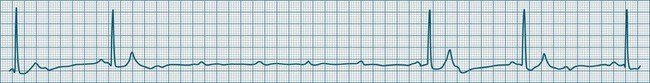
Third-degree (complete) AV block
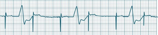
None of the atrial impulses are conducted to the ventricles, resulting in a loss of any relationship between P waves and QRS complexes (AV dissociation). Usually a lower pacemaker assumes control of the ventricular rate, and this focus may be either junctional (narrow QRS, at a rate of 40–60/min) or ventricular (wide QRS, at a rate of 20–40/min) (Figure 11.22).9
Nursing Management During AV Block
AV block may be progressive in nature, and may worsen with advancing heart disease or after introduction, or dose modification of drugs that depress AV conduction.23,24 Thus monitoring should include P–R interval measurement, and where the P–R interval becomes prolonged there should be an increase in vigilance directed towards further prolongation or the development of dropped beats, to signify advancing AV block. Treatment of AV block and bradycardia includes immediate assessment of cardiovascular status or other symptoms, including chest pain, dyspnoea, conscious state and nausea. The cause should be identified and treated where possible. Patients need to be on rest in bed, provided with reassurance and oxygen by mask or nasal prongs. If the patient is hypotensive, IV fluids should be administered and the patient laid flat. Standardised protocols for bradycardia should be applied if the patient is symptomatic, and these usually include:18
• atropine sulphate 0.5–1.0 mg IV25
• isoprenaline hydrochloride in 20–40 mcg increments,26 with an infusion at 1–10 mcg/min
If the patient is pulseless or unconscious, standard advanced life support should be administered (see Chapter 24). Persistent or recurrent symptomatic bradycardia or AV block may require permanent pacemaker implantation.18,19
Ventricular Arrhythmias
Ventricular ectopic rhythms may either occur as a response to slowing of the dominant cardiac rhythm (escape beats or escape rhythms) or may emerge at faster rates than the dominant rhythm (as premature ectopic beats, couplets, or ‘runs’ of ventricular tachycardia).9 Escape rhythms (occurring after a pause) should be regarded as physiological, as they protect against otherwise severe bradycardia (see Figure 11.16), whereas premature beats and rapid ventricular ectopic rhythms (occurring in advance of the dominant rhythm) occur when pathology gives rise to increased automaticity or reentry behaviour (Figure 11.23).7,9 Single ectopic beats may be benign occurrences, often seen in the absence of heart disease. However, their new appearance accompanying cardiac or systemic disease may precede the development of more serious arrhythmias, such as ventricular tachycardia or fibrillation, and thus warrant close monitoring. Ectopic beats, whether premature or late (escape), show characteristic features as follows:
• QRS complexes are wide (>0.12 sec) and of different morphology (large and bizarre in shape)27
• Notching of the QRS is common.
• ST segments and T waves are usually in the opposite direction to the major QRS deflection.

Ectopic beats may occur as single or coupled beats, or in runs of consecutive beats. Ventricular tachycardia is defined as greater than 3 consecutive ventricular beats occurring at a rate greater than 100/min.5
Causes of ventricular tachyarrhythmias include:3,8,28
• myocardial ischaemia, infarction
• cardiomyopathies/cardiac failure
• biochemistry: hypokalaemia, hypomagnesaemia, pH derangements
• adrenaline, isoprenaline, dobutamine, dopamine, levosimendan, atropine.
Patterns of Ectopy
Some patterns of ectopic frequency and morphology may warn of increasing risk for the development of serious arrhythmias such as ventricular tachycardia or fibrillation, and therefore earn a particular mention in monitoring. Historically, ectopic patterns have been graded according to their pre-emptive risk of serious arrhythmia development or 2-year mortality.29 Studies undertaken in 2003 and 2005 did however call into question the predictive status of certain ‘high risk’ ectopic patterns (such as ‘R on T’ ectopy), instead postulating that other factors such as a patient’s underlying left ventricular function and level of autonomic responsiveness may play a more significant role in the generation of life threatening ventricular tachyarrhythmias, independent of the prior presence or pattern of ectopy present.30,31 However, in the critical care context it is reasonable to respond to certain patterns (as shown in Box 11.1) by investigating and managing potential contributing causes. If the patient can be seen to be advancing through stages of increased arrhythmic complexity consideration for antiarrhythmic therapy should be given.
Box 11.1
Patterns suggesting higher risk of arrhythmia
Ventricular Tachycardia
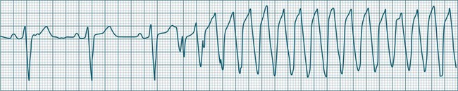
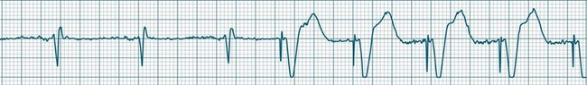
Ventricular tachycardia (VT) is described as a ‘run’ of three or more consecutive ventricular ectopic beats, at a rate greater than 100/min (Figure 11.24).12 The arrhythmia varies in its clinical impact, but when sustained is typically symptomatic with some degree of haemodynamic compromise. Ventricular tachycardia often presents as cardiac arrest, with the patient pulseless and unconscious, and is one of the major mechanisms of sudden cardiac death. The severity of symptoms depends partly on the rate (which may be 100–250/min), the duration of the arrhythmia, the presence of cardiac disease (ischaemic, congestive, hypertrophic, cardiomyopathic), and the presence of co-morbidities.9,32 When it develops, VT may be categorised as self-limiting (terminating without treatment), sustained for some period of time (minutes or longer), incessant (persisting until or despite treatment) or intermittent. Additional defining terminology includes monomorphic (all beats of the same morphology) or polymorphic (in which the rhythm conforms to the other features of VT but there is variability in the QRS shapes). ECG features of ventricular tachycardia:14,32,33
• Rate >100/min, rarely >240/min.
• Rhythm typically regular; there may be minor irregularity, especially on commencement and sometimes preceding self-termination.
• P waves may be absent. Atrial activity, whether dissociated or retrograde, is usually difficult to identify electrocardiographically.
• Morphology: QRS is wide (>0.12 sec). QRS often notched or bizarre in shape.
• Any axis is possible (normal axis, left or right axis deviation). An axis in the range of −90 to −180 degrees (‘no man’s land’) provides strong support for the diagnosis of ventricular tachycardia, as it implies the QRS originates at the apex and spreads through the ventricles upwards and to the right.
• ST segment and T wave displacement is in opposite direction to the major QRS direction.
If VT is not self-limiting, treatment depends on the severity of the symptoms. If the patient becomes pulseless and unconscious, advanced life support is initiated (see Chapter 24). If the patient is conscious and has a pulse, therapy can be undertaken more cautiously. Occasionally, robust coughing may revert VT in the cooperative patient. Antiarrhythmic therapy (at slower administration rates than during cardiac arrest) is usually undertaken first, along with biochemical normalisation. If unsuccessful, sedation and elective cardioversion may be necessary. Consideration for internal cardioverter defibrillator (ICD) implantation should be given to patients surviving ventricular tachycardia or fibrillation.34,35
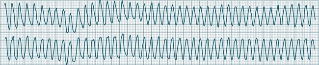
Ventricular Flutter
This uncommon arrhythmia is most likely just a subset of ventricular tachycardia, but because of its rapid rate (at times up to 300/min or more) and the appearance of QRS complexes that are largely indistinguishable from the T waves, ventricular flutter has earned its own classification.32 An example is shown in Figure 11.25. The diagnostic separation from other types of VT is clinically unimportant, and treatment should follow normal guidelines for VT.
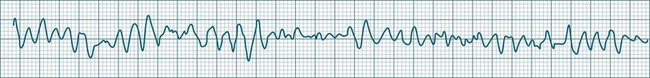
Ventricular Fibrillation
During ventricular fibrillation there is no recognisable QRS complex. Instead, there is an irregular and wholly disorganised undulation about the baseline.5,9 There are deflections, which at times approach rates of 300–500/min, but these are typically of low amplitude and none convincingly resemble QRS complexes (Figure 11.26). In the absence of organised QRS complexes the patient becomes immediately pulseless, and unconsciousness follows within seconds. Immediate defibrillation is required. If VF persists treatment occurs according to standing basic and advanced life support guidelines.
Polymorphic Ventricular Tachycardias
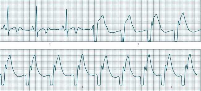
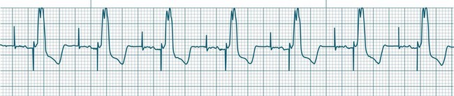
These forms of VT do not have a single QRS morphology. Rather, the QRS complexes during the rhythm vary from one shape to another, either alternating on a beat-to-beat basis or switching between groups of beats, with first one morphology and then another (bidirectional VT).9,32 The more common form of polymorphic VT is Torsades de Pointes (TdP), in which the QRS undergoes a gradual transition from one QRS pattern to another. The descriptive French term, literally ‘twisting of the points’, refers to the appearance of the ‘points’ (QRS direction), which is first positive and then negative, usually with an ill-defined transition between the two (Figure 11.27).28,36,37
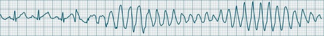
ECG features of Torsades de Pointes are:28,36,37
• QRS polymorphic, with the transitions between polarity as described above.
• rate often very rapid, in the range of 300/min.
• regularity: the evident complexes are often regular, but particularly within the transition between QRS directions there may be irregularity.
• often self-limiting but recurrent.
• Q–T prolongation evident during normal rhythm (see Research vignette)
• often precipitated by R-on-T ectopic beats.
• commonly pause-dependant, with bradycardia or single beat pauses precipitating onset.
Because of the very rapid rate, syncope and cardiac arrest are common, and advanced life support practices required. A thorough search for possible causes of Q–T prolongation should be undertaken. Causes include: class Ia (procainamide, quinidine, disopyramide) or class III (amiodarone, sotalol) antiarrhythmics,5,9 erythromycin, antidepressants, hypocalcaemia, hypokalaemia and hypomagnesaemia.32 Congenital long Q–T syndromes also exist.36 Apart from the general ventricular arrhythmia management principles listed below, the treatment of TdP includes cessation of Q–T prolonging agents, a greater emphasis on IV magnesium, and the use of isoprenaline and/or pacing to shorten the Q–T interval and prevent bradycardia.38
Bradycardia in patients with long QT requires special mention as Torsades de Pointes is so often bradycardia, or pause, dependent. Pauses prolong the QT and favour ectopy which more easily find the T wave, triggering TdP. The role of pacing and isoprenaline are to both prevent pauses, and to shorten the QT interval.36,39
Management of Ventricular Arrhythmias
The emergency management algorithm for life-threatening ventricular arrhythmias is described in the chapter on resuscitation. In general terms, the management of ventricular arrhythmias should include the following:38
• a search for and correction of causes, including
• immediate CPR and cardioversion/defibrillation for pulseless, unconscious ventricular arrhythmias (cardiac arrest).38 In conscious patients, initial treatment is usually pharmacological, and, if necessary, cardioversion is applied under the influence of short-acting anaesthetics (e.g. propofol)
• heart failure management, which needs to be aggressive if contributory
• electrophysiological (EP) testing, which should be performed for serious arrhythmias to identify foci or pathways and confirm effectiveness of treatment41
• implantable cardioverter defibrillator therapy, which should be considered for all survivors of sudden cardiac death,34,35 especially those with low ejection fraction and recurrent sustained ventricular arrhythmias41
• where a myocardial scar can be confirmed as the arrhythmic focus, surgical resection may sometimes be undertaken.
Antiarrhythmic Medications
Antiarrhythmic drugs are classified partly on the basis of beta-receptor or membrane channel activity, and partly by their physiological effects on the cardiac action potential. This is well represented by the Vaughan Williams classification system (see Table 11.1).39 However, as action potential abnormalities cannot be expediently identified at the bedside, matching antiarrhythmic agents to cellular physiology cannot realistically be undertaken. Instead, antiarrhythmics are chosen partly on the basis of their known efficacy, by their suitablity to atrial or ventricular arrhythmias, and after consideration of side effects and contraindications to known comorbidities in a given patient.41,42
| Class | Action | Drugs |
|---|---|---|
| IA | Sodium channel blockers: action potential prolongation | quinidine procainamide disopyramide |
| IB | Sodium channel blockers: accelerate repolarisation; shorten action potential duration | lignocaine mexiletine |
| IC | Potent sodium channel blockers: little effect on repolarisation | flecainide |
| II | Beta-blockers: depress automaticity (prolong phase 4); indirect prolongation phase 2 | metoprolol propanolol esmolol |
| III | Potassium (outward) channel blockers: prolong duration of action potential (prolonged repolarisation) | amiodarone sotalol (beta-blocker with class II actions) |
| IV | Calcium channel blockers | verapamil diltiazem |
Table 11.2 depicts the classification of the major acute antiarrhythmics in use in Australia and New Zealand, along with doses, arrhythmic indications, precautions and side effects. Class I agents all slow phase 1 (depolarisation) and so may slow down conduction and prolong the QRS. The subgroups of class I agents denote strength (A = weakest, C = strongest) and affect repolarisation, with class IA (prolonging), IB (shortening) and IC (not affecting) repolarisation duration. The class II agents (beta-blockers) depress automaticity, slowing the heart rate and prolonging the action potential. The class III agents notably prolong repolarisation, action potential duration and the Q–T interval. Class IV agents slow inward calcium channel flux, decreasing automaticity and prolonging the action potential.37
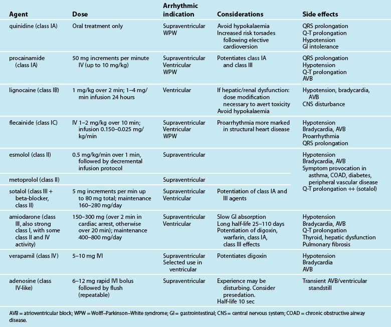
In the modern era, amiodarone ranks as the most effective agent in converting arrhythmias, but its use must be weighed against its considerable side effects.46,47 As with other class III drugs (e.g. sotalol) and class IA agents, there is a risk of Q–T interval prolongation and the development of Torsades de Pointes.41,48 Although sotalol carries the greatest risk of this arrhythmia, it may be selected when amiodarone side effects need to be avoided, or when combined antiarrhythmic–beta-blocker therapy is desired, (e.g. arrhythmias postinfarction or in the setting of heart failure). Lignocaine, the front-line ventricular antiarrhythmic for many years, lacks the efficacy of amiodarone, but is well tolerated and effective in the setting of the ischaemic myocardium.49 Whatever the choice of antiarrhythmic, additional attention should always be directed to biochemical correction, in particular serum magnesium, potassium and pH.38
Cardiac Pacing
Artificial cardiac pacing is most commonly used to provide protection against bradycardia and/or atrioventricular (AV) block. Slow heart rates can be sustained at more physiological rates by repetitive electrical stimulation, delivered by a pacemaker at a programmed rate. Temporary pacing may be provided as an emergency intervention, providing rhythm protection whilst reversible factors are overcome (biochemical or drug influence, myocardial ischaemia or infarction) or as support until confirmation of the need for permanent pacemaker implantation.50 Separate from such bradycardia protection, pacing may be undertaken to improve haemodynamic status, or to treat or suppress arrhythmias.
Principles of Pacing
A complete electrical circuit is achieved via a pacemaker connected in series with pacing leads to (and from) the myocardium. Electrical current is delivered to the heart via the negative electrode of the circuit, whilst the positive electrode completes the electrical circuit and enables sensing (detection) of the patient’s intrinsic cardiac rhythm.51,52 Electrical impulses of sufficient strength stimulate the myocardium to depolarise (and then to contract) at a rate selected by the operator.
Pacing leads (or pacing electrodes) may be positioned in contact with the endocardium via transvenous access, or attached to the epicardium when the heart is exposed at the time of cardiac surgery.53 For epicardial pacing, two separate leads or ‘wires’ are usually attached to each chamber paced, with one wire connected to each of the negative and positive terminals of the pulse generator (pacemaker). For transvenous pacing, a single lead is advanced to the apex of the right ventricle. These leads have a pacing electrode at their tip and a circumferential, or ‘ring’, sensing electrode slightly proximal to this. In an emergency, these transvenous ventricular pacing wires can be inserted promptly and at least establish a supportive ventricular rate.54 Temporary transvenous pacing is almost always undertaken for ventricular pacing only. While there are transvenous leads available for temporary atrial pacing, they are more difficult to position, and their use is very infrequent. By contrast, in the cardiac surgical patient, where direct lead attachment is straightforward, pacing may be undertaken as single chamber (atrial or ventricular) or dual chamber (atrial and ventricular).
Importantly, temporary transvenous wires are particularly vulnerable to movement.53 Unlike permanent pacing leads which are ‘fixed’ in some manner to the myocardium,55 temporary leads are simply blunt-ended leads which rely on lodging in muscular folds (trabeculae) near the apex to hold the lead in position. Activity limitation and strict rest in bed are therefore recommended for the pacemaker-dependent patient.
Major Pacemaker Controls
All devices give the operator control over pacing rate, pacemaker output (strength of the applied electrical stimulus), sensitivity (to intrinsic rhythm), and (in dual-chamber modes) the AV interval. Additional controls such as mode selection, output pulse width, upper tracking rate and the post ventricular atrial refractory period (for DDD mode) are available on some temporary and all permanent devices. Table 11.3 describes the major parameters that can be directly controlled on most temporary devices.
| Control | Function |
|---|---|
| Base rate | Sets the rate at which the pacemaker will discharge: pacing occurs at this rate unless the patient’s own rate is faster and is sensed by the pacemaker. Typically set at 60–100/min. |
| Ventricular output | The size, or strength, of the stimulus delivered to the ventricles. In temporary devices this is an adjustable current (measured in milliamperes [mA]). Output is increased until capture (successful stimulation) is achieved. The minimum current required to achieve capture is termed the output threshold. Impulses delivered below the threshold value will not capture the myocardium. Temporary pacemakers have an adjustable output range of 0.1–25 mA. |
| Atrial output | The size or strength of the stimulus delivered to the atria. Range 0.1 to 20 mA. |
| Atrial and ventricular pulse width | Not adjustable on all devices. Allows adjustment of the duration for which the pacemaker output is applied to the myocardium. Selectable range typically 1.0–2.0 milliseconds (msec) in 0.25 msec increments. Increasing the pulse width enhances ability to gain capture. |
| Atrioventricular delay | The interval between the delivery of the atrial and ventricular pacing stimuli. Normally this is set in the same range as normal P–R intervals (between 0.12 and 0.20 sec). |
| Sensitivity | Affects the ability of the pacemaker to detect the presence of spontaneous cardiac activity. Sensitivity settings can be adjusted between 1.0 and 20 millivolts (mV). Set at 1.0 mV the device is very sensitive (able to sense small electrical signals from the heart). Set at higher values, the device becomes less sensitive (higher voltage signals required to be detected), with the risk that QRS complexes or P waves will not be sensed. |
Pacing Terminology
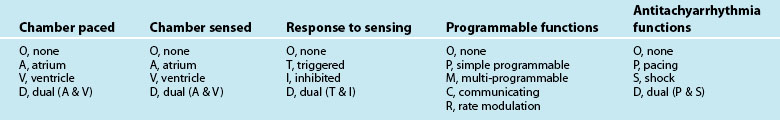
To aid in communication when discussing pacing functions, international agreement on terminology has been reached (see Table 11.4). A 5-letter code56 describes the pacing (and/or defibrillation) capabilities of any given device in terms of chambers involved in pacing, sensing, or other functions such as rate responsive pacing capabilities. A pacemaker designated as VVIR, for example, is capable of Ventricular Pacing, Sensing of Ventricular activity, Inhibiting pacing in response to sensing of ventricular activity, as well as possessing Rate responsiveness. While the first three positions in the terminology relate to all types of pacing, the fourth and fifth letters relate only to permanent pacing and have not been used through this chapter.
Capture
A ventricular pacing stimulus that successfully generates a QRS complex is said to have ‘captured’ the ventricles. The same applies when an atrial pacing stimulus ‘captures’ the atrium. It is important to verify that all of the stimuli cause capture. If pacing stimuli are not followed by a P wave or a QRS complex, ‘failure to capture’ is said to be occurring and requires immediate corrective action (see Figure 11.28).
Output and Threshold
The strength of the pacing stimulus applied is termed the pacing ‘output’, which is adjustable by the operator. On initiation of pacing, output is typically increased gradually until 100% capture is achieved. The minimum output required to achieve capture is termed the output threshold. Threshold may vary significantly with changes in biochemistry, arterial pH, myocardial perfusion, drugs and other factors.53,57–59 To accommodate potential threshold changes, output settings on the pulse generator are set with a ‘safety margin’, i.e. at least double the threshold value.58
Demand versus Asynchronous Pacing
Pacing can be configured in either demand (sensing), or asynchronous (non-sensing) modes.
Demand pacing
The most common approach to pacing are the so-called ‘demand’ modes. In these modes, pacing is provided only on demand: that is, when the heart rate falls below a nominated level (demand rate) (Figure 11.29). Demand pacing requires pacemaker detection of the patient’s intrinsic cardiac rhythm. If intrinsic rhythm is sensed, it ‘inhibits’ the pacemaker from delivering a pacing stimulus. The demand modes ensure that pacing is provided only when needed, and also protect against pacing during arrhythmically vulnerable moments in the cardiac cycle. Ventricular pacing delivered at the time of the T wave may induce ventricular tachyarrhythmias (Figure 11.30), whilst atrial pacing during atrial repolarisation (shortly after the P wave) may precipitate atrial tachyarrhythmias.60
Asynchronous pacing
Pacing may be delivered in an asynchronous mode, that is, without the capability of sensing the heart’s inherent activity. When in an asynchronous mode, the pulse generator will pace perpetually at the set rate, irrespective of whether the patient is generating his/her own rhythm. The main applications of non-sensing (asynchronous) modes are: (a) when there is oversensing, or risk of oversensing, such as in environments with strong electromagnetic fields; and (b) when patients would otherwise be asystolic or critically bradycardic if pacing were interrupted (pacemaker-dependent).51,61,62 In demand modes of pacing, false sensing of electromagnetic interference is able to inappropriately inhibit pacing, returning patients to their own unreliable rhythm. Temporary reprogramming to non-sensing modes (AOO, VOO, DOO) is commonly undertaken during surgery to prevent false pacemaker inhibition by electrocautery. For permanent pacing this is achieved by reprogramming, or by magnet application over the device, which causes asynchronous pacing at elevated rates (usually 90–100/min) only whilst the magnet is in place. The appropriateness of continuing in an asynchronous mode should always be reconsidered if the patient’s rate re-emerges in competition with the pacing due to the risk of arrhythmia.
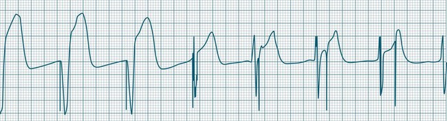
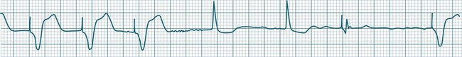
Ventricular Pacing
The delivered pacing stimulus should be followed immediately by a QRS complex which is wide (>0.12 sec) and often notched. Pacing from near the apex will produce an ECG which closely resembles left bundle branch block morphology, with left axis deviation. Repolarisation abnormalities are also seen, with ST segments and T waves displaced in the opposite direction to the major QRS direction in each lead.57
Ventricular pacing provides protection against bradycardia or AV block by stimulating the ventricles at a set (programmable) rate (Figure 11.31). Temporary, emergency, ventricular pacing may also be undertaken to prevent bradycardia-dependant tachyarrhythmias such as TdP.63 Pacing provides protection by both reducing the QT interval, as well as preventing pauses which give rise to ectopy and onset of TdP.63
Atrial Pacing
Atrial pacing alone is indicated when there is sinus node dysfunction in the presence of reliable AV conduction.50,62 The characteristic arrhythmias of such patients are symptomatic sinus bradycardia and/or sinus pause/arrest which may be syncopal. For atrial-only pacing to be undertaken, there needs to be confidence that AV conduction is intact, and that it will remain intact in the future64 as the annual incidence of progression to AV block is 1% in these patients.65 If there is AV block, atrial pacing alone is unsuitable, and dual-chamber pacing should be considered.50,62,64 The reliability of AV conduction is sometimes assessed by pacing the atria rapidly (e.g. at rates of up to 120 to 150/min). If AV block does not develop at these faster rates there can be confidence that AV conduction is reliable. The advantage of atrial pacing over ventricular pacing is the provision of atrial kick which may contribute substantially to cardiac output and blood pressure. In this respect atrial pacing is superior to ventricular pacing.
Atrial pacing tends to produce low-amplitude P waves, which vary from the typical P waves seen during sinus rhythm (Figure 11.32). They may at times be difficult to identify on the ECG. Appropriate lead selection is important to reveal the atrial depolarisation and confirm atrial capture. It is common for the AV interval (P–R interval) to extend slightly (e.g. to 0.20–0.22 sec) during atrial pacing compared with sinus rhythm, as the time taken for atrial impulses to traverse the atria from the pacing focus is longer than the sinus-to-AV node conduction interval.
Atrial Pacing and AV Block
Any degree of AV block is possible during atrial pacing and is rate dependent.64,65 Thus the severity of AV block may be worsened, not only by AV node dysfunction but also by changes in the atrial pacing rate. A patient with first-degree block may develop second-degree block if the atrial pacing rate is increased, without this implying worsening AV node function. Conversely, AV block developing during atrial pacing may be lessened or overcome by reducing the atrial pacing rate. An example of such rate-dependent AV block behaviour is demonstrated in Figures 11.33 to 11.35 which are sequential strips from the same patient.
Dual-Chamber Pacing
Pacing stimuli are delivered to the atria and ventricles at a selected rate. After delivery of the atrial stimulus there is a delay of usually 0.16–0.24 seconds (equivalent to a P–R interval) before delivery of the ventricular pacing stimulus (Figure 11.36). If the patient is able to conduct the atrial depolarisation to the ventricles themselves before the ventricular pacing is due, then the pacemaker senses the resultant QRS and inhibits ventricular pacing.
A dual-chamber pacemaker may demonstrate AV pacing at the set rate and the set AV delay as described above, or may operate as simply atrial pacing if normal AV node conduction occurs before the programmed AV delay has elapsed. Deliberately prolonging the programmed AV delay provides greater opportunity for patients to conduct to the ventricles by themselves. In some patients intrinsic ventricular conduction produces a contractile pattern which is superior to the contraction from ventricular pacing. This may result in better haemodynamics than when the ventricles are paced. There has been increasing interest in permitting native AV conduction because of these above reasons, and also on the basis of recent data from the DAVID trial which revealed that chronic ventricular pacing induces negative ventricular remodelling and worsening of heart failure.66 Prolonging AV delays to permit native conduction has become commonplace, but carries some slight arrhythmic risk67 (Figure 11.37).
DDD Pacing: The ‘Universal’ Pacing Mode
The introduction of the DDD mode of pacing added an important new dimension to dual-chamber pacing, that is, the ability to synchronise ventricular pacing to spontaneous atrial activity in patients with AV block.62 In addition to the normal bradycardia and AV block protection, the DDD mode features a ‘triggered’ function. If the pacemaker detects a P wave but a QRS does not follow within the preset AV interval (AV block), the pacemaker will be triggered to provide ventricular pacing at the end of the programmed AV interval. This means that the ventricular rate can be brought back under control of the sinus node, even though there is AV block. Consequently, in a DDD pacemaker it is common to see ventricular pacing at a range of different rates as it responds to sinus activity. This triggered behaviour of the DDD device is sometimes called ‘P-synchronous ventricular pacing’, although ‘atrial tracking’ is a more practical term as the ventricular pacing ‘tracks’ the atrial rate.
This triggering of ventricular pacing in response to sensed P waves is intended to mimic the behaviour of the AV node. It ensures that a QRS follows each P wave and brings the ventricular rate back under the control of the sinus node (see Figures 11.38 and 11.39). Pacing will be seen at a wide range of rates, as the ventricular pacing follows the normal speeding and slowing of the sinus rate in response to such conditions as pain, fever and activity. If the atrial rate exceeds the upper rate for tracking, then it is no longer possible for all of the atrial beats to be tracked. DDD pacemakers will start ‘dropping’ beats in a manner analagous to the behaviour of the AV node.
Complications of Pacing
Effective pacing may be disturbed by problems related to pacing leads, myocardial responsiveness, programmed values, the pulse generator itself (including power sources), and interactions between any of these factors.56–61 Four major disturbances to pacing are described below. These provide the bulk of pacing problems encountered, and because they may either interrupt pacing or precipitate serious arrhythmias, critical care nurses need to be competent in their recognition and management.
Failure to capture
The event in which pacing spikes do not successfully stimulate the heart is termed ‘failure to capture’. Pacing spikes are evident on the ECG but are not followed by either QRS complexes (in ventricular pacing) or P waves (in atrial pacing) (see Figures 11.40 and 11.41). Failure to capture may occur when the myocardial responsiveness (threshold) worsens, or when impulses do not reach responsive myocardium. Note that dislodgement of a lead from the myocardium will still show pacing spikes on the ECG as long as the lead is in contact with body fluids or tissue. Repositioning of leads must therefore be included in considerations during management.
Failure to capture may present as a clinical emergency and requires immediate attention. With failure to capture, patients are left to generate their own rhythm, which may be unacceptably slow. Failure to capture may be complete (all spikes not capturing) or intermittent (with only some spikes achieving capture). Even if there are only occasional spikes that fail to capture, immediate attention is required, as complete failure to capture may ensue (see Case Study at the end of this Chapter). Causes and management of failure to capture51,58,59,68,69 are listed in Table 11.5.
| Causes | Management |
|---|---|
Failure to Sense
Sensing of the intrinsic cardiac rhythm is necessary to achieve demand pacing. If rhythms are not sensed, then pacing will proceed at a fixed rate and in competition with the native rhythm (Figures 11.42 and 11.43). Pacing spikes delivered during the excitable period of the action potential may trigger tachyarrhythmias (see Figure 11.30). The risk of arrhythmias is greatest when ventricular pacing spikes are delivered just after the peak of the T wave, especially when there is myocardial ischaemia or infarction, or hypokalaemia. Immediate restoration of appropriate sensing needs to be undertaken. Causes and management of failure to sense60,68,70,71 are detailed in Box 11.2. Remember, however, that sensing controls are inverse: lowering numerical settings (e.g. from 5 to 2 mV) increases the sensitivity whilst increasing the value (from 1 to 4 mV) makes the pacemaker less sensitive.
Box 11.2 Failure to sense
Causes and management
• Sensitivity set too low (too high a number)
• Set in asynchronous mode (AOO, VOO or DOO)
• Increase sensitivity (to a lower number)
• Reverse the polarity of the electrodes if appropriate for the pacing wires (reverse connections of positive and negative electrodes)
• Increase the pacer rate to overdrive the competing rhythm
• If underlying rhythm satisfactory, consider turning pacemaker off
• Consider placement of an alternative sensing electrode (skin suture) to create unipolar pacing.
Failure to pace
Failure to pace is an imperfect term that is used to describe the event where the pacemaker does discharge but the impulse fails to reach the patient. In this sense it may be useful to regard failure to pace as resulting from an incomplete electrical circuit. The flashing pace indicators on temporary pacemakers confirm that pacing has occurred but the spikes fail to appear on the ECG. Most commonly, failure to pace is due to a loose connection in the lead system or a fractured lead or bridging cable. Electrocardiographically, failure to pace appears as failure of the pacing spikes to appear when expected. As with failure to capture, this leaves patients with whatever rhythm they can generate themselves, which may or may not be adequate. Failure to pace (also termed ‘failure to output’ in some literature) may present as complete loss of pacing, or just pacing at a slower rate than set (see Figures 11.44 and 11.45). If the patient’s rhythm is very slow, then failure to pace can be a clinical emergency. Even if there is an adequate rhythm, the situation requires immediate attention. Causes and management of failure to pace22,51,68–71 are detailed in Box 11.3.
Box 11.3 Failure to pace
Causes and management
• Disconnected lead/loose connections – commonest cause
• Pacemaker turned off or dysfunctional
• Fractured lead (may be internally fractured but outwardly intact)
Oversensing
Oversensing may result in momentary interruptions to pacing (pauses) or complete cessation of pacing. The clinical impact depends on the duration of oversensing, and on the patient’s ability to generate an underlying rhythm. Electromagnetic interference resulting in oversensing may arise from a variety of causes, originating from the patient (muscle movement) or external sources (devices). The sources of oversensing22,51,70,71 may be difficult to establish clinically but should be sought and corrected where able. Causes and management of oversensing are detailed in Box 11.4.
Box 11.4 Oversensing
Causes and management
An important distinction must be made between failure to pace and oversensing (see Figures 11.44 and 11.45). In both complications the pacing spikes do not appear when expected and may therefore be indistinguishable from each other. Clearly the management of the two complications is different, and so prompt, accurate differentiation is important to ensure appropriate management.
Nursing Practice
Nursing responsibilities in the care of the patient with a pacemaker include:
• pacemaker site inspection for inflammation/swelling/haematoma
• avoidance of hip flexion and rest in bed if femoral insertion
• vital signs, circulatory observations, etc. at intervals appropriate to the overall patient context
• confirmation of capture and sensing
• identification of return of spontaneous rhythm
• assessment of haemodynamic adequacy during both paced and spontaneous rhythms (BP, CO, perfusion, symptoms)
• strip documentation of rhythm 6-hourly and daily 12-lead ECG
• daily chest X-ray to confirm position of wire/absence of complications
• checking and tightening of all connections (leads to bridging cable, bridging cable to pulse generator) at commencement of shift and during all pacing adverse events
• confirmation of battery status each shift
• performance of pacemaker threshold assessment each shift or daily.
Protection Against Microshock
Patients with temporary pacemakers require microshock protection. Normally, small electrical stimuli (e.g. static electricity applied to the body) dissipate through body tissues and never reach sufficient current density at the heart to produce arrhythmias. However, pacing wires provide a direct route to the heart, so that even minor electrical sources may achieve sufficient current density at the heart to precipitate arrhythmias. Protection strategies include nursing patients in body- and cardiac-protected areas, insulating external connector pins when pacing is not in use, and using rubber gloves at all times when handling pacing wires.70
Pacemaker Function Testing
Routine pacemaker performance checks should be undertaken regularly in the patient with a temporary pacemaker. Temporary pacing leads and wires are prone to movement and therefore to sensing and capture threshold variation. Variations may also be marked when there is myocardial, biochemical and haemodynamic volatility as often seen in the critically ill patient. Pacemaker tests are performed to reveal the return of underlying rhythm which may be being concealed by pacing, and to measure thresholds for both capture and sensing, as these values typically change with time and in response to changing myocardial responsiveness.54,58,62,68 Regular checking allows detection of threshold changes, and setting of sensing and output safety margins, in order to minimise the development of acute failure to capture or failure to sense.
The practices employed to test temporary pacemakers vary widely across Australia, as do attitudes to whether this may or may not be undertaken by nurses. The sample protocol shown in Figure 11.46 provides an organised approach to testing during which safety has been emphasised. Because of the varying attitudes to nursing responsibilities, the use of this approach should be ratified at individual institutions before use.
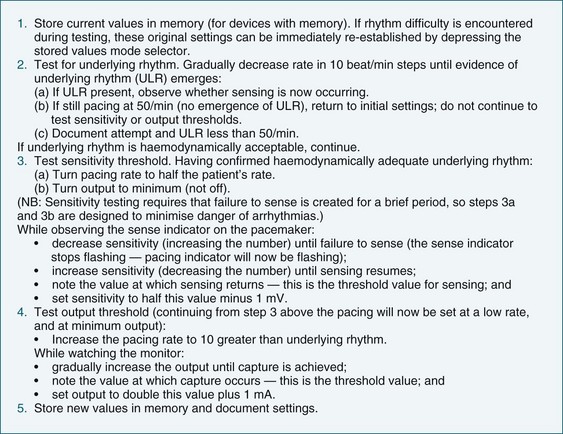
FIGURE 11.46 Routine temporary pacemaker testing protocol: underlying rhythm, output and sensitivity threshold test.
Testing pacemaker thresholds is performed daily or on each shift, but not if the patient is unstable, using the steps described in Figure 11.46. The test should be carried out promptly, with attention to avoiding undue bradycardia or periods of asynchronous pacing. The patient should be advised that pacemaker assessment is being undertaken and to report any sensations of lightheadedness, dyspnoea or other discomfort.
Pacemaker testing in the unstable pacemaker-dependent patient
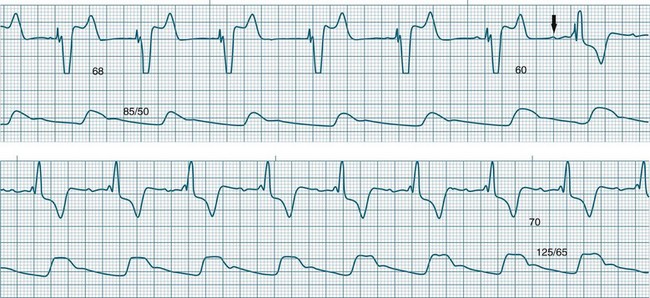
Greater caution must be applied in the testing of pacemaker functions if the patient has marked haemodynamic instability or has little or no underlying rhythm. It is common for pacemaker testing to be avoided altogether in such circumstances although this may be misguided. Routine testing of pacemaker function as described in Figure 11.46 may not be suitable, but testing for underlying rhythm, and some level of testing of capture threshold so as to be confident of safety margins is beneficial. For the patient with haemodynamic instability and/or inotrope use, testing for underlying rhythm becomes of even greater important as pacing may either prevent or conceal the return of sinus rhythm capability, and cardiac output may be as much as 50% greater with the atrial kick of sinus rhythm than during pacing (see Figure 11.47). It may take several seconds for the sinus node to ‘warm up’ and express itself, so decrease the rate gradually and only to reasonable levels (sinus rates of less than 50 are unlikely to be beneficial). Be sure to gain agreement from the multi-disciplinary team before undertaking testing in this context.
Permanent Pacing
For bradyarrhythmias which are not due to temporary, reversible factors, or are likely to be sustained or recurrent, permanent pacemaker implantation may be undertaken. Indications vary, but syncopal events, symptomatic bradycardia, pauses greater than 3 seconds, and bradycardia-dependent tachyarrhythmias are general indications for permanent pacing.63 Dual chamber pacing is usually provided27 unless the patient has chronic atrial fibrillation as it is not possible to capture the atria during fibrillation. For such patients rate responsive ventricular pacing (VVIR) is the most common mode.27,72 A dual chamber pacemaker may still sometimes be implanted if there is anticipation of possible future reversion of atrial fibrillation, and the device programmed to DDI or VVI in the interim. Alternatively the device may be implanted in DDD mode allowing the device to Automatically Mode Switch to DDI or VVI whilst the patient is in atrial fibrillation and then automatically switch back to DDD if atrial fibrillation reverts.
The most common mode of pacing with dual chamber devices is DDD, unless the patient has recurrent atrial tachyarrhythmias in which a non-tracking mode (e.g. DDI) may be selected.72,73 Patients with sinus node dysfunction are more likely to have rate responsive pacing enabled so that the pacemaker can adjust pacing rates to activity and exercise. Single chamber pacing of the atria only (AAI mode) is uncommon as it provides no protection against the future development of AV block.63
Permanent pacing leads differ from temporary pacing wires in that for chronic stability over a lifetime of activity the leads must be ‘fixed’ in some manner to the myocardium. ‘Active fixation’ leads have an extendable helix that is screwed into the myocardium at the time of implantation, much like a corkscrew. ‘Passive fixation’ leads by contrast are not directly secured to myocardium but have soft tines similar to the barbs of a spear, near the lead tip.55 The lead is positioned where these tines can embed within muscle infoldings (trabeculae) at the ventricular apex or in the right atrial appendage. Both types of leads have good chronic performance in terms of sensing and stimulation thresholds.55 However, an inflammatory response does develop at the lead–tissue interface and contributes to an increase in capture thresholds. This is most marked in the first month (acute threshold phase) during which the threshold may double or triple, before settling at a lower chronic threshold.55 Steroid-tipped leads are now universal and limit the local inflammatory response, reducing the magnitude of the acute threshold increase.55 Because of the expected threshold change during the first month or so, output safety margins need to be set more generously and patients are typically sent home with outputs set high (e.g. 3.5–5 Volts) even when thresholds at implantation may have been only 0.5–1 Volts. Chronic output settings will then be established at the first postoperative visit to the doctor in 6–8 weeks.37
Implantation Activities
Passage of leads into the heart during insertion may result in endocardial contact, causing AV block or bundle branch block. Therefore a femoral temporary pacing wire may be inserted before progressing to placement of the permanent pacing leads, particularly to ensure reliable ventricular rhythm during the insertion procedure. Historically, ventricular leads were implanted at the apex of the right ventricle, a position easily accessed and thought well tolerated. However recent trends have moved to ventricular lead placement in the right ventricular outflow tract (RVOT),66,73 to produce a more normal contractile pattern than from the apex and to prevent the ventricular remodelling seen in chronic RV apical pacing.66,73 Atrial lead insertion is most commonly at the right atrial appendage, i.e. in the roof of the right atrium. The atrial lead is passed down the superior vena cava into the right atrium and then steered back upwards to engage the atrial appendage. Both ventricular and atrial leads are tested for performance following placement. Leads are then secured within the pacemaker pocket and the pulse generator is attached to the leads and secured in the pocket. The pocket is closed and testing is repeated to confirm secure connections of the leads to the pacemaker. Device and lead testing is repeated on day 1, weeks 6–8 and then every 12 months to confirm operation.38
Pacemaker Parameters: Programming and Status Reports
Knowing how a patient’s pacemaker is programmed is crucial to interpreting pacemaker behaviour in the clinical setting. This has become increasingly important to enable determination of whether a change in behaviour is a problem or simply an automated behaviour. Device printouts are available whenever a device is interrogated or reprogrammed. The following section is a guide to how to interpret device printouts to access key information about pacemaker programming, highlighting some of the features of the modern permanent pacemaker, as well as some of the clinical and diagnostic value of the information provided. Device printouts contain an enormous amount of information, but of immediate importance are the summary pages that outline all of the operating parameters, active automated features, results from recent tests and battery status (see Figure 11.48 for an example). Important elements include:
• Patient/device details: patient name, type of device, date and time of the printout.
• Battery information: a bar graph displays the progress of the battery towards the Elective Replacement Indicator (ERI); the Magnet Rate (i.e. the rate that asynchronous pacing will occur at if a magnet is placed over the device); the longevity (indicating the minimum remaining longevity of the device if the patient was to be paced 100% of the time in the current settings).
• Current Parameters: basic pacemaker set up including base rate, maximum rate at which the atrial rhythm will be tracked, AV delay, output settings and pulse widths for both chambers.
• Episodes: summary of any arrhythmia episodes that have been recorded since the last interrogation, any Automatic Mode Switching events that have occurred.
• Events: an event in pacing terms is a beat, rather than a clinical event; every atrial beat (sensed or paced) and every ventricular beat (sensed or paced) is recorded allowing the calculation of the percentage of atrial and ventricular pacing since the last interrogation; this can be compared to previous reports to assess whether pacemaker dependence is increasing or decreasing.
• Test Results: the results of device and lead testing performed during the current interrogation as well as testing from the last session performed, including graphic trends of all tests over time shown in a separate section of the report.
• Sense Results: the results of the sensing tests carried out in the current interrogation, the last session’s values are also shown, and graphic trends of sensing over time can be viewed in a separate section of the report.
• Lead Impedance: the results of impedance measurements from the current interrogation and the last session; this provides information about the integrity of the pacing leads, connections, and their interface with the myocardium; impedance is the resistance to current provided by the electrical circuit. Variations in impedance may be seen if the pacing lead is being degraded, the pacing circuit is interrupted or not properly connected or the pacing lead becomes dislodged. Generally, measured impedances do not vary by more than 100 Ohms between sessions.
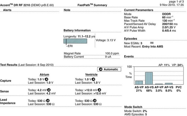
Cardiac Resynchronisation Therapy
Cardiac resynchronisation therapy (CRT) involves the use of pacing to improve the performance of the left ventricle in heart failure patients. Initially CRT was undertaken only in patients with severe heart failure (NYHA Class III–IV with ejection fraction <30%) due to dilated cardiomyopathy with left bundle branch block (LBBB)74,75 but its proven efficacy in all major randomised controlled studies76–80 has seen the range of indications expand to include patients with less severe heart failure (NYHA Class I and II).25 CRT is typically only undertaken after demonstrating failure to respond to optimal pharmacological therapy.
Optimum systolic performance requires all segments of the ventricles to contract more or less synchronously. However, in LBBB septal depolarisation occurs well in advance of the delayed conduction to the lateral left ventricular wall. The impact on contraction is to create ventricular dyssynchrony, with the septum contracting before the lateral wall, rather than synchronously with it. Similarly, ventricular relaxation becomes dyssynchronous which may lessen myocardial perfusion and limit ventricular filling, both of which can become contributors to the severity of heart failure.26 Whilst the majority of patients with LBBB have dyssnchrony and systolic dysfunction, the impact may not be of note for those with otherwise normal hearts, but becomes much more pronounced when there is existing myocardial disease and/or heart failure.26,81 With very wide LBBB (e.g. >0.14 sec) the impact is greater, as the dyssynchrony between the septal and free wall contraction is exaggerated.26,75,81,82
In CRT, pacing leads on both the right ventricular (RV) septum and the left ventricular (LV) lateral wall are used to stimulate both muscle masses at the same time, with the aim of improving heart failure in patients with significant dyssynchrony.83 LV and RV pacing stimuli may be delivered simultaneously, although programming of either LV or RV stimulation first by 10–80 msec is seen more often. The aim is that a reduction in QRS duration can be seen electrocardiographically, preferably with the QRS returning to normal duration (<0.12 sec).83 Expected outcomes of CRT include:76–8384
• improvement in NYHA functional class
• improvement in quality of life
• improvement in physical function
• improvement in ejection fraction and reduction in ventricular size
The right ventricular septal lead is implanted in standard fashion, positioned either at the RV apex or outflow tract. Most commonly the left ventricular lead is also positioned transvenously, with the lead advanced through the coronary sinus into a coronary vein on the lateral LV wall. In a minority of cases a separate mini-thoracotomy may be necessary for secure positioning of an epicardial LV lead. Two types of devices currently exist: CRT-P (Pacemaker) which is a pacemaker achieving resynchronisation, and CRT-D (Defibrillator) which adds resynchronisation to an implantable cardioverter defibrillator. These latter devices are implanted more commonly as the combination of severe heart failure and ventricular tachyarrhythmias is frequently present.85,86
Non Responders to CRT
Disappointingly, up to 25 % of patients who receive CRT devices fail to gain the expected benefits of improved heart function and are termed non-responders.78,80 Failure to respond may be due to device- or lead-related factors, or because of cardiac factors which contribute to worsening heart failure, especially myocardial ischaemia, atrial fibrillation84, and diminishing responses to adjunctive pharmacological therapy. It should be noted that the preference in CRT is to see paced ventricular rhythms rather than the patient’s own QRS complexes as pacing produces a synchronised contraction of the LV compared to the patient’s native, dyssynchronous contraction. The aim is for >90% of ventricular beats to be paced to achieve the desired benefit from CRT. Amongst device/lead-related factors are loss of capture by either the LV or RV lead, resulting effectively in loss of resynchronisation. Recognition of this can be difficult because loss of capture by only one of the ventricular leads will still appear as capture from the remaining ventricular lead (see below).
Optimisation of Device Programming
Device programming can have a significant impact on the benefit conferred by CRT and had historically been conducted under echocardiographic assessment of the impact on ventricular filling and contraction. It is not practical for all patients to undergo regular echocardiography and so alternative approaches to optimisation are being developed. The critical timing factors which should be optimised are the atrioventricular (AV) delay and the delay between stimulation of the left and right ventricles (V–V delay). Recent developments allow ‘electronic optimisation’ whereby CRT devices themselves can calculate optimum settings based on automated measurements of intracardiac events87,88, but are not available on all devices. The impact of effective optimisation may be sufficient to convert non-responders to responders.
Recognising Failure to Capture in a CRT device
Recognising failure to capture in CRT is made difficult by the fact that both ventricles are paced. The loss of pacing spikes followed by QRS complexes will only occur if there is failure to capture from both the LV lead and the RV lead.88 The ECG during failure to capture by just the LV lead will still show capture from the RV lead. Instead of loss of the QRS, to identify loss of capture it is necessary to look more closely at QRS morphology and vectors to confirm capture or loss of capture from either the left or right ventricular lead.88 A 12-lead ECG is helpful, but if not available, lead V1 (or MCL1) and lead I are the most helpful in confirming RV, LV or Bi-ventricular (Bi-V) capture. Specific changes include:
• RV capture only: the QRS will be wide (>0.12 sec) with left axis deviation, lead V1 (or MCL1) will be a negative complex, most commonly as a QS complex, QRS in lead I will be upright, as an R wave or sometimes rSR (see Figure 11.49)
• LV capture only: the QRS will be wide (>0.12 sec) with right axis deviation, lead V1 (or MCL1) will be an upright complex, either as an R wave, or less commonly as an rSR, QRS in Lead I will be a negative complex, either as a QS or rS complex (see Figure 11.49).
• Bi-Ventricular capture: the ECG is less predictable depending upon the timing of the left and right ventricular stimuli. If LV stimulation occurs well ahead of RV then the ECG will look more like LV capture only, whereas if RV stimulation occurs well ahead of LV then the ECG will look more like RV capture only. Nevertheless, the expectation is that when both leads are capturing the QRS will become narrower (usually <0.12 sec)84 and the axis is either reasonably normal or may be deviated leftward or rightward. Morphologies are usually somewhere between those seen with RV-only or LV-only pacing. A uniform ECG pattern cannot be described, but in a given patient there should be consistency between their ECGs (see Figure 11.49).
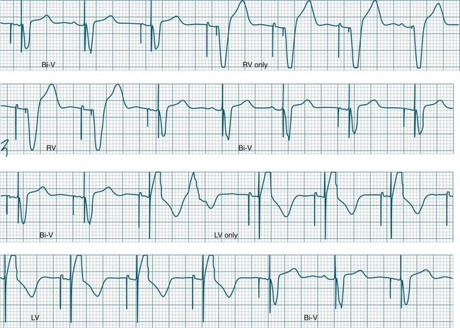
Cardioversion
Electrical cardioversion can be applied as an alternative or adjunct to pharmacological therapy in the management of tachyarrhythmias. By far the most common cause of tachyarrhythmias is reentry, in which current can continue to circulate through the heart because of different rates of conduction and recovery in different areas of the heart (temporal dispersion). Conduction through reentry circuits can continue as long as the circulating stimulus encounters non-refractory tissue. The aim of cardioversion is to excite all myocardial cells at the same time with the result that all of the heart will also be refractory at the same time. If this is achieved, the circulating stimulus dies out for lack of non-refractory tissue to conduct through. If the applied shock does not depolarise the greater bulk of myocardium, then non-depolarised cells are still available for conduction and the arrhythmia may persist. External shocks of 100–200 Joules (biphasic) are required for sufficient current density to reach the myocardium and depolarise the greater bulk of cells, thus extinguishing available pathways.89 Drugs or biochemical correction may be necessary to prevent recurrence. Success rates from cardioversion range from 70–95% depending on the rhythm.89 Arrhythmias due to increased automaticity are less amenable to cardioversion, as there is a high chance of early arrhythmia recurrence; and for arrhythmias occurring as a complication of digitalis toxicity, cardioversion (but not defibrillation) is contraindicated.89
Early defibrillation increases survival from ventricular fibrillation. The success of public-access defibrillator schemes (in airports, shopping and sporting venues) has warranted their increased availability.90 Automatic external defibrillators (AEDs) in the home or community simplify the task of applying defibrillation by non-healthcare responders and increase access to definitive electrical management for patients suffering ventricular arrhythmias. For patients who have survived previous arrhythmic cardiac arrest, immediate cardioversion or defibrillation at any time or location may be necessary. Such patients may require an implantable cardioverter defibrillator. Emergency defibrillation, biphasic and monophasic waveforms, electrical principles and equipment management are discussed more completely in Chapter 24.
Elective Cardioversion
Elective direct current reversion (DCR, or cardioversion) applied under short-acting sedation or anaesthesia is undertaken for non-cardiac arrest arrhythmias.90 These include atrial fibrillation, tachycardia or flutter, conscious ventricular tachycardia, AV nodal reentry tachycardia, and conscious tachyarrhythmias complicating Wolff–Parkinson–White syndrome. The time available for preparation is variable and depends on the haemodynamic impact of the arrhythmia. Patients admitted for reversion of atrial fibrillation or flutter may be stable throughout their hospitalisation, whereas patients with conscious VT may initially demonstrate stability, only to decompensate later without warning.
When time permits the patient should be thoroughly investigated, including physical examination, neurological assessment, palpation of peripheral pulses, electrocardiograph, biochemistry, and serum drug levels where necessary. Fasting should be ensured where possible.91 If atrial fibrillation is present transthoracic echocardiography is undertaken to rule out atrial thrombus, as restoration of atrial contraction may cause pulmonary or systemic arterial embolisation. The patient should be fully informed of the rationale for and nature of the procedure and have all necessary preparatory tasks explained to them.
After the procedure the patient should be closely monitored for return to wakefulness, airway protection capability, effective respiration and gas exchange, rhythm stability, blood pressure, and for any changes in neurological status or peripheral pulses. Pain and inflammation at cardioversion discharge sites may be lessened by application of topical ibuprofen 5% cream 2 hours before elective DCR, where this is feasible.92 Energy requirements for reversion of atrial tachycardia or flutter may be as little as to 50 J.93 The 2010 recommendations of the European Resuscitation Council are for initial shocks at 70–120 J (biphasic) for atrial flutter, and 120–150 J for cardioversion of atrial fibrillation and ventricular tachycardia.46 In any of the arrhythmias, if initial shocks are unsuccessful, repeat attempts at higher energy settings (up to 360 J) may be undertaken. Prior to discharge, patients and their families should be informed of the potential for post-procedural chest wall discomfort and topical and oral analgesic advice provided. Relevant contact information in the event of redevelopment of arrhythmia symptoms or other health concerns should also be provided.
Implantable Cardioverter Defibrillators
Implantable cardioverter defibrillators (ICDs) may be implanted for survivors of sudden cardiac death (SCD) or haemodynamically significant, potentially lethal, ventricular arrhythmias.94 They have been repeatedly demonstrated in large clinical trials to provide significantly improved survival compared with conventional or pharmacological treatment.95–97 This ‘secondary prevention’ application of ICDs dominated the early indications for devices, with trial meta analysis demonstrating a mean 27% mortality reduction compared to antiarrhythmics.98 However, more recently indications have expanded to ‘primary prevention’ in patients without prior cardiac arrest, as it has become clear that heart failure patients with ejection fractions <30% (including both ischaemic and non-ischaemic cardiomyopathies) have a high risk of sudden cardiac death due to ventricular arrhythmias, including patients with and without non sustained VT.99,100 In these contexts patients may receive pure ICDs, or ICDs coupled with cardiac resynchronisation therapy capabilities to also combat their heart failure (CRT-D devices).
All modern ICDs provide biphasic shock waveforms only. Arrhythmia detection and classification usually requires only a few seconds, and charging to maximum joules in a new device takes up to 10 seconds. As the battery declines charge time may increase to 15–20 seconds or longer. Maximum energy delivery capabilities vary between manufacturers but are all in the range of 30–40 J. Typically, shocks for ventricular fibrillation are provided at the maximum available capability of the device, but for ventricular tachycardia, lower ‘cardioversion’ shocks may be attempted first (e.g. 15–25 J). If initial shocks are unsuccessful, devices are usually programmed to increase to maximum joules for subsequent shocks.94
Defibrillation thresholds may be measured at the time of implantation of the ICD. It is desirable that a 10 J safety margin exists, i.e. for a device that can deliver 30 J, it is preferred that successful defibrillation can be achieved at 20 J or less so that there can be confidence that the device will revert clinical arrhythmias, and to cover any threshold increases in the future.101 Intraoperative defibrillation testing has become less common with time, partly because of risks associated with inducing ventricular fibrillation, and partly because of evidence that clinical fibrillation has different characteristics to induced fibrillation.102 However, VF induction and defibrillation testing remains the only way to demonstrate whether a device has successfully interrupted VF. If testing is to be performed the patient is prepared for external defibrillation with all safety precautions and subsequent care as outlined above in the section on cardioversion.
ICDs are usually programmed to deliver up to six ‘therapies’ during a tachyarrhythmia episode. For VF, this usually means six attempts at defibrillation at maximum joules and then further antitachycardia therapies are aborted. No more shocks will be delivered. Antibradycardia pacing operation will continue. If the tachyarrhythmia is interrupted at any point and then recurs, the 6-therapy counter will recommence. For ventricular tachycardia, attempts may first be made to overdrive pace. So-called antitachycardia pacing (ATP) aims to interrupt VT by pacing the ventricles slightly faster than the VT rate so as to interrupt reentry, the major cause of VT (see Figure 11.50 for example of reversion). A number of attempts at ATP may be programmed, often with each at slightly more aggressive rates at each successive attempt. This is especially true if the patient is known to tolerate their VT reasonably well. Persistence of VT after ATP will see the device attempt first low energy cardioversion (15–25 J) and then progress to 30–40 J if unsuccessful. The same limit of six therapies usually applies for an episode.
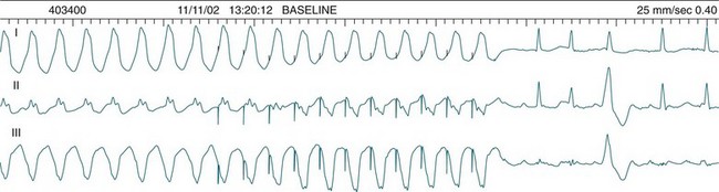
Tachyarrhythmia Detection and Classification
ICDs are configured to classify and treat arrhythmias first on the basis of rate. Defibrillation algorithms using high-energy settings (30–40 J) are followed when the rate is very fast (e.g. >200/min), as syncope is likely even if the rhythm is not ventricular fibrillation (e.g. very fast VT). At slower rates, other antitachycardia options may first be attempted as described above. Additionally, at slower rates of tachycardia, attempts are made to discriminate between ventricular and supraventricular (including sinus) tachycardias (SVTs) using a variety of criteria, as shown in Figure 11.51. SVT discrimination by a device is similar to criteria a clinician would use when deciding between VT and SVT and includes regularity or irregularity of the rhythm, sudden or gradual onset, similar or different morphology to the previous sinus rhythm and atrioventricular relationships. If these discriminators indicate that a tachyarrhythmia is supraventricular, then therapy can be withheld, avoiding inappropriate therapy. The major device capabilities and programming options of an ICD are shown in Figure 11.51.
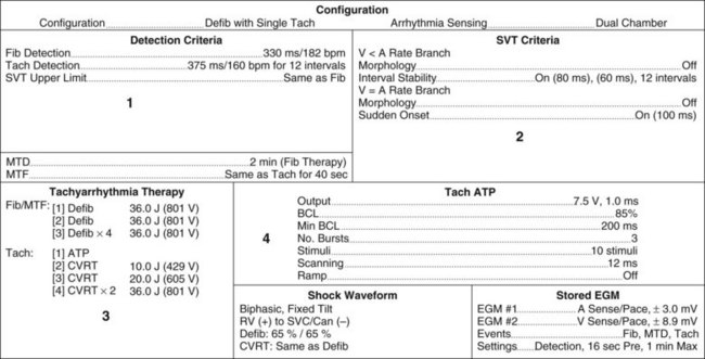
Patients receiving ICDs require particular education and support, as the experience of shocks can be painful and disturbing and the anticipation of shocks is a cause of anxiety and/or depression.70,103 This is especially true of shocks delivered to the conscious patient. Inappropriate therapy delivery remains a significant problem, and as many as 25% of ICD therapies have been reported as inappropriate, delivered due either to supraventricular arrhythmias or oversensing of electromagnetic interference.103,104 The avoidance of strong electrical fields (welding, magnetic resonance imaging, generators) should be stressed, as well as direct contact with devices such as TENS machines or electrocautery devices.70 If surgery requiring diathermy becomes necessary, antitachycardia therapies are usually programmed to OFF to avoid inappropriate detection and treatment.
Patients should be encouraged to rest after any therapy delivery, and where multiple or inappropriate discharges occur they should report to a healthcare facility for assessment.105 If repeated inappropriate therapy continues, it may be suspended by the placement of a ring magnet over the device.70 This suspends the antitachycardia features of the device while the magnet is in place – no therapy will be delivered by the device. Removal of the magnet will immediately reactivate antitachycardia therapies. Back-up (antibradycardia) pacing functions remain active and unaffected during magnet application.
In the event of unsuccessful reversion of a ventricular arrhythmia by ICD therapy, standard advanced life support protocols should be applied. External defibrillation can be undertaken with paddles in normal positions, taking care to avoid positioning paddles over the ICD.105 External chest compressions can safely be undertaken by rescuers, including during device therapy.70
Ablation
Ablation therapies are aimed at destroying tissues that (a) generate or sustain haemodynamically significant or potentially lethal arrhythmias (arrhythmic foci or reentry pathways), or (b) permit uncontrollable atrial arrhythmias to conduct at rapid rates to the ventricles (the accessory pathways of the Wolff–Parkinson–White syndrome, or at times the AV node itself).106 Tissue destruction is achieved by the application of radiofrequency (RF) energy to very localised areas of the endocardium, which results in excessive tissue heating, cellular damage and eventual tissue death.106 Unlike preventive or episode-terminating pharmacological or electrical arrhythmia therapies, successful ablation is curative and can therefore spare patients a lifetime of careful medication compliance, self-monitoring for complications, and living under the uncertainty of arrhythmic threat and/or the delivery of therapy from an implantable cardioverter defibrillator.
For arrhythmia ablation, electrophysiological studies are undertaken to closely map the location of abnormal foci, reentry circuits or accessory pathways, and radiofrequency catheters are then guided to these sites to deliver therapy. The search for arrhythmic sites may take some time, but studies are well tolerated as long as patients can remain supine for the sometimes extended periods. The application of radiofrequency and the consequent tissue injury is painless in most cases.105,106
Success rates for ablation therapies have been reported at 82–92% for accessory pathway ablation (depending on pathway location), 90–96% for AV nodal reentry tachycardia, and 75% for atrial tachycardia and flutter.107 Complication rates, mostly AV block, have been reported at 2.1–4.4%, with procedure-related mortality below 0.2%.106,108 When applied to patients with ideopathic ventricular tachycardia, procedural success has been reported at 85–100%.108 Complications, including death from ventricular wall perforation,107 have occurred, but major complication rates of less than 1% are generally seen.108
For ablation of ventricular tachycardia, it is necessary to first perform pace mapping to locate the focus. Endocardial pacing is applied from many sites until a paced rhythm with the same 12-lead ECG morphology as the ventricular tachycardia is achieved. This confirms the focus, thus identifying the location(s) to which radio freqency needs to be applied. Generally, ablation is undertaken for monomorphic VT only.106
Summary
Case study
A 63-year-old woman was admitted to intensive care at 12 : 28 on a Friday afternoon following Aortic Valve Replacement. Surgery was uneventful, however, post-operative asystole required placement of two atrial and two ventricular epicardial pacing wires. Six minutes after admission the following rhythm, as seen in Figure 11.52, was observed.
• Initial pacemaker settings: DDD mode; Rate 80/min; AV delay 160 ms
• Atrial output: 20 mA (maximum) with atrial pulse width @ 1 ms
• Ventricular output: 18 mA (maximum 20 mA) with ventricular pulse width @ 1 ms
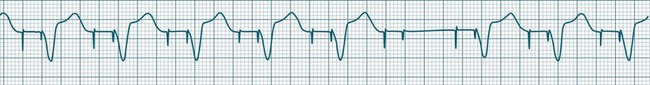
• The patient was known to have underlying asystole. Failure to capture, even on a single beat, could progress to complete loss of capture.
• The ventricular output was already at 18 mA and still losing capture. An adequate safety margin could not be provided, and there was very little scope for increasing output if failure to capture recurred (maximum output 20 mA on this device).
• Atrial output was already at maximum (20 mA) and not capturing.
• It was Friday afternoon. Ideal resources were available now, but this would change soon, with the resource limitations that night duty or weekend staffing pose.
• Simultaneous atrial and ventricular failure to capture could point to a severe systemic abnormality requiring investigation and management.
Events and treatment steps that followed included:
• Ventricular output was increased to 20 mA but single beat failure to capture continued intermittently (every 20–30 sec). Whilst seeking medical agreement for atropine administration, the following, as shown in Figure 11.53, occurred (12 : 38 hours).
• Intravenous Atropine Sulphate 1.0 mg was administered with prompt restoration of 1 : 1 ventricular (but not atrial) capture.
• Biochemistry and arterial blood gases were normal.
• After 7 minutes of 1 : 1 capture, intermittent single-beat failure to capture recommenced and at 12 : 46, capture again deteriorated and Figure 11.54 was recorded.
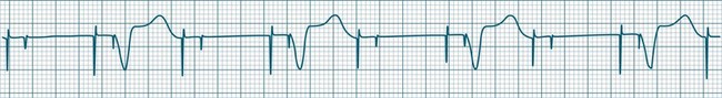
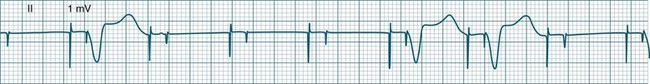
Learning activities
1. List the major ECG criteria for each of the major arrhythmias described in this chapter
2. Describe the general approaches to management of bradyarrhythmias, tachyarrhythmias and AV block
3. Describe the ECG features which would allow differentiation of the various supraventricular and atrial arrhythmias.
4. Discuss the antiarrhythmic therapies available for the treatment of atrial and ventricular arrhythmias.
5. Describe the indications, mechanisms of action, dose and side effect of the major antiarrhythmics in classes I – IV.
European Heart Rhythm Association (EHRA). http://www.escardio.org/communities/EHRA/Pages/welcome.aspx.
European Resuscitation Council. https://www.erc.edu/index.php/mainpage/en/ECG.
ECG quizzes and teaching materials. http://library.med.utah.edu/kw/ecg/.
Arrhythmia and cardiac device presentations, manuals, and learning resources. http://www.hrsonline.org/.
1 Novak B, Filer L, Hatchett R. The applied anatomy and physiology of the cardiovascular system. In: Hatchett R, Thompson D. Cardiac nursing: a comprehensive guide. Philadelphia: Churchill Livingstone Elsevier, 2002.
2 Guyton A. Textbook of medical physiology, 8th edn. Philadelphia: WB Saunders; 1991.
3 Rubart M, Zipes DP. Genesis of cardiac arrhythmias: Electrophysiologic considerations. Braunwald E, Zipes DP, Libby P. Heart disease:a textbook of cardiovascular medicine, 6th edn, Philadelphia: WB Saunders, 2001.
4 Waldo AL, Wit AL. Mechanisms of cardiac arrhythmias and conduction disturbances. Alexander RW, Schlant RC, Fuster V. Hurst’s The Heart Arteries and Veins, 9th edn, New York: McGraw-Hill, 1998.
5 Conover MB. Understanding electrocardiography, 7th edn. St Louis: Mosby; 1996.
6 Mines GR. On dynamic equilibrium in the heart. J Physiol. 1913;46:349.
7 Dunn MI, Lipman BS. Lipmann-Massie clinical electrocardiography, 8th edn. Chicago: Year Book Medical; 1989.
8 Josephson ME. Clinical cardiac electrophysiology. Philadelphia: Lippincott, Williams & Wilkins; 2002.
9 Wagner GS, Marriott HJL. Marriott’s practical electrocardiography, 10th edn. Baltimore: Lippincott, Williams & Wilkins; 2000.
10 Chen-Scarabelli C. Supraventricular arrhythmias: an electrophysiology primer. Prog Cardiovasc Nurs. 2005;20(1):24–31.
11 McCord J, Borzak S. Multifocal atrial tachycardia. Chest. 1998;113(1):203–209.
12 Heeringa J, van der Kuip D, Hofman A, Kors JA, van Herpen G, et al. Prevalence, incidence and lifetime risk of atrial fibrillation: the Rotterdam study. Euro Heart J. 2006;27:949–953.
13 Maglana MP, Kam RM, Teo WS. The differential diagnosis of supraventricular tachycardia using clinical and electrocardiographic features. Ann Acad Med Singapore. 2000;29(5):653–657.
14 Haghi D, Schumacher B. Current management of symptomatic atrial fibrillation. Am J Cardiovasc Drugs. 2001;1(2):127–139.
15 Naccarelli GV, Wolbrette DL, Khan M, Batta L, Khan M, et al. Old and new antiarrhythmic drugs for converting and maintaining sinus rhythm in atrial fibrillation: comparative efficacy and results of trials. Am J Cardiol. 2003;91(6A):15D–26D. 20
16 Shah D. Catheter ablation for atrial fibrillation: mechanism-based curative treatment. Exp Rev Cardiovasc Ther. 2004;2(6):925–933.
17 Schuchert A. Contributions of permanent cardiac pacing in the treatment of atrial fibrillation. Europace. 2004;5(Suppl1):S36–S41.
18 Kaushik V, Leon AR, Forrester JS, Jr., Trohman RG. Bradyarrhythmias, temporary and permanent pacing. Crit Care Med. 2000;28(10Suppl):N121–N128.
19 Corcoran SJ, Pressley L. The slow pulse: is a pacemaker necessary? Med J Aust. 1999;170(11):556–561.
20 Ilia R, Amit G, Cafri C, Gilutz H, Abu-Ful A, et al. Reperfusion arrhythmias during coronary angioplasty for acute myocardial infarction predict ST-segment resolution. Coron Artery Dis. 2003;14(6):439–441.
21 Bonnemeier H, Ortak J, Wiegand UK, Eberhardt F, Bode F, et al. Accelerated idioventricular rhythm in the post-thrombolytic era: incidence, prognostic implications, and modulating mechanisms after direct percutaneous coronary intervention. Ann Noninvas Electrocardiol. 2005;10(2):179–187.
22 Hales M. Keep up the pace: the prevention, identification and management of common temporary epicardial pacing pitfalls following cardiac surgery. World Crit Care Nurs. 2005;4(1):11–19.
23 Brady WJ, Swart G, DeBehnke DJ, Ma OJ, Aufderheide TP. The efficacy of atropine in the treatment of hemodynamically unstable bradycardia and atrioventricular block: prehospital and emergency department considerations. Resuscitation. 1999;41(1):47–55.
24 Brady WJ, Jr., Harrigan RA. Evaluation and management of bradyarrhythmias in the emergency department. Emerg Med Clin North Am. 1998;16(2):361–388.
25 Ghi S, Constantin C, Klersy C, et al. Interventricular and intraventricular dyssynchrony are common in heart failure patients, regardless of QRS duration. Eur Heart J. 2004;25:571–578.
26 Littmann L, Symanski JD. Hemodynamic implications of left bundle branch block. J Electrocardiol. 2000;33(Suppl1):115–121.
27 Connolly SJ, Kerr CR, Gent M, et al. Effects of physiologic pacing versus ventricular pacing on the risk of stroke and death due to cardiovascular causes. N Engl J Med. 2000;342:1385–1391.
28 Lough ME. Cardiovascular diagnostic procedures. In: Urden L, Stacy KM, Lough ME. Thelan’s critical care nursing: diagnosis and management. St Louis: Mosby, 2002.
29 Lown B, Calvert AF, Armington R, Ryan M. Monitoring for serious arrhythmias and high risk of sudden death. Circulation. 1975;52(6Suppl):189–198.
30 Francis J, Watanabe M, Schmidt G. Heart rate turbulence: a new predictor for risk of sudden cardiac death. Ann Noninvas Electrocardiol. 2005;10(1):102–109.
31 Fries R, Steuer M, Schafers HJ, et al. The R-on-T phenomenon in patients with implantable cardioverter defibrillators. Am J of Cardiol. 2003;91(6):752–755.
32 Varma N, Vassilikos V. Electrocardiography of tachycardias. London: Chapman & Hall; 1993.
33 Brady WJ, Skiles J. Wide QRS tachycardia: ECG differential diagnosis. Am J Emerg Med. 1999;17:376–381.
34 Sweeney MO. Antitachycardia pacing for ventricular tachycardia using implantable cardioverter defibrillators. Pacing Clin Electrophysiol. 2004;27(9):1292–1305.
35 Finch NJ, Leman RB. Clinical trials update: sudden cardiac death prevention by implantable device therapy. Crit Care Nurs Clin North Am. 2005;17(1):33–38.
36 Goldenberg I, Moss AJ. Long QT syndrome. J Am Coll Cardiol. 2008;51(24):2291–2300.
37 Wellens HJ, Conover MB. The ECG in emergency decision making, 2nd edn. St Louis: Saunders Elsevier; 2006.
38 Nolan JP, Soar J, Zideman DA, et al. European Resuscitation Council Guidelines for Resuscitation 2010. Section 1. on behalf of the ERC Guidelines Writing Group. Resuscitation. 2010;81:1219–1276.
39 Spearritt D. Torsades de pointes following cardioversion: case history and literature review. Aust Crit Care. 2003;16(4):144–149.
40 Dennis MJ. ECG criteria to differentiate pulmonary artery catheter irritation from other proarrhythmic influences as the cause of ventricular arrhythmias. [abstract]. Am Coll Cardiol. 2002;39(9):2B. SupplB
41 Di Marco JP, Gersh BJ, Opie LH. Antiarrhythmic drugs and strategies. Opie LH, Gersh BJ. Drugs for the heart, 6th edn, Philadelphia: Elsevier Saunders, 2005.
42 Bristow MR, Saxon LA, Boehmer J, Krueger S, Kass DA, et al. Cardiac resynchronization therapy with or without an implantable defibrillator in advanced chronic heart failure. New Engl J Med. 2004;350:2140–2150.
43 Task Force of the Working Group on Arrhythmias of the European Society of Cardiology. The Sicilian gambit: a new approach to the classification of antiarrhythmic drugs based on their actions on arrhythmogenic mechanisms. Circulation. 1991;84(4):1831–1851.
44 Kuhlkamp V, Mermi J, Mewis C, Seipel L. Efficacy and proarrhythmia with the use of d,l-sotalol for sustained ventricular tachyarrhythmias. J Cardiovasc Pharmacol. 1997;29(3):373–381.
45 Australian Resuscitation Council. Medications in adult cardiac arrest: Revised Policy Statement PS 11.4. Melbourne: Australian Resuscitation Council; 2002.
46 Piccini P, Berger J, O’Connor C. Amiodarone for the prevention of sudden cardiac death: a meta-analysis of randomized controlled trials. Europ Heart J. 2009;30(10):1245–1253.
47 Connolly S, Dorian P, Roberts R, Gent M, Bailin S, Fain E, Thorpe K, et al. Comparison of beta-blockers, amiodarone plus beta-blockers, or sotalol for prevention of shocks from implantable cardioverter defibrillators: the OPTIC Study: a randomized trial. JAMA. 2006;295:165–171.
48 Ahmad K, Dorian P. Drug induced QT prolongation and proarrhythmia: an inevitable link? Europace. 2007:iv16–iv22.
49 Sadowski ZP, et al. Multicentre randomized trial and systematic overview of lidocaine in acute myocardial infarction. Am Heart J. 1999;137:792–798.
50 European Society of Cardiology. Guidelines for cardiac pacing and cardiac resynchronization therapy. Europace. 2007;9:959–998.
51 Mattingly E. AANA Journal course: update for nurse anesthetists – arrhythmia management devices and electromagnetic interference. AANA J. 2005;73(2):129–136.
52 Swerdlow CD, Gillberg JM, Olson WH. Sensing and detection. Ellenbogen KA, Kay GN, Lau CP, et al. Clinical cardiac pacing, defibrillation, and resynchronization therapy, 3rd edn, Philadelphia: Elsevier Saunders, 2007.
53 Hayes DL, Friedman PA. Cardiac pacing, defibrillation and resynchronization, 2nd edn. Singapore: Wiley-Blackwell; 2008.
54 Laczika K, Thalhammer F, Locker G, et al. Safe and efficient emergency transvenous ventricular pacing via the right supraclavicular route. Anesth Analg. 2000;90(4):784–789.
55 Kay GN, Shepard RB. Cardiac electrical stimulation. Ellenbogen KA, Kay GN, Lau CP, et al. Clinical cardiac pacing, defibrillation, and resynchronization therapy, 3rd edn, Philadelphia: Elsevier Saunders, 2007.
56 Bernstein AD, Camm AJ, Fletcher RD, et al. The NASPE/BPEG generic pacemaker code for antibradyarrhythmic and adaptive rate pacing and antitachyarrhythmic devices. PACE. 1987;10:794–799.
57 Sgarbossa EB, Pinski SL, Gates KB, et al. Early diagnosis of acute myocardial infarction in the presence of ventricular paced rhythm. Am J Cardiol. 1996;77(5):423–444.
58 Schuchert A, Frese J, Stammwitz E, et al. Low settings of the ventricular pacing output in patients dependent on a pacemaker: are they really safe? Am Heart J. 2002;143(6):1009–1011.
59 Ellenbogen KA, Wood MA. Cardiac Pacing and ICDs, 4th edn. Oxford: Blackwell Publishing; 2005.
60 Tommaso C, Belic N, Brandfonbrener M. Asynchronous ventricular pacing: a rare cause of ventricular tachycardia. PACE. 1982;5(4):561–563.
61 Gimbel JR, Bailey SM, Tchou PJ, et al. Strategies for the safe magnetic resonance imaging of pacemaker-dependant patients. PACE. 2005;28(10):1041–1046.
62 Hayes DL, Zipes DP. Cardiac pacemakers and cardioverter-defibrillators. Braunwald E, Dipes DP, Libby P. Heart disease: a textbook of cardiovascular medicine, 6th edn, Philadelphia: WB Saunders, 2001.
63 Vardas PE, Auricchio A, Blanc JJ, et al. Guidelines for cardiac pacing and cardiac resynchronization therapy. The task force for cardiac pacing and cardiac resynchronization therapy of the European Society of Cardiology. Europace. 2007;9:959–998.
64 Kristensen L, Nielsen JC, Pedersen AK, et al. AV block and changes in pacing mode during long-term follow-up of 399 consecutive patients with sick sinus syndrome treated with an AAI/AAIR pacemaker. Pacing Clin Electrophysiology. 2001;24:358–365.
65 Brandt J, Anderson H, Fahraeus T, et al. Natural history of sinus node disease treated with atrial pacing in 213 patients: implications for selection of stimulation mode. J Am Coll Cardiol. 1992;20:633–639.
66 Wilkoff BL, Cook JR, Epstein AE, et al. Dual chamber pacing or ventricular backup pacing in patients with an implantable defribrillator: The Dual Chamber and VVI Implantable Defibrillator (DAVID) trial. JAMA. 2002;288:3115–3123.
67 Dennis MJ, Sparks PB. Pacemaker mediated tachycardia as a complication of the autointrinsic conduction search function. PACE. 2004;27(6Pt1):824–826.
68 Finkelmeier BA. Cardiothoracic surgical nursing, 2nd edn. Philadelphia: Lippincott, Williams & Wilkins; 2000.
69 Elmi F, Tullo N, Khalighi K. Natural history and predictors of temporary epicardial pacemaker wire function in patients after open heart surgery. Cardiology. 2002;98(4):175–180.
70 Jacobson C, Gerity D. Pacemakers and implantable defibrillators. Woods S, Froelicher E, Underhill Motzer S. Cardiac nursing, 5th edn, Philadelphia: Lippincott, Williams & Wilkins, 2005.
71 Chen LK, Teerlink JR, Goldschlager N. Pacing emergencies. In: Brown DL, ed. Cardiac intensive care. Philadelphia: WB Saunders, 1998.
72 Lamas GA, Lee KL, Sweeney MO, et al. Ventricular pacing or dual-chamber pacing for sinus node dysfunction. for the Mode Selection Trial in Sinus-Node Dysfunction. N Engl J Med. 2002;346:1854–1862.
73 Mond HG, Hikkock RJ, Stevenson IH, et al. The right ventricular outflow tract: The road to septal pacing. Pacing Clin Electrophysiology. 2007;30:482–491.
74 Bakker P, Meijburg H, De Vries JW, et al. Biventricular pacing in end-stage heart failure improves functional capacity and left ventricular function. J Interv Cardiol. 2000;3:395–404.
75 Hawkins NM, Petrie MC, MacDonald MR, et al. Selecting patients for cardiac resynchronization therapy: electrical or mechanical dyssynchrony? Eur Heart J. 2006;27:1270–1281.
76 Linde C, Leclerq C, Rex S, et al. Long-term benefits of biventricular pacing in congestive heart failure: results from the MUSTIC study. J Am Coll Cardiol. 2002;40:433–440.
77 Cleland JGF, Subert JC, Erdmann E, et al. Longer-term effects of cardiac resynchronization therapy on mortality in heart failure [The Cardiac Resynchronisation-Heart Failure (CARE-HF) trial extension phase]. Eur Heart J. 2006;27:1928–1932.
78 Auricchio A, Stellbrink C, Sack S, et al. Pacing Therapies in Congestive Heart Failure (PATH-CHF) Study Group. Long-term clinical effect of hamodynamically optimized cardiac resynchronisation therapy in patients with heart failure and ventricular conduction delay. J Am Coll Cardiol. 2002;39:2026–2033.
79 Young JB, Abraham WT, Smithe AL, et al. Combined cardiac resynchronization and implantable cardioverter defibrillation in advanced chronic heart failure: the MIRACLE ICD trial. JAMA. 2003;289:2685–2694.
80 Bristow MR, Saxon LA, Boehmer J, et al. Comparison of Medical Therapy, Pacing, Defibrillation in Heart Failure (COMPANION) Investigators. Cardiac resynchronization therapy with or without an implantable defibrillator in advanced chronic heart failure. N Engl J Med. 2004;350:2140–2150.
81 Verrnooy K, Verbeek XAAM, Peschar M, et al. Left bundle branch block induces ventricular remodelling and functional septal hypoperfusion. Eur Heart J. 2005;26:91–98.
82 Sundell J, Engblom E, Koistinen J, et al. The effects of cardiac resynchronization therapy on left ventricular function, myocardial energetics and metabolic reserve in patients with dilated cardiomyopathy and heart failure. J Am Coll Cardiol. 2004;43:1027–1033.
83 Peichl P, Kautzner J, Cihak R, et al. The spectrum of inter- and intraventricular conduction abnormalities in patients eligible for cardiac resynchronization therapy. Pacing Clin Electrophysiol. 2004;27(8):1105–1112.
84 Alonso C, Leclercq C, Victor F, et al. Electrocardiographic predictive factors of long-term clinical improvement with multisite biventricular pacing in advanced heart failure. Am J Cardiol. 1998;84:1417–1421.
85 Abraham WT, Fisher WG, Smith AL, et al. Multicenter InSync Randomized Clinical Evaluation: Cardiac resynchronization in chronic heart failure. MIRACLE Study Group. N Engl J Med. 2002;346:1845–1853.
86 Daubert JC. Atrial fibrillation and heart failure: a mutually noxious association. Europace. 2004;5:S1–S4.
87 Meine TJ. An intracardiac EGM method for VV optimization during cardiac resynchronization therapy. Heart Rhythm J. 2006;3:AB30–AB35.
88 Kenny T. The nuts and bolts of cardiac resynchronization therapy. Massachusetts: Blackwell Futura; 2007.
89 Miller JM, Zipes DP. Management of the patient with cardiac arrhythmias. Braunwald E, Zipes DP, Libby P. Heart disease: a textbook of cardiovascular medicine, 6th edn, Philadelphia: WB Saunders, 2001.
90 Deakin C, Nolan J, Sunde K, Koster R. European Resuscitation Council Guidelines for Resuscitation 2010 Section 3. Electrical therapies: Automated external defibrillators, defibrillation, cardioversion and pacing. Resuscitation. 2010;81:1293–1304.
91 Valenzuela TD, Bjerke HS, Clark LL, et al. Rapid defibrillation by nontraditional responders: the Casino Project. Acad Emerg Med. 1998;5:414–415.
92 Ambler JJ, Zideman DA, Deakin CD. The effect of topical non-steroidal anti-inflammatory cream on the incidence and severity of cutaneous burns following external DC cardioversion. Resuscitation. 2005;65(2):173–178.
93 Pinski SL, Sgarbossa EB, Ching E, Trohman RG. A comparison of 50-J versus 100-J shock for direct current cardioversion of atrial flutter. Am Heart J. 1999;137:439–442.
94 Pinski KL, Fahy GJ. Implantable cardioverter defibrillators. Am J Med. 1999;106:446–458.
95 Antiarrhythmic versus Implantable Defibrillators Investigators. A comparison of antiarrhythmic-drug therapy with implantable defibrillators in patients resuscitated from near-fatal ventricular arrhythmias. New Engl J Med. 1997;337:1576–1583.
96 Conolly SJ, Gent M, Roberts RS, et al. Canadian Implantable Defibrillator Study (CIDS): A randomized trial of the implantable cardioverter defibrillator against amiodarone. Circulation. 2000;101:1297–1302.
97 Kuck KH, Cappato R, Siebels J, et al. Randomized comparison of antiarrhythmic drug therapy with implantable defibrillators in patients resuscitated from cardiac arrest The Cardiac Arrest Study Hamburg (CASH). Circulation. 2000;102:748–754.
98 Connolly SJ, Hallstrom AP, Cappato R, et al. Meta-analysis of the implantable cardioverter defibrillator secondary prevention trials. AVID, CASH and CIDS studies. Antiarrhythmics vs Implantable Defibrillator Study, Cardiac Arrest Study Hamburg, Canadian Implantable Defibrillator Study. Eur Heart J. 2000;21:2071–2078.
99 Moss AJ, Hall WJ, Cannom DS, et al. for the Multicentre Automatic Defibrillator Implantation Trial Investigators. Improved survival with an implanted defibrillator in patients with coronary artery disease at high risk for ventricular arrhythmias. New Engl J Med. 1996;335(26):1933–1940.
100 Mark DB, Nelson CL, Anstrom KJ, et al. Cost-effectiveness of ICD therapy in the sudden cardiac death in heart failure trial (SCD-HeFT). Circulation. 2005;111:1727.
101 Swerdlow MD, Kalyanam Shivkumar MD, Jianxin Zhang MS. Determination of the Upper Limit of Vulnerability Using Implantable Cardioverter Defibrillator Electrograms. Circulation. 2003;107:3028–3033.
102 Viskin S, Rosso R. The top 10 reasons to avoid defibrillation threshold testing during ICD implantation. Heart Rhythm. 2008;5(3):391–393.
103 Sola CL, Bostwick JM. Implantable cardioverter-defibrillators, induced anxiety, and quality of life. Mayo Clinic Proc. 2005;80(2):232–237.
104 Brugada J. Is inappropriate therapy a resolved issue with current implantable cardioverter defibrillators? Am J Cardiol. 1993;83:40D–44D.
105 Kruse J, Finkelmeier B. Permanent pacemakers and implantable cardioverter-defibrillators. Finkelmeier BA, ed. Cardiothoracic surgical nursing, 2nd edn, Philadelphia: Lippincott, Williams & Wilkins, 2000.
106 Morady F. Radio-frequency ablation as treatment for cardiac arrhythmias. New Engl J Med. 1999;340(7):534–544.
107 Scheinman MM. Patterns of catheter ablation practice in the United States: results of the 1992 NASPE survey. North American Society of Pacing and Electrophysiology. PACE. 1994;17:873–875.
108 Joshi S, Wilber DJ. Ablation of idiopathic right ventricular outflow tract tachycardia: current perspectives. J Cardiovasc Electrophysiol. 2005;16(Suppl1):S52–S58.
[/level-membership-for-critical-care-medicine-category][not-level-membership-for-critical-care-medicine-category]
11 Cardiac Rhythm Assessment and Management
After reading this chapter, you should be able to:
• describe the various arrhythmogenic mechanisms implicated in the development and propogation of cardiac arrhythmias
• recognise the features of the various commonly observed arrhythmias and discuss the aetiological factors that predispose to the development of each
• discuss the actual or potential haemodynamic consequences and prognostic implications of each of the commonly observed arrhythmia types
• describe the general and specific assessment and treatment strategies applicable to each of the various arrhythmia types
• discuss the principles and indications for pacemaker therapy
• recognise abnormal pacemaker activity on ECG and discuss the causes and corrective actions for complications during temporary pacing
• describe the principles and benefits of cardiac resynchronisation therapy (CRT), including the factors which limit the effectiveness of the therapy
• discuss the principles and indications for treatment of arrhythmias including ablation therapies, permanent pacing, cardioverter defibrillators, cardioversion and defibrillation.
The Cardiac Conduction System
The normal heartbeat sequence occurs through rhythmic stimulation of the heart via its specialised conduction system. The sinoatrial node, located superiorly in the right atrium, spontaneously generates an activation current that conducts across preferential right and left atrial pathways (producing a P wave on the surface ECG) and then to the atrioventricular node at the lower interatrial septum. After a brief physiological slowing of the current (to allow the ventricles to be optimally ‘pre-loaded’), the impulse travels to the Bundle of His in the upper interventricular septum before spreading down through the ventricles via the right and left bundle branches. These terminate distally as branching Purkinje fibres which penetrate and activate the ventricles. This ventricular activation (or depolarisation) sequence produces a QRS complex on the surface ECG and subsequent repolarisation gives rise to an electrocardiographic T wave. Pathophysiological processes may disrupt this sequence, giving rise to arrhythmia production.1,2
Arrhythmogenic Mechanisms
Abnormal Automaticity
The action potential of sinus and atrioventricular conducting tissue differs from that of the myocardium in that phase 4 of their action potentials are less stable and possess the property of spontaneous automaticity and consequent depolarisation. This is an important property that allows these tissues to assume the role of electrophysiological pacemaker dominance. However, in some circumstances, such as myocardial ischaemia or cardiostimulatory influences, regional levels of spontaneous automaticity can be abnormally accelerated, stimulating subsidiary pacing cells (such as those within the AV junction and ventricular Purkinje fibres) to override the normal sinus rate.3,4
Triggered Activity
Arrhythmias may occur through the occurrence of abnormal oscillations within the early and late repolarisation stages of the cardiac action potential that lead to the propagation of aberrant ‘triggered’ arrhythmic events. Such oscillations are classified as either ‘early after depolarisations’ that occur during phases 2 and 3 of the action potential or late after depolarisations, which occur during phase 4. Digitalis toxicity, ischaemia, hypokalaemia, hypomagnesaemia and elevated catecholamine levels are the more common causes of triggered activity.5 Excessive prolongation of the action potential duration enhances the risk of such triggered activity and as such these mechanisms are implicated in the development of certain subtypes of ventricular tachyarrhythmias, in particular torsade de pointes (refer to description later in this chapter).
Reentry
The most common cause of tachyarrhythmias is reentry, in which current can continue to circulate through the heart because of different rates of conduction and repolarisation in different areas of the heart (temporal dispersion). Slow conduction through a region of the heart may allow enough time for other tissues which have already been depolarised to recover, and then to be re-excited by the arrival of the slowly-conducting wavefront. Once this pattern of out-of-phase conduction and repolarisation is established, a current may continue to circulate back and forth between adjacent areas, or around a re-entry circuit. Each ‘lap’ of the circuit gives rise to another depolarisation (P wave or QRS complex).4,6 The ultimate rate of the tachycardia depends on the size of the circuit (micro versus macro reentry) and the conduction velocity around the circuit.
Arrhythmias and Arrhythmia Management
Arrhythmias may arise from myocardial or conduction system tissue, and may represent inappropriate excitation or depression of automaticity, altered refractoriness resulting in micro-reentry arrhythmias, or may involve reentry on a larger scale, as between the atria, AV node and/or ventricles.3
The clinical impact of tachyarrhythmias is highly variable and is influenced by the rate and duration of the arrhythmia, the site of origin (ventricular vs supraventricular), and the presence or absence of underlying cardiac disease. As a result, arrhythmias may require no treatment, at least in the short term, or at worst may present as cardiac arrest and require treatment according to advanced life support algorithms (as described in Chapter 24).
Arrhythmias of the Sinoatrial Node and Atria
In health, the sinus node controls the heart rate according to metabolic demand, responding to autonomic, adrenal and other inputs, which vary according to exertion or other stressors. In response to needs, the sinus node discharge rate typically varies from as low as 50 beats/min to as high as 160 beats/min. In the conditioned heart (e.g. in athletes), this range extends perhaps down to as low as 40 beats/min, and to as high as 180 beats/min. Peak activity in the elite athlete may even achieve sinus rates of 200/min, though this represents the extreme end of the sinus rate. Sinus rhythm is illustrated in Figure 11.1.
Sinus Tachycardia
In adults, a sinus rate of greater than 100/min is termed sinus tachycardia and may occur with normal exertion7,8 (see Figure 11.2). When sinus tachycardia occurs in the patient at rest, reasons other than exertion must be sought and include compensatory responses to stress, hypotension, hypoxaemia, hypoglycaemia or pain, in which there is increased neurohormonal drive. Many drugs such as inotropes and sympathomimetics also accelerate the sinus rate. Sinus tachycardia should therefore be regarded as a response to a physiological stimulus rather than an arrhythmia arising from sinus node dysfunction. Treatment is directed at the trigger for the tachycardia, not the tachycardia itself. As sinus tachycardia may point to covert events such as internal bleeding or pulmonary embolism, there should be thorough investigation for unexplained, persistent sinus tachycardia.
Sinus Bradycardia
A sinus rate of less than 60 beats/min is termed sinus bradycardia7,8 (see Figure 11.3). In general terms the slower the rate, the more likely it is to produce symptoms related to low cardiac output. Slowing of the rate to less than 50/min is commonplace during sleep, especially in the athletic heart, but is otherwise uncommon. Bradycardia may accompany myocardial ischaemia (especially when due to right coronary artery disease), conduction system disease, hypoxaemia, and vagal stimulation (e.g. nausea, vomiting, or painful procedures). It also accompanies beta-blocker, antiarrhythmic or calcium channel blocker treatment.9 Treatment of sinus bradycardia reflects the treatment of AV block and is covered below under the management of atrioventricular block.
Sinus Arrhythmia
When the rhythm is clearly sinus in origin but is irregular, then the term sinus arrhythmia may be used (see Figure 11.4). Generally, a gradual rise and fall in rate can be appreciated in synchrony with respiration. The gradual rise and fall in rate is important: it distinguishes sinus arrhythmia from the abrupt prematurity with which atrial ectopic beats make their appearance, or the abrupt slowing of the sinus rate seen in sinus pause and sinus arrest. Sinus arrhythmia may accompany sinus node dysfunction but is seen also in the normal heart. Of itself, sinus arrhythmia does not require treatment.
Sinus Pause and Sinus Arrest
Abrupt interruption to the sinus discharge rate has spawned a variety of descriptive terms, based partly on physiology and partly on severity. Sinus pause is self-descriptive: during a period of sinus rhythm, there is a sudden pause during which the sinus node does not fire.9 The heart rate abruptly drops, during which time there may be bradycardic symptoms. Sinus arrest tends to be used as a descriptor when the sinus pause is longer rather than shorter (usually above 3 seconds) (see Figure 11.5). The longer the period of sinus arrest, the greater the likelihood of symptoms, and syncope is possible.9 Sinus pause may be indistinguishable from sinus exit block (in which there is sinus discharge that fails to excite the atria), as both result in missing P waves. The distinction is academic, however, as both arrhythmias arise from the same groups of causes, and are significant only when they cause symptomatic bradycardia. Pauses in which the P–P intervals spanning the pause are multiples of the pre-pause P-P interval favour the diagnosis of exit block (Figure 11.6).5 Recurrent syncopal pauses may require acute responses for symptomatic bradyarrhythmias (see AV block treatment below). If episodes continue, consideration should be given to permanent pacemaker implantation.
Arrhythmias of the Atria and Atrioventricular Node
The term supraventricular tachycardia (SVT) is often used to group the tachyarrhythmias which arise from tissues above the ventricles. In its more common usage, SVT is thus an umbrella term, to include any of the tachyarrhythmias arising from the sinus node, the atrial tissue or the atrioventricular node.10 However, when a specific arrhythmia can be classified, the specific term is used rather than the more general term SVT. On occasion the electrocardiographic distinction between atrial flutter, atrial tachycardia and atrioventricular nodal reentry tachycardia may be difficult to make, and it may be useful in that context to use the more general term SVT. Supraventricular arrhythmias may occur as single-beat ectopics arising from atrial or junctional tissue, or runs of consecutive premature beats, and thus be termed supraventricular tachycardias. SVTs may be self-limiting (paroxysmal) or sustained (until treatment), recurrent or incessant (sustained despite treatment).
Atrial Ectopy
Impulses arising from atrial sites away from the sinus node (atrial foci) conduct through the atria in different patterns to sinus beats, and so give rise to P waves of different morphologies. These altered P waves define atrial ectopy, and their prematurity, or faster discharge rate, sees them more completely described as premature atrial beats. A characteristic P wave morphology cannot be provided, as ectopy may arise anywhere within the atria, causing upright, inverted or biphasic P waves. Ectopic P waves are often so premature that they become hidden within the preceding T wave. At such times evidence of their presence can be concluded only because they deform the T wave, and because premature QRS complexes of normal morphology follow, suggesting a supraventricular origin of those beats. Premature atrial beats most commonly conduct normally, although they may conduct aberrantly, or not at all, depending on their degree of prematurity and the state of AV nodal and intraventricular conduction (see Figure 11.7).
Atrial Tachycardia
A rapidly firing atrial focus or (more commonly) the presence of an atrial reentry circuit may give rise to a rapid rate, which is termed atrial tachycardia. Rates range from 140–230 beats/min and the rhythm is typically very regular.5 P waves may be difficult to identify, as they become hidden in T waves. At such times, the presence of narrow QRS complexes, confirming supraventricular conduction, aid diagnosis and discrimination from ventricular tachycardia. Distinction from other supraventricular arrhythmias may rely on the absence of characteristic features of other SVTs (e.g. the sawtooth baseline of flutter, the irregularity of fibrillation, or the pseudo-R waves and onset pattern of atrioventricular nodal reentry tachycardia). When the atrial rate exceeds the conduction capability of the AV node, varying degrees of AV block occur. Atrial tachycardia may be paroxysmal, sustained or incessant (see Figure 11.8). Symptoms vary and are partly dependent on the rate of the arrhythmia, and the presence or absence of myocardial dysfunction.
Multifocal Atrial Tachycardia
When multiple atrial sites participate in generating atrial ectopic beats at a rapid rate, the term multifocal atrial tachycardia is used (see Figure 11.9). The different foci produce P waves of varying morphology, and typically the strict regularity seen during atrial tachycardia is lost.9 Multifocal atrial tachycardia in particular complicates chronic obstructive pulmonary disease (COPD), as well as other pulmonary diseases as part of the cor pulmonale spectrum.11
AV Conduction During Supraventricular Tachyarrhythmias
The rapid atrial rates associated with some atrial arrhythmias exceed the conduction capability of the AV node, with the result that not all of the atrial impulses can be conducted (see Figures 11.10 and 11.11). This usually occurs when the atrial rate exceeds 200/min. Thus during atrial flutter, or rapid atrial tachycardia, it is common to see 2 : 1 block or greater. During atrial fibrillation the ventricular response rate rarely exceeds 170/min.
Atrial Flutter
Atrial flutter is a rapid, organised atrial tachyarrhythmia (see Figure 11.11). The atrial rate may be anywhere between 240 and 430/min, but most commonly the rate is close to 300/min.9 At these rates the atrial depolarisation waves (flutter waves) run together to produce the characteristic ECG feature of this arrhythmia: the so-called ‘sawtooth’ baseline, because of its resemblance to the teeth of a saw. This sawtooth baseline is generally best shown in the inferior leads. By contrast, in lead V1 the flutter waves usually appear more like discrete P waves, whilst in leads I and aVL, it may appear more like fibrillatory waves. The atrial rate of close to 300/min rarely conducts on a 1 : 1 basis to the ventricles. Rather 2 : 1, 3 : 1, 4 : 1 or variable levels of AV block intervene to limit the ventricular response rate, often to between 75 and 150/min.9 When the AV block is variable, beats at 3 : 1, 4 : 1 or other ratios are seen together in a single strip. When there is 2 : 1 block, the flutter waves are often concealed within the QRS and/or T wave, and so definite identification may be difficult (see Figure 11.12). At such times, the presence of a narrow QRS tachycardia at a fixed rate close to 150/min is particularly suggestive of atrial flutter with 2 : 1 block. The tendency for flutter waves to appear as discrete P waves in lead V1 may also be useful, as they may be more easily visualised in this lead. Vagal manoeuvres, or adenosine administration, may increase the degree of block and so reveal the flutter waves (Figure 11.12).7,8
Atrial Fibrillation
Atrial fibrillation is a chaotic atrial rhythm in which multiple separate foci either discharge rapidly or participate in reentry circuits, resulting in rapid and irregular depolarisations that are not able to gain complete control of the atria.7,9 Discrete P waves (representing the coordinated depolarisation of the atria) are therefore not seen; rather there is a continuous undulation of the ECG baseline (fibrillatory waves at a rate between 300 and 500/min), reflecting the continuous erratic electrical activity within the atria. This erratic, uncoordinated electrical activity results in uncoordinated contraction, and the atria can be seen not so much to contract but to quiver continuously. It is this quivering (fibrillatory) motion that gives atrial fibrillation its name.
The irregularity of the atrial rate results in an irregular arrival of impulses at the AV node and, as a result, conduction to the ventricles at irregular intervals.7 Thus, a hallmark of atrial fibrillation is the marked irregularity of the ventricular rhythm. The ventricular response rate to the rapid atrial rate is determined by the state of AV nodal conduction, and in patients with normal AV conduction is often in the range of 140–180/min (rapid or uncontrolled atrial fibrillation) (see Figure 11.13). Alternatively, when AV conduction is impaired, or limited by drug effect, slower ventricular rates are seen. When atrial fibrillation is accompanied by a ventricular rate less than 100/min, it may be termed slow (or controlled) atrial fibrillation. Atrial fibrillation is a common significant arrhythmia12 and, while not usually immediately life-threatening, it contributes significantly to morbidity, especially in patients with existing cardiac failure. The loss of organised atrial contraction (atrial kick) as well as rapid rates deprive the ventricles of adequate filling, and so hypotension and low cardiac output may result. Consequent pooling of blood in the atria enhances the risk of emboli formation and stroke. In addition, the incomplete atrial emptying results in congestion of first the atria and then the pulmonary circulation, and contributes to dyspnoea, increased work of breathing, and hypoxaemia. Patients with left ventricular failure rely more heavily on atrial kick, and so symptoms and the severity of their heart failure typically worsen during atrial fibrillation. At times, atrial fibrillation is debilitating in this group, and shock and/or acute pulmonary oedema may develop.
Antiarrhythmic therapy aims at reverting atrial fibrillation, or to limiting the ventricular rate (rate control) even if fibrillation is persistent.12 For patients with chronic atrial fibrillation in whom adequate rate control cannot be achieved pharmacologically, it is sometimes necessary to perform radiofrequency ablation of the AV node itself. Permanent pacemaker implantation is therefore also necessary.
Atrioventricular Nodal Reentry Tachycardia
Atrioventricular Nodal Reentry Tachycardia (AVNRT) is the most common type of paroxysmal supraventricular tachycardia (PSVT), accounting for greater than 50% of cases of PSVT.5 (Note that PSVT as used here does not include atrial flutter or fibrillation). AVNRT is more common in women (75% of cases), more often in younger than older patients, and in some individuals there is an identifiable link to stress, anxiety or stimulants. As the name suggests the arrhythmia arises because of reentry involving the AV node. Normally, atrial impulses reach the AV node via both slow and fast AV nodal pathways which link the atria to the AV node proper. The resultant PR interval is <0.20 sec. In AVNRT, the trigger mechanism is a premature atrial ectopic which is blocked by the fast pathway because of refractoriness. Conduction into the AV node and to the ventricles is still possible by the slow AV nodal pathway, but the resultant PR interval will be quite long (AV delay plus slow conduction into the AV node). Following this atrial ectopic with its long PR interval is the onset of the tachycardia.13
The tachycardia develops because the initiating impulse, the atrial ectopic, is delayed in reaching the AV node. Once it does reach the AV node it conducts to the ventricles, but also now finds the previously refractory fast pathway recovered and able to conduct retrogradely back to the atria. There is now a functional circuit for reentry between the atria and the AV node. Impulses conduct slowly into the AV node, lengthening the PR interval, but on reaching the AV node conduct just as quickly to atria as to the ventricles. As a result, the P waves appear at much the same time as the QRS.13 In some instances of AVNRT it is not possible to identify P waves at all because they are hidden within the QRS. Often, however, the P waves can be seen distorting the final part of the QRS complex, appearing as small R waves in V1 and small S waves in lead II. Because they are P waves rather than part of the QRS, the ECG appearance has been dubbed ‘pseudo R waves’ in V1 and ‘pseudo-S waves’ in lead II13 (Figure 11.14). AVNRT is typically regular, and most commonly at rates between 170 and 240/min but may be slower. The QRS is narrow unless there is concommitant bundle branch block. AVNRTs sometimes respond well to vagal manoeuvres, including coughing, bearing down, and carotid sinus massage. Adenosine may interrupt the arrhythmia, and other AV blocking drugs or antiarrhythmics may be necessary to prevent recurrence. Elective cardioversion is sometimes necessary, and if the arrhythmia is chronically troublesome, slow pathway ablation may be undertaken.5,13
Nursing Management of Atrial Arrhythmias
General symptoms of atrial tachyarrhythmias include: palpitations, dyspnoea/tachypnoea, fullness in the throat/neck, fatigue, lightheadedness, syncope, chest pain and angina symptoms and nausea and/or vomiting. Management of atrial tachyarrhythmias includes: (a) searching for and correction of the cause; (b) rate control limiting the ventricular response, even if the arrhythmias cannot be suppressed;14,15 (c) reversion of the arrhythmias by vagal manoeuvres, medication, cardioversion or overdrive pacing; (d) ablation;16 (e) prophylactic anticoagulation; and (f) prevention of recurrence using cardiac resynchronisation therapies such as biventricular pacing.17
Bradyarrhythmias and Atrioventricular Block
Bradycardia, a slowing of the ventricular rate to less than 60 beats/min, may occur in the form of slowing of the sinus node rate or failure of conduction at the level of the AV node. As the rate slows, escape rhythms should intervene, limiting the severity of the bradycardia. However, these may also fail, rendering the patient asystolic or with catastrophic bradycardia.18,19
Bradycardic Influences
Conduction system depression may occur with abnormal autonomic balance (increased vagal or decreased sympathetic tone), decreased endocrine stimulation (reduced catecholamine or thyroid hormone secretion), or from pathological influences such as conduction system disease, or congestive, ischaemic, valvular or cardiomyopathic heart diseases. Many biochemical and pharmacological factors cause conduction system depression with resultant bradycardia.18 The causes of bradycardia and AV block include:18
• drugs: virtually all antiarrhythmics, calcium channel or beta-blockers, and digitalis preparations may contribute to bradycardia and AV conduction disturbance to a greater or lesser extent
• decreased sympathetic activity, or blockade of neural transmission (e.g. spinal injury, anaesthetic or receptor blockade)
• increased parasympathetic activity: vagal stimu-lation such as nausea, vomiting, carotid sinus pressure, increased abdominal pressure, femoral manipulation.
In the absence of stimulation by the SA node, other tissues within the conduction system and myocardium can generate cardiac rhythms at rates slower than the normal sinus rate. Thus sinus node failure need not severely compromise the patient, as the inherent automaticity of the AV node can generate a (nodal) rhythm at a rate of 40–60 beats/min. Similarly, should the AV node fail and the ventricles receive no stimuli, there is an additional layer of protection, as the ventricles themselves can generate (ventricular) rhythms at rates of 20–40 beats/min.7
Junctional Escape Rhythms
This term describes the AV node response to bradycardia. When sinus bradycardia falls to a rate slower than the inherent automatic rate of the AV node, then the junctional tissues fire.7,9 Typical rates are 40–60/min but may be slower, as the cause of the primary bradycardia may also suppress the firing of escape foci. Intraventricular conduction usually follows the same pattern as had been present before junctional rhythm and so the QRS is unchanged from how it was previously, although occasionally aberrant ventricular conduction may occur, widening the QRS complex. P waves may or may not be evident and are often inverted because of retrograde conduction, as atrial activation spreads from the AV node and upwards through the atria. These P waves may at times be seen in advance of the QRS (at shorter than normal P–R intervals), within the ST segment, or may be hidden within the QRS complexes (see Figure 11.15).
Ventricular Escape Rhythms
When either the sinus or AV node fails, and stimulation of the ventricles does not occur, the ventricles can autoexcite themselves, usually at a rate of 20–40 beats/min (Figure 11.16). Symptoms of bradycardia commonly accompany these idioventricular rates, and acute rate restoration may be necessary. However, true cardiac arrest requiring cardiopulmonary resuscitation is less common, with the escape rhythm providing sufficient cardiac output to sustain vital functions in the short term. ECG features of idioventricular escape beats include:
• single ventricular ectopic beats occurring after a pause in the dominant rhythm, or as groups of beats at the slow escape rate
• QRS >0.12 sec, often notched, larger in amplitude and bizarre
• ST segment and T wave, often in the opposite direction to the major QRS direction.
When these beats occur at a rate of 20–40/min the rhythm is termed ventricular escape, or idioventricular rhythm. Under excitatory influences the ventricular pacemaker cells may increase their firing rate to between 60 and 100/min (accelerated idioventricular rhythm) or to faster than 100/min (ventricular tachycardia).20
Accelerated Idioventricular Rhythm
Accelerated idioventricular rhythm (AIVR) has assumed a special place in cardiology because of its relatively common appearance during postinfarction reperfusion, thus often indicating successful revascularisation following PCI or thrombolytic therapy.20,21 It may therefore imply therapeutic success rather than mishap, and usually needs no treatment. The arrhythmia is commonly due to increased automaticity and as with other automaticity arrhythmias may show a ‘warm-up’ in rate, i.e. it may commence and then gradually accelerate and settle at a faster rate. This behaviour can be useful in differentiating arrhythmias from reentry which typically have an abrupt change in rate as their onset. When it occurs outside of the context of reperfusion, AIVR should be regarded as inappropriate ventricular excitation (Figure 11.17).
Atrioventricular Conduction Disturbances
Atrioventricular conduction disturbances make their appearance as delayed or blocked conduction from atria to ventricles, and thus appear as altered P–QRS (or P–R) relationships. The conventional classifications for AV block are based purely on the patterns of conduction. The classification as first-, second- and third-degree partially represents the severity of AV node or His-bundle dysfunction.7,9 AV block may complicate heart disease but is also seen commonly with drug therapy (e.g. digitalis, calcium channel blockers, beta-blockers and other antiarrhythmics).20 It may occur abruptly following vagal stimulation. When accompanying myocardial infarction, it is more likely to be transient following inferior infarction; whereas its appearance following anterior infarction is more likely to be permanent.
Degrees of Atrioventricular Block
First-degree AV block
All atrial impulses are conducted to the ventricles but conduction occurs slowly, with a P-R-interval >0.20 sec. 1 : 1 AV conduction is maintained (see Figure 11.18).
Second-degree AV block
• Second-degree AV block type I (Wenckebach): A cyclical pattern of AV conduction is seen in which the conducted P waves show a progressive lengthening of the P–R interval until one fails altogether to be conducted (blocked, or dropped, P waves). Cycles begin with a normal or (often) prolonged P–R interval, which then extends over succeeding beats until there is a dropped beat. After the dropped beat the cycle recurs, commencing with a P–R interval equivalent to that commencing previous cycles63 (Figure 11.19). The frequency of dropped beats partially represents the severity of AV block. When, for example, every fifth P wave is not conducted, 5 : 4 conduction is said to be present. If AV conduction deteriorates further, more frequent P waves fail to be conducted (4 : 3, 3 : 2 conduction).
• Second-degree AV block Mobitz type II: Dropped beats (non-conducted P waves) are also present, but the conducted beats show a uniform P–R interval rather than any progressive lengthening9 (Figure 11.20). The dropping of beats may be regular, e.g. every fourth P wave (termed 4 : 1 block), progressing to 3 : 1, or even 2 : 1 block as AV nodal, or more commonly, His-Bundle conduction, worsens. Alternatively, the dropping of beats may be more irregular (variable block), with combinations of 2 : 1, 3 : 1, 4 : 1 or other levels of block evident in a given strip. The more frequent the dropped beats, the slower the ventricular rate and the greater the likelihood of symptoms. Second-degree Type II AV block is often associated with intraventricular conduction delay, with corresponding widening of QRS complexes. When this is seen it represents conduction impairment not just of the AV node but of intraventricular conduction as well. Progression to complete AV block is more common.9
A final form of second-degree block is ‘high-degree’ AV block, in which conducted P waves show a uniform P–R interval but, rather than single periodic dropped beats, multiple consecutive non-conducted P waves can be seen (Figure 11.21).
Third-degree (complete) AV block
None of the atrial impulses are conducted to the ventricles, resulting in a loss of any relationship between P waves and QRS complexes (AV dissociation). Usually a lower pacemaker assumes control of the ventricular rate, and this focus may be either junctional (narrow QRS, at a rate of 40–60/min) or ventricular (wide QRS, at a rate of 20–40/min) (Figure 11.22).9
Nursing Management During AV Block
AV block may be progressive in nature, and may worsen with advancing heart disease or after introduction, or dose modification of drugs that depress AV conduction.23,24 Thus monitoring should include P–R interval measurement, and where the P–R interval becomes prolonged there should be an increase in vigilance directed towards further prolongation or the development of dropped beats, to signify advancing AV block. Treatment of AV block and bradycardia includes immediate assessment of cardiovascular status or other symptoms, including chest pain, dyspnoea, conscious state and nausea. The cause should be identified and treated where possible. Patients need to be on rest in bed, provided with reassurance and oxygen by mask or nasal prongs. If the patient is hypotensive, IV fluids should be administered and the patient laid flat. Standardised protocols for bradycardia should be applied if the patient is symptomatic, and these usually include:18
• atropine sulphate 0.5–1.0 mg IV25
• isoprenaline hydrochloride in 20–40 mcg increments,26 with an infusion at 1–10 mcg/min
If the patient is pulseless or unconscious, standard advanced life support should be administered (see Chapter 24). Persistent or recurrent symptomatic bradycardia or AV block may require permanent pacemaker implantation.18,19
Ventricular Arrhythmias
Ventricular ectopic rhythms may either occur as a response to slowing of the dominant cardiac rhythm (escape beats or escape rhythms) or may emerge at faster rates than the dominant rhythm (as premature ectopic beats, couplets, or ‘runs’ of ventricular tachycardia).9 Escape rhythms (occurring after a pause) should be regarded as physiological, as they protect against otherwise severe bradycardia (see Figure 11.16), whereas premature beats and rapid ventricular ectopic rhythms (occurring in advance of the dominant rhythm) occur when pathology gives rise to increased automaticity or reentry behaviour (Figure 11.23).7,9 Single ectopic beats may be benign occurrences, often seen in the absence of heart disease. However, their new appearance accompanying cardiac or systemic disease may precede the development of more serious arrhythmias, such as ventricular tachycardia or fibrillation, and thus warrant close monitoring. Ectopic beats, whether premature or late (escape), show characteristic features as follows:
• QRS complexes are wide (>0.12 sec) and of different morphology (large and bizarre in shape)27
• Notching of the QRS is common.
• ST segments and T waves are usually in the opposite direction to the major QRS deflection.
Ectopic beats may occur as single or coupled beats, or in runs of consecutive beats. Ventricular tachycardia is defined as greater than 3 consecutive ventricular beats occurring at a rate greater than 100/min.5
Causes of ventricular tachyarrhythmias include:3,8,28
• myocardial ischaemia, infarction
• cardiomyopathies/cardiac failure
• biochemistry: hypokalaemia, hypomagnesaemia, pH derangements
• adrenaline, isoprenaline, dobutamine, dopamine, levosimendan, atropine.
Patterns of Ectopy
Some patterns of ectopic frequency and morphology may warn of increasing risk for the development of serious arrhythmias such as ventricular tachycardia or fibrillation, and therefore earn a particular mention in monitoring. Historically, ectopic patterns have been graded according to their pre-emptive risk of serious arrhythmia development or 2-year mortality.29 Studies undertaken in 2003 and 2005 did however call into question the predictive status of certain ‘high risk’ ectopic patterns (such as ‘R on T’ ectopy), instead postulating that other factors such as a patient’s underlying left ventricular function and level of autonomic responsiveness may play a more significant role in the generation of life threatening ventricular tachyarrhythmias, independent of the prior presence or pattern of ectopy present.30,31 However, in the critical care context it is reasonable to respond to certain patterns (as shown in Box 11.1) by investigating and managing potential contributing causes. If the patient can be seen to be advancing through stages of increased arrhythmic complexity consideration for antiarrhythmic therapy should be given.
Box 11.1
Patterns suggesting higher risk of arrhythmia
Ventricular Tachycardia
Ventricular tachycardia (VT) is described as a ‘run’ of three or more consecutive ventricular ectopic beats, at a rate greater than 100/min (Figure 11.24).12 The arrhythmia varies in its clinical impact, but when sustained is typically symptomatic with some degree of haemodynamic compromise. Ventricular tachycardia often presents as cardiac arrest, with the patient pulseless and unconscious, and is one of the major mechanisms of sudden cardiac death. The severity of symptoms depends partly on the rate (which may be 100–250/min), the duration of the arrhythmia, the presence of cardiac disease (ischaemic, congestive, hypertrophic, cardiomyopathic), and the presence of co-morbidities.9,32 When it develops, VT may be categorised as self-limiting (terminating without treatment), sustained for some period of time (minutes or longer), incessant (persisting until or despite treatment) or intermittent. Additional defining terminology includes monomorphic (all beats of the same morphology) or polymorphic (in which the rhythm conforms to the other features of VT but there is variability in the QRS shapes). ECG features of ventricular tachycardia:14,32,33
• Rate >100/min, rarely >240/min.
• Rhythm typically regular; there may be minor irregularity, especially on commencement and sometimes preceding self-termination.
• P waves may be absent. Atrial activity, whether dissociated or retrograde, is usually difficult to identify electrocardiographically.
• Morphology: QRS is wide (>0.12 sec). QRS often notched or bizarre in shape.
• Any axis is possible (normal axis, left or right axis deviation). An axis in the range of −90 to −180 degrees (‘no man’s land’) provides strong support for the diagnosis of ventricular tachycardia, as it implies the QRS originates at the apex and spreads through the ventricles upwards and to the right.
• ST segment and T wave displacement is in opposite direction to the major QRS direction.
If VT is not self-limiting, treatment depends on the severity of the symptoms. If the patient becomes pulseless and unconscious, advanced life support is initiated (see Chapter 24). If the patient is conscious and has a pulse, therapy can be undertaken more cautiously. Occasionally, robust coughing may revert VT in the cooperative patient. Antiarrhythmic therapy (at slower administration rates than during cardiac arrest) is usually undertaken first, along with biochemical normalisation. If unsuccessful, sedation and elective cardioversion may be necessary. Consideration for internal cardioverter defibrillator (ICD) implantation should be given to patients surviving ventricular tachycardia or fibrillation.34,35
Ventricular Flutter
This uncommon arrhythmia is most likely just a subset of ventricular tachycardia, but because of its rapid rate (at times up to 300/min or more) and the appearance of QRS complexes that are largely indistinguishable from the T waves, ventricular flutter has earned its own classification.32 An example is shown in Figure 11.25. The diagnostic separation from other types of VT is clinically unimportant, and treatment should follow normal guidelines for VT.
Ventricular Fibrillation
During ventricular fibrillation there is no recognisable QRS complex. Instead, there is an irregular and wholly disorganised undulation about the baseline.5,9 There are deflections, which at times approach rates of 300–500/min, but these are typically of low amplitude and none convincingly resemble QRS complexes (Figure 11.26). In the absence of organised QRS complexes the patient becomes immediately pulseless, and unconsciousness follows within seconds. Immediate defibrillation is required. If VF persists treatment occurs according to standing basic and advanced life support guidelines.
Polymorphic Ventricular Tachycardias
These forms of VT do not have a single QRS morphology. Rather, the QRS complexes during the rhythm vary from one shape to another, either alternating on a beat-to-beat basis or switching between groups of beats, with first one morphology and then another (bidirectional VT).9,32 The more common form of polymorphic VT is Torsades de Pointes (TdP), in which the QRS undergoes a gradual transition from one QRS pattern to another. The descriptive French term, literally ‘twisting of the points’, refers to the appearance of the ‘points’ (QRS direction), which is first positive and then negative, usually with an ill-defined transition between the two (Figure 11.27).28,36,37
ECG features of Torsades de Pointes are:28,36,37
• QRS polymorphic, with the transitions between polarity as described above.
• rate often very rapid, in the range of 300/min.
• regularity: the evident complexes are often regular, but particularly within the transition between QRS directions there may be irregularity.
• often self-limiting but recurrent.
• Q–T prolongation evident during normal rhythm (see Research vignette)
• often precipitated by R-on-T ectopic beats.
• commonly pause-dependant, with bradycardia or single beat pauses precipitating onset.
Because of the very rapid rate, syncope and cardiac arrest are common, and advanced life support practices required. A thorough search for possible causes of Q–T prolongation should be undertaken. Causes include: class Ia (procainamide, quinidine, disopyramide) or class III (amiodarone, sotalol) antiarrhythmics,5,9 erythromycin, antidepressants, hypocalcaemia, hypokalaemia and hypomagnesaemia.32 Congenital long Q–T syndromes also exist.36 Apart from the general ventricular arrhythmia management principles listed below, the treatment of TdP includes cessation of Q–T prolonging agents, a greater emphasis on IV magnesium, and the use of isoprenaline and/or pacing to shorten the Q–T interval and prevent bradycardia.38
Bradycardia in patients with long QT requires special mention as Torsades de Pointes is so often bradycardia, or pause, dependent. Pauses prolong the QT and favour ectopy which more easily find the T wave, triggering TdP. The role of pacing and isoprenaline are to both prevent pauses, and to shorten the QT interval.36,39
Management of Ventricular Arrhythmias
The emergency management algorithm for life-threatening ventricular arrhythmias is described in the chapter on resuscitation. In general terms, the management of ventricular arrhythmias should include the following:38
• a search for and correction of causes, including
• immediate CPR and cardioversion/defibrillation for pulseless, unconscious ventricular arrhythmias (cardiac arrest).38 In conscious patients, initial treatment is usually pharmacological, and, if necessary, cardioversion is applied under the influence of short-acting anaesthetics (e.g. propofol)
• heart failure management, which needs to be aggressive if contributory
• electrophysiological (EP) testing, which should be performed for serious arrhythmias to identify foci or pathways and confirm effectiveness of treatment41
• implantable cardioverter defibrillator therapy, which should be considered for all survivors of sudden cardiac death,34,35 especially those with low ejection fraction and recurrent sustained ventricular arrhythmias41
• where a myocardial scar can be confirmed as the arrhythmic focus, surgical resection may sometimes be undertaken.
Antiarrhythmic Medications
Antiarrhythmic drugs are classified partly on the basis of beta-receptor or membrane channel activity, and partly by their physiological effects on the cardiac action potential. This is well represented by the Vaughan Williams classification system (see Table 11.1).39 However, as action potential abnormalities cannot be expediently identified at the bedside, matching antiarrhythmic agents to cellular physiology cannot realistically be undertaken. Instead, antiarrhythmics are chosen partly on the basis of their known efficacy, by their suitablity to atrial or ventricular arrhythmias, and after consideration of side effects and contraindications to known comorbidities in a given patient.41,42
| Class | Action | Drugs |
|---|---|---|
| IA | Sodium channel blockers: action potential prolongation | quinidine procainamide disopyramide |
| IB | Sodium channel blockers: accelerate repolarisation; shorten action potential duration |
