Chapter 4D Bone Marrow Stimulating Techniques
TRUFIT Plugs
Introduction and Background
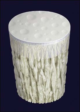
The TRUFIT plug (Smith & Nephew, Andover, Massachusetts, United States) has been designed as a multiphase implant with tailored degradation (Fig. 4D-1). The implant is composed of a polylactic acid (PLA), polylactic glycolide (PLG), and polyglycolic acid (PGA) copolymer, with calcium sulphate, PGA fibers, and surfactant.1,2,3 The bilayer design provides cartilage and bone phases, and initially the cartilage phase is softer and malleable enough to be physically contoured to joint curvature. The plug acts as a porous scaffold that provides structural support while allowing the growth of new healing tissue. The calcium sulphate resorbs in the first several months, and the remaining polymer dissolves over a 12- to 36-month period, allowing for complete filling of the defect by repair tissue.3
Indications/Contraindications
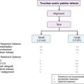
TRUFIT plugs are indicated for the repair of full-thickness articular cartilage or osteochondral lesions.5 The optimal lesion size is less than 2 cm2 to ensure that the plugs are well shouldered by normal surrounding articular cartilage. However, the indication is extended for longitudinal patterns of defects in the articular surface when plugs can be inserted in a line. TRUFIT plugs are not indicated for larger areas where they would be positioned in a circle or group unless a 2 mm or more bone bridge is maintained between plugs.
Surgical Positioning
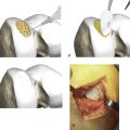
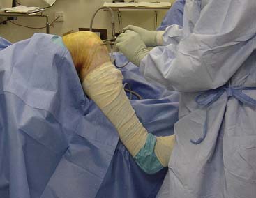
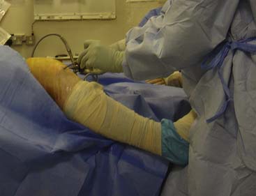
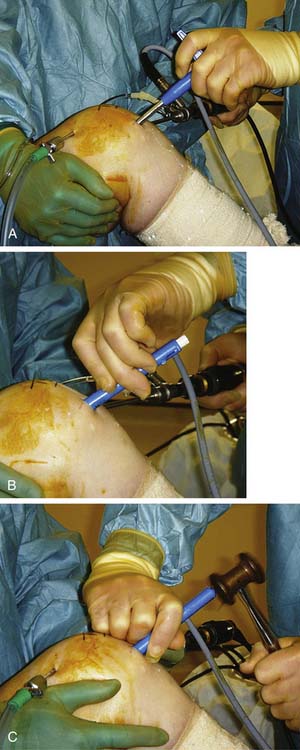
For femoral condyle lesions, the knee is positioned over the edge of the table against the side post and the angle of knee flexion is controlled by pushing the leg against the side of the table (Fig. 4D-2). This makes repositioning of the leg easier than the alternative of positioning the knee at 90 degrees on the table against a foot piece, which holds the knee more rigidly.
For lesions on the trochlea, the leg is positioned nearly straight on the operating table and is supported over a removable sterile bolster (Fig. 4D-3), such as a sandbag or a 3L irrigation fluid bag in a sterile Mayo cover, for example.
Surgical Approach
Regarding the surgical approach, a decision has to be made as to where the lesion is and whether the surgeon is choosing an arthroscopic or a mini-open approach. When considering arthroscopic or a mini-open approach, there are various scenarios that make it more difficult for an arthroscopic technique. It may be quicker to make a small open arthrotomy rather than persevere arthroscopically, and it is certainly easier to visualize the surface to obtain a perpendicular approach.
The central trochlea is also more difficult to approach arthroscopically and again takes a fair amount of levering on the patella. In addition, some knees are simply tight and do not allow easy access. Arthroscopic portals are established to optimize the approach for arthroscopic repair, remembering that the overriding principle is to obtain perpendicular access for the TRUKOR instruments:
Surgical Technique
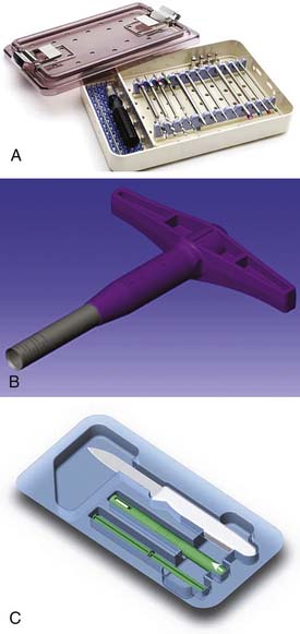
The technique for implanting the TRUFIT plugs is illustrated and detailed in Figures 4D-5 through 4D-14. The instrumentation comes in three parts. The reusable drill bits and sizing instruments are presented in a sterile box (Fig. 4D-4, A). All that is needed beyond these items and the standard arthroscopic instruments is a mallet. The sizers are used to determine the defect size and are matched to the size of the disposable TRUKOR drill sleeve (Fig. 4D-4, B) and TRUFIT CB plug kit (Fig. 4D-4,C).
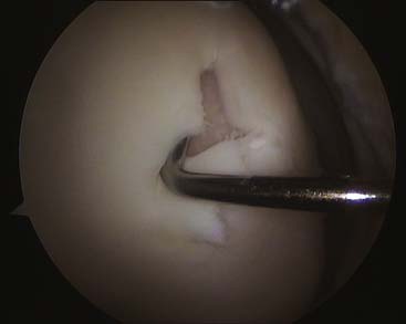
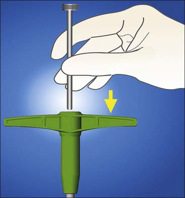
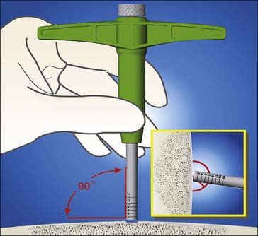
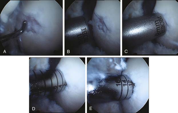
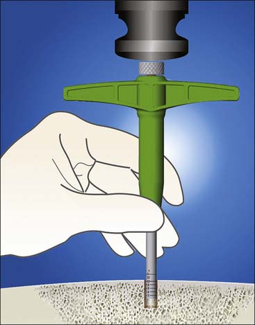
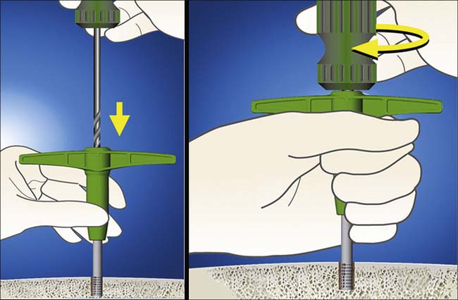
FIGURE 4D-10 The TRUKOR hand drill is inserted and drilled into the bone using firm pressure and twisting.
The main principles of the technique are to do the following:
It is not necessary to fully cover the whole defect, and the area surrounding the plugs can fill in with fibrocartilage.
Specific Steps of the Technique
Step 1
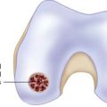
The lesion is probed and sized, taking into account the extent of the unstable cartilage. (Fig. 4D-5)
Step 2
The round-ended obturator is inserted into the chosen TRUKOR drill sleeve to facilitate insertion of the sharp sleeve into the knee (Fig. 4D-6).
Step 3
Once against the defect, the obturator is backed out and the drill sleeve is seated onto the articular surface, taking care to keep it perpendicular. Keeping the obturator in the tube prevents sudden loss of fluid pressure and allows the joint to remain distended (Fig. 4D-7).
Step 4
To check the alignment of the drill sleeve, it must be checked from at least two angles. Figure 4D-8, A, initial view of the cartilage damage. Figure 4D-8, B, mapping defect with a 9-mm sizer. Figure 4D-8, C, checking that the 9-mm sizer covers most of the area. Figure 4D-8, D, the sleeve is gently impacted to the 2-mm line, and this line is then viewed from two or three directions to confirm perpendicular entry. Figure 4D-8, E, the final depth is at 12 mm maximum. (Fig. 4D-8, A-E)
Step 5
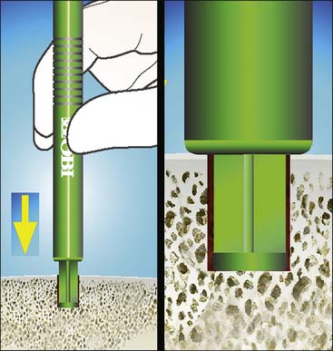
The obturator is then fully removed and the drill sleeve impacted into the bone for 8 to 10 mm, using a mallet. Throughout the impaction, care is taken to ensure the sleeve is maintained perpendicular to the approach (Fig. 4D-9).
Step 6
The TRUKOR hand drill is inserted and drilled into the bone using firm pressure and twisting. A power drill is not usually required, as the drill bit is so sharp (Fig. 4D-10).
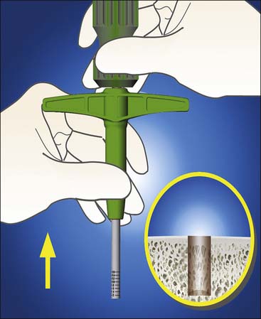
Step 7
Both the drill and the drill sleeve are then removed simultaneously. The drill captures the excised bone to leave a clean defect, and it is not usually necessary to clear the defect of any debris (Fig. 4D-11).
Step 8
The TRUFIT delivery device is opened and the measuring tamp is inserted into the outer sleeve in the direction of the arrow until contact with the preloaded implant is made (Fig. 4D-12).
At this point, the implant should not extend beyond the delivery device.
The measuring tap end is inserted through the skin, into the knee and the defect.
Tip: It is important to ensure that the tamp is fully bottomed out by pushing on the extruded plug. Bear in mind that the outer sleeve needs to be referenced off the intended height of the articular cartilage, not the bottom of the defect; otherwise a false level is achieved.
Step 9
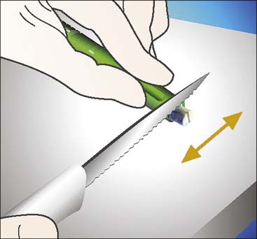
The excess of the protruding plug is then cut, using the sharp, supplied knife. Using the lip of the delivery device as a guide, it is best to use a firm downward motion rather than a sawing action (Fig. 4D-13).
Step 10
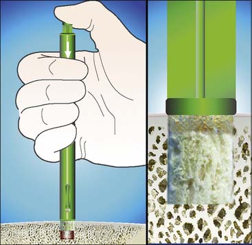
The plug is then delivered into the knee within the delivery device and press-fit into the defect, by pushing on the measuring tamp, either manually or by lightly tapping the plug with a mallet (Fig. 4D-14).
To achieve a flush surface, either the tamp or the metal sizing rod can be used.
Step 11
In Figure 4D-15, A-C, Photographs of the same operation as in Figure 4D-8 show insertion of the plug and final impaction into place using the plastic tamp and the metal sizing rod. Note that the arthroscope is oriented more tangentially along the articular surface than the more usual view of looking down onto it.
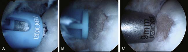
FIGURE 4D-15 A to C Photographs of the same operation as in Figure 4D-8 showing insertion of the plug and final impaction into place using the plastic tamp and the metal sizing rod.
Final positioning is checked by orienting the scope in a different direction to ensure that no edge has lifted up. The knee is cycled and again checked for any impingement from the edge.
Pearls and Pitfalls
Rehabilitation
The overriding principle is that the surface needs to be protected from weight bearing for a short period of time after implantation.
Results
It has been shown that functional scores improved over 12 to 18 months after implantation in a small series of 24 patients.4 Analysis of sequential MRI imaging has shown recovery of the subchondral laminar and gradual remodeling of the bone while the thickness of the articular cartilage is maintained during the differentiation with no or minimal loss of thickness.4
1. Slivka M.A., Leatherbury N.C., Kieswetter K., Niederauer GG. Porous, resorbable, fiber-reinforced scaffolds tailored for articular cartilage repair. Tissue Eng. 2001;7:767-780.
2. Gao C., Gao J., You X., Huo S., Li X., Zhang Y., Zhang W. Fabrication of calcium sulphate/PLLA composite for bone repair. J Biomed Mater Res A. 2005;73A:244-253.
3. Pecora G., De Leonardis D., Ibrahim N., Bovi M., Cornelini R. The use of calcium sulphate in the surgical treatment of a “through and through” periradicular lesion. Int Endod J. 2001;34:189-197.
4. Spalding T. TRUFIT CB plugs for articular cartilage repair in the knee: Early experience and important considerations,” Presentation at the 28th Annual Meeting of the Arthroscopy Association of North America. 2009.