[level-membership-for-orthopaedics-category]
CHAPTER 7 Biomechanics of the Spinal Motion Segment
From a biomechanical standpoint, the spine seems to accomplish three major functions.1 First, the spine provides a structure by which loads can be transmitted through the body. Second, the spine permits motion in multidimensional space. Third, the spine provides a structure to protect the spinal cord. To appreciate the ability of the spine to accomplish these functions, we need to understand the natural movements of the spine and the ability of the spine to withstand forces or loads that are transmitted through the structure.
Physical Characteristics of Spine Structures
Several physiologic curves are also characteristic of the upright spine (Fig. 7–1A). The curves within the cervical and lumbar regions of the spine are referred to as cervical lordosis and lumbar lordosis, whereas the thoracic and sacral curves are referred to as thoracic kyphosis and sacral kyphosis because these curves bow in the opposite direction of the lordotic curves. These curves work collectively to accommodate pelvic orientation under different conditions. When sitting, the pelvis rotates backward and the lumbar curve flattens. When the pelvis is rotated forward, the lumbar curve is accentuated. Collectively, the spinal curves balance each other and form a stable system that maintains the center of gravity in a balanced state.
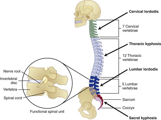
The “building blocks” of the spine are the spinal motion segments (Fig. 7–1B), also known as the functional spinal unit. This unit consists of two vertebrae and the disc in between them. This unit represents the central focus of biomechanical functioning and clinical assessment. This chapter explores the spinal motion segment from a biomechanical perspective with the intent of understanding the significance of features that may influence status.
Support Structures
The spine is constructed of a series of vertebral bones that are stacked on one another to form the spinal column that runs from the pelvis to the head. A vertebral bone, or vertebra, is shown in Figure 7–2. The large round portion of the bone is the vertebral body and represents the major load-bearing structure of the spinal column. The outer portion of this bone is composed of a thin yet very strong layer of cortical bone. Cortical bone, also known as compact bone, forms a protective outer shell, has a high resistance to bending and torsion, and provides strength in situations where bending would be undesirable. The inner portion of the bone consists of a spongy matrix of cancellous bone. This type of bone is less dense and more elastic than cortical bone. Cancellous bone forms the interior scaffolding of the structure and helps the bone to maintain its shape despite compressive forces. This structure is composed of bundles of short and parallel strands of bone fused together.
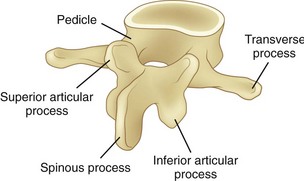
FIGURE 7–2 Lumbar vertebra and its posterior elements.
(Adapted from Marras WS: The Working Back: A Systems View. Hoboken, John Wiley & Sons, 2008.)
Posterior of the vertebral body are bony structures that constitute the posterior elements and form a protective channel or tunnel for the spinal cord (see Fig. 7–1B). The biomechanical role of the posterior elements is to control the position of the vertebral bodies. These elements provide attachment points for muscles to control the position of the vertebra and supply lever arms to provide the system with mechanical advantage. In addition, these structures control motion and provide mechanical “stops” to prevent excessive movement of the vertebral body. A significant portion of the mechanical load is borne by the posterior elements, relieving the disc of excessive loading.
As shown in Figure 7–2, toward the top of the posterior surface of each vertebra are pedicles. The pedicles provide a robust support structure (a type of pillar) to transmit force between the posterior elements and the vertebral body. Projecting out from each pedicle are the lamina structures that come together at the midline of the body and form a neural arch. This arch is a strong structure that provides protection to the spinal cord in the form of a channel (vertebral foramen).
Disc
The disc consists of two distinct portions, each of which is associated with a distinct mechanical function. The outer portion of the disc, called the anulus fibrosus, consists of alternating layers of fibers that are oriented at a 60- to 65-degree angle relative to the vertical. The anulus fibrosus consists of about 10 to 20 concentric, circumferential sheets of collagen called lamellae that are nestled together around the periphery of the disc (Fig. 7–3). The lamellae are stiff and can withstand significant compression loading. Given the collagenous nature of these lamellae, they are pliable and can also permit bending of the spinal column. If the structure were to buckle, however, it would lose its stiffness and would be unable to support compression. The second portion of the disc (nucleus pulposus) is designed to overcome this potential problem.
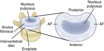
FIGURE 7–3 A, Disc, vertebral endplate, and vertebral body. B, Construction of intervertebral disc.
(Adapted from Marras WS: The Working Back: A Systems View. Hoboken, John Wiley & Sons, 2008; Bogduk N: Clinical Anatomy of the Lumbar Spine and Sacrum, 4th ed. Edinburgh, Churchill Livingstone, 2005.)
Within the anulus fibrosus is a gelatinous core referred to as the nucleus pulposus (see Fig. 7–3). When compressed, this core expands radially and places the anulus fibrosus in tension, providing stiffness. The integrity of the system changes throughout the day. The disc absorbs water while one is recumbent, which makes the system stiffer than when one is upright. Conversely, when one is upright, water is squeezed out of the disc, and the structure becomes more lax.
Spinal Ligaments
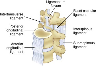
The spinal ligaments are shown in Figure 7–4. The arrangement of these structures provides support for the spine in different dimensions of loading. Because support is offered in the different directions of motion, these structures provide stability when the spinal system is intact.
Coordinate System and Force and Movement Definitions
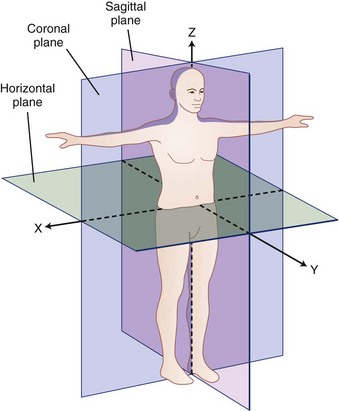
A biomechanical assessment of the spine is concerned with the assessment of movements and forces developing within the spine as it is exposed to activities of daily living and other work or environmental conditions. Movements or motions are compared with the natural limits of movement, and forces imposed on a tissue (also called tissue loading) are compared with the tissue tolerances (magnitude of load at which damage occurs). To describe movement and force transmission through tissue accurately, it is necessary to describe precisely direction of movement and direction and magnitude of the force application on the tissue. Direction is defined relative to a coordinate system or reference frame. The central (global) coordinate system of the body is shown in Figure 7–5. The origin or center of this coordinate system is located at the base of the spine. Figure 7–5 describes the coordinate system (used in this chapter) as a traditional three-dimensional cartesian coordinate system with three mutually perpendicular axes oriented with a vertical Z-axis. Some references have adopted the ISB coordinate convention, where the Y-axis is defined as the vertical axis.
Within the spinal motion segment or functional spinal unit, a local coordinate system can also be defined. The convention that defines this local coordinate system is shown in Figure 7–6. Movement of the spinal motion segments is defined relative to the subjacent vertebrae. Movements of the motion segment can be either translations (indicating straight line movements in any direction) or rotations (indicating movement around a point as when bending).
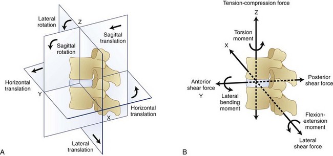
Figure 7–6 indicates that forces and moments (torques) can develop along each dimension of the reference frame. Forces along the Z dimension are either compression or tension depending on whether they compress the spinal motions segment or pull on the tissues. These are typically the forces one is concerned about when lifting an object in the sagittal plane. Two types of shear forces are also of concern when evaluating the biomechanics of the spine. Anteroposterior shear force describes the forward or backward force in the Y-axis that can result from pushing or pulling activities. The lateral shear forces refer to the sideways forces acting along the X-axis and represent the forces that develop in the spinal motion segment when one pushes an object to the side of the body.
Compression of the disc causes pressure within the nucleus pulposus in all directions, and this pressure places the anulus fibrosus under tension. As shown in Figure 7–7, the nucleus pressure can lead to deformation near the center of the endplate with this form of loading.
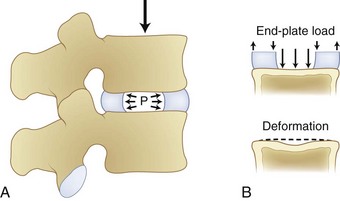
FIGURE 7–7 Compression of disc leading to increased pressure in disc nucleus and deformation of endplate.
(From White AA III, Panjabi MM: Clinical Biomechanics of the Spine, 2nd ed. Philadelphia, JB Lippincott, 1990.)
Figure 7–8 illustrates how shear, torsion, and tension influence the fibers of the anulus. Shear forces tense the fibers in the direction of movement and relax the fibers in the opposite direction. Similarly, torsion or twisting tenses the fibers that are lengthened by the movement and relaxes the remaining fibers. This differential of force among the fibers is believed to result in tissue damage. Finally, lengthening of the spine places the fibers under tension. This action increases the force on all the fibers regardless of their orientation.
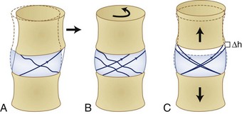
FIGURE 7–8 The effects of shear (A), torsion (B), and tension (C) on the fibers of the anulus fibrosus.
(From Adams MA, Bogduk N, Burton AK, et al: The Biomechanics of Back Pain, 2nd ed. Edinburgh, Churchill Livingstone, 2006.)
Bending moments refer to forces acting around an axis in Figure 7–6. The curved arrows in this figure show the direction in which moments act around a spinal segment. A bending moment can be defined around the X-axis resulting in a movement in the sagittal plane (forward bending moment), or it can be defined around the Y-axis indicating a sideways or lateral bend. In either of these situations, the moment or toque around the central axis defines the loading of the segment. Twisting of the spine can result when forces are applied around the Z-axis of the spine. This situation results in what is typically referred to as torsional moment.
The amount of displacement between the neutral position of the vertebra and the point at which resistance to physiologic motion is experienced is referred to as a neutral zone.2 Neutral zones can be defined for translational and rotational movements. The neutral zone can be described for each of 6 degrees of freedom.
Tissue Load Characteristics
The forces represented in Figure 7–6 define the direction of load application and the magnitude of the force. The nature and temporal characteristics of the loading situation also define the probability that the load application will result in tissue damage. It is believed that tissue damage can result from several different “types” of trauma to the tissue. Each type of trauma is believed to be associated with very different tolerance levels. First, acute trauma is the most familiar type of loading. Acute trauma refers to a single application of force that exceeds the tolerance level of the tissue. This would be the case if a large load were imposed on the spinal motion segment and a rupture of the disc occurred. In this case, the magnitude of the force applied in a particular direction would far exceed the tissue strength of the disc resulting in a rupture.
More recently, a third type of biomechanical trauma (instability) has received much attention in the literature.3–8 Stability is the ability of a system to respond to a perturbation and reestablish a state of equilibrium.2 Instability of the spine refers to the abnormal displacement of spine under physiologic loading. The abnormal displacement can occur in translation or rotation, but most likely would be some combination of these two types of motions. These abnormal motions are often small in magnitude, but the displacement may be enough to stimulate pain in sensitive tissue. Stability is significant because it is often the initiator of tissue damage when the system is out of alignment or when the musculoskeletal system overcompensates for a perturbation.2 When the supporting musculature cannot offer adequate stability to a joint (owing to improper muscle recruitment, fatigue, structure laxity, or weakness), the structure may move abnormally and result in sudden and unexpected force applications on a tissue. This type of trauma is similar to the acute trauma pathway, but is initiated by a miscalculation of the muscle recruitment pattern.
Mechanical Degeneration—Tissues at Risk
Clinicians are beginning to understand that low back disorders can occur before tissue damage. Biochemical studies have shown that these types of tissue insults can result in an upregulation of proinflammatory cytokines. This upregulation may result in tissue inflammation at much lower levels of load than would occur under normal conditions. This inflammation makes nociceptive tissues more sensitive to pain and may initiate back pain.9
When endplate loading exceeds its tolerance limit, microfractures can occur in the structure. Microfracture of the endplate itself usually does not initiate pain because few pain receptors reside within the disc and endplate. Repeated microfracture of this vertebral endplate can lead to the formation of scar tissue and calcification that can interfere with nutrient flow to the disc fibers. Because scar tissue is thicker and denser than endplate tissue, the scar tissue interferes with nutrient delivery to the disc. This reduced nutrient flow can lead to atrophy and weakening of the disc fibers and disc degeneration. Because the disc has relatively few nociceptors except at the outer layers, this degenerative process is usually not noticed by the individual until the disc is weakened to the point where bulging or rupture occurs, and surrounding tissues that are rich in nociceptors are stimulated. Figure 7–9 describes this sequence of events that are believed to lead to disc degeneration.9
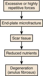
FIGURE 7–9 Sequence of events associated with cumulative or repeated trauma leading to disc degeneration.
The literature also provides some evidence that excessive motion within the spinal segment can lead to degeneration. Excessive motion at a joint is believed to increase the cumulative trauma on the spinal structures and potentially initiate either tissue degeneration or an upregulation of proinflammatory cytokines. This has become apparent in studies that have examined the degeneration of segments adjacent to spinal fusions.10 If two spinal levels are fused, trunk motion usually results in exacerbated movement especially at the facet joints within spinal levels adjacent to the fusion. One study noted hypertrophic degenerative arthritis of the facet joints in motion segments adjacent to a fusion typically following a symptom-free period (8.5 years on average).10 Another study found significant evidence of degeneration at levels adjacent to a fusion with the rate of symptomatic degeneration at the adjacent segment warranting either decompression or arthrodesis to be 16.4% at 5 years after fusion and 36.1% at 10 years after the surgery.11 In addition, more recent studies examining artificial discs have reported facet arthrosis.12 Facet load forces have been shown to depend on artificial disc placement and the subsequent load transferred to the facets.13
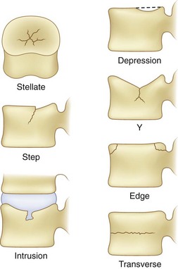
The application of damaging compressive forces on the vertebral body can result in several different types of failures of vertebrae. The failure characteristics have been described in the literature14 and are shown graphically in Figure 7–10. This figure indicates that seven types of failures are typically seen as a result of compression. These consist of stellate fracture, step fracture, intrusion fracture, depression of the endplate, Y-shaped fracture, edge fracture, and transverse fracture. Many of these fractures suggest weakness of the endplate. This weakness is a result of the thinness of the endplate necessary for nutrient transport to the disc. These fractures are believed to result from the nucleus pulposus of the adjacent disc bulging into the vertebra.15
Motion Characteristics (Kinematics) of the Spinal Motion Segments
Spine Kinematics
To appreciate the differences involved in spine impairment, it is important to understand the normal motion or kinematics of the spine. It has been observed that people with low back pain move more slowly.16–18 Motion reduction is assumed to be a result of the “guarding” that occurs in an attempt to minimize the stimulation of pain-producing nociceptors. Abnormal coupling of movement has also been shown to be associated with low back pain.19
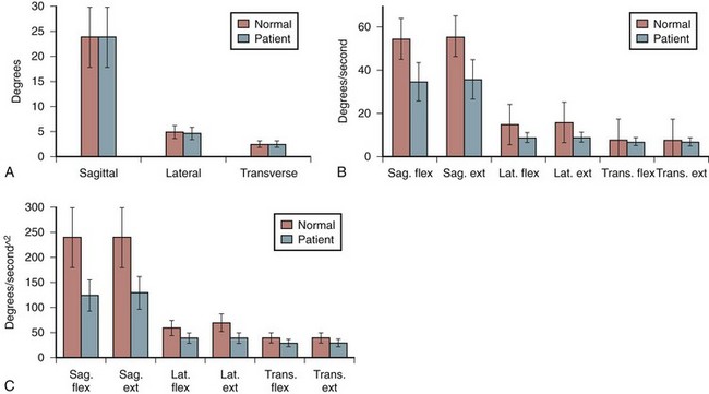
Spine kinematic profiles associated with asymptomatic individuals and people with low back pain have been reported in the literature at least for the lumbar spine. Figure 7–11 summarizes how trunk range of motion, velocity, and acceleration change as a function of low back pain in the sagittal, lateral and transverse planes of the body. There seem to be no differences in range of motion between the low back pain group and the asymptomatic group. Significant differences are apparent, however, when trunk velocity and acceleration are considered. This seems to be the case in all motion planes of the body. More recent studies have shown that kinematic ability can be used to document the extent of a low back disorder.16,17 These differences in velocity and acceleration are believed to be a result of protective “guarding” employed in patients with low back pain through the excessive coactive recruitment of the trunk muscles. This coactivity is believed to slow the motions of the torso.
Segment Kinematics
The typical ranges of motion associated with cervical, thoracic, and lumbar motion segments have been well described in the literature4 and are summarized in Table 7–1. In addition, a graphic estimate of spinal segment range of motion associated with the entire spine is presented in Figure 7–12.2 Table 7–1 shows the vast differences in motion capacity for the various vertebrae as a function of the spine region and the vertebral level. Each region of the spine allows or limits motion in a particular motion direction compared with other regions of the spine. This information shows that in the sagittal plane the most range of motion occurs in the cervical spine followed by the lumbar spine. Lateral directed motions, although much smaller in magnitude than motions in the sagittal plane, occur freely in the cervical spine, with much less movement available in the thoracic and lumbar spine. Finally, very little axial rotation is possible in the lumbar spine, with most motion occurring in the thoracic vertebrae except for C1-C2.
TABLE 7–1 Limits and Representative Values of Ranges of Rotation for Cervical, Thoracic, and Lumbar Spine
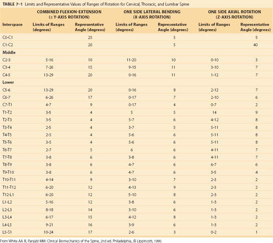
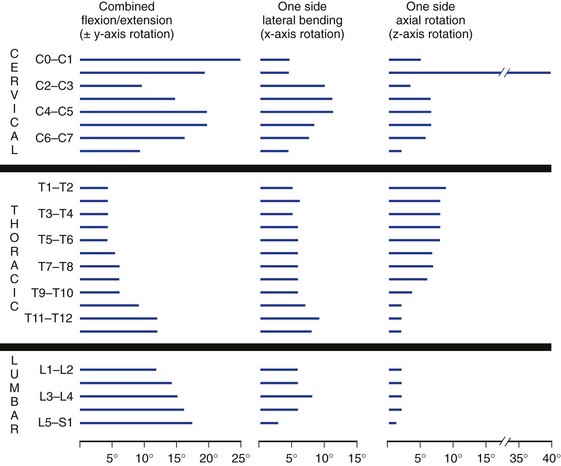
Collectively, the body of work described in Table 7–1 and Figure 7–12 represents the summary of expected movement characteristics derived in vitro. To the extent that in vitro characteristics are indicative of in vivo characteristics, they can provide a baseline for movement expectations for the various vertebrae along the spinal column.
Several studies have also attempted to document the motion of the spinal motion segments in vivo. Figure 7–13 illustrates the estimated normal movement characteristics of the lumbar spine measured in living subjects. This figure indicates significantly different normal movements, particularly in flexion-extension, between in vivo and in vitro observations.20 Figure 7–14 highlights this difference between the in vitro and in vivo observations in the sagittal plane.20 There is a general overestimation of extension movement range in vitro and a general underestimation of flexion range in vitro. In addition, significant differences can be seen between levels between the two states.
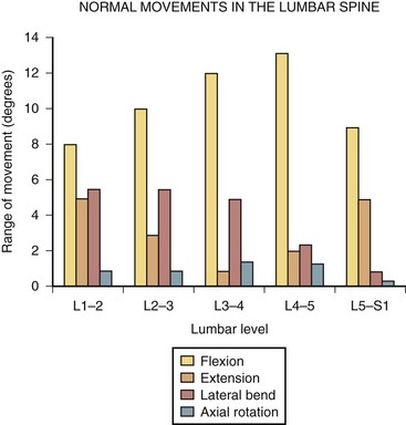
FIGURE 7–13 Ranges of motion in lumbar spine during flexion, extension, lateral bending, and rotation.29,31
(From Adams MA, Bogduk N, Burton AK, et al: The Biomechanics of Back Pain, 2nd ed. Edinburgh, Churchill Livingstone, 2006.)
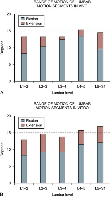
FIGURE 7–14 A and B, Range of flexion and extension motion in lumbar spine measured in vivo (A) and in vitro (B).20,31
(From Adams MA, Bogduk N, Burton AK, et al: The Biomechanics of Back Pain, 2nd ed. Edinburgh, Churchill Livingstone, 2006.)
It is also possible that abnormal movement of the motion segment can indicate disc damage. Studies have also shown that tears in the anulus fibrosus change the movement characteristics of the motion segments. Specifically, tears in the anulus increase the amount of motion in the motion segment when torque is applied to the segment.21
Axis of Rotation
Relative movement of a vertebra can be divided into translational movement (sliding motions) and rotational movement. During physiologic movements, the components of compression force and bending moment acting on the spine vary along with the translational and bending movements. This action results in a varying axis of rotation position. The axis of rotation is defined as a “locus” or path the axis of rotation takes.20
During sagittal and frontal plane motions, the axis of rotation in the cervical spine is believed to be located in the anterior portion of the subjacent vertebra.2 Coupling also occurs with cervical motions, however. In the thoracic spine, loads applied during flexion and extension motions result in an axis of rotation located at the inferior endplate of the lower vertebra. This axis of rotation moves further down the vertebra when posterior shear force occurs during extension motions.2 During flexion and extension motions, the axis of rotation occurs in the superior endplate of the inferior vertebra of the spinal motion segment.
During sagittal plane bending, the axis of rotation varies according to whether forward or backward bending is occurring. Because much of the flexion and extension in the sagittal plane occurs in the lumbar spine, much of the interest in the axis of rotation has also been focused on the lumbar spine. The superior vertebra translates anteriorly and posteriorly relative to the inferior vertebra as the vertebral body rotates around the nucleus. After degeneration of the disc, the axis of rotation can change dramatically22 and result in marked changes in spine loading. Under these degenerative conditions, the axis of rotation has been reported to migrate toward the zygapophyseal joint during extension motions.23 During flexion, the axis of rotation seems to move and is dependent on coupling patterns during the flexion movement.
During lateral motions, the axis of rotation in the lumbar spine lies at the opposite side of the disc from the direction of motion. In other words, when bending to the right, the left side of the disc is where the axis of rotation is located.2
The axis of rotation for axial (torsion) movements has been difficult to locate. This axis of rotation is believed to lie within the posterior anulus fibrosus when exposed to torque.24 Even small axial motion can create compression at one facet surface and tension at the opposite facet surface.5 With disc degeneration, the axis of rotation becomes far less apparent, however, in the lumbar spine.4 Under degenerative conditions, the locus of the axis of rotation has been reported to be significantly spread out over an extended area.25
Motion Coupling
A significant amount of coupling has been observed along the spinal column. Coupling is a function of the geometric characteristics of specific vertebrae, limitations in tissue properties of the disc and ligaments, and spine curvature. Movements are considered coupled when one motion is accompanied by motion in a different plane.2 The motion in the primary or intended plane of movement is referred to as the main motion, and the accompanying motions are referred to as coupled motions.
Coupling is most common in the cervical and lumbar spine, but can also occur in the thoracic spine. Coupling in the cervical and lumbar spine involves axial rotation coupled with lateral bending. Lumbar motion can involve cross-coupling in all three rotation directions. Motions in the lumbar spine are rarely unaccompanied by coupled movements. Coupled motions of the lumbar spine vary as a function of the spine level and a function of spine posture.2
Coupling patterns within the spine differ depending on the region of the spine. The cervical spine exhibits a striking degree of coupling in that lateral bending of the head is accompanied by significant amounts of cervical rotation; this is evident by observing the position of the spinous processes as lateral bending occurs. When lateral bend to the left occurs, the spinous processes point to the right, and when lateral bending to the right occurs, the spinous processes go to the left. It is generally thought that the angle of incline of the facet joints in the sagittal plane increases from the head toward the lower spine.2 Generally, the average ratio of the coupled lateral bending compared with axial rotation is 0.51.26
The coupling of lateral bending and spine rotation can also occur in the thoracic spine. As with the cervical spine, lateral bending is coupled with axial rotation in such a way that the spinous process moves toward the convexity of the lateral curve. The vertebrae in the upper portion of the thoracic spine have motions that are strongly coupled, but not to the same degree as in the cervical spine. In the middle segments of the thoracic spine, the coupling motions are far less apparent. Coupled motions in this portion of the thoracic spine are inconsistent and can result in rotations opposite of those in the upper thoracic spine. Coupling patterns in the lower portion of the thoracic spine are weak. Although the patterns of coupling between axial rotation and lateral bending have been described in the literature, most likely owing to a desire to understand scoliosis, Panjabi and colleagues27 have shown that coupling can occur in all 6 degrees of freedom.
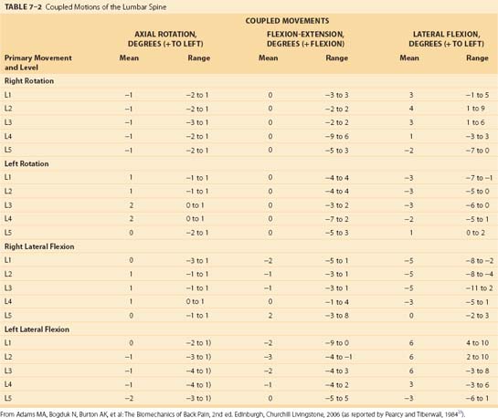
Coupling patterns in the lumbar spine seem to differ from those of the cervical and thoracic spine. The most dominant coupling pattern of the lumbar spine seems to be lateral bending coupled with axial rotation (Table 7–2).28 In this case, the spinous process moves in the same direction as lateral bending. This is exactly opposite the pattern in the cervical and upper thoracic spine. One group of researchers29 reported, however, that coupling at L5-S1 occurs in a fashion similar to that of the lower cervical spine and opposite to that of the rest of the lumbar spine.
In vivo studies of the lumbar spine have shown the importance of muscular involvement in determining coupling patterns of the lumbar spine.29 In vitro studies have reported that lateral bending motion was coupled with flexion motions between L1-L3, whereas in vivo studies reported that lateral motions are coupled with extension movements in these vertebrae. In addition, biomechanical analyses have shown that coupling in the lumbar spine can be influenced by posture of the spine.29,30 One would expect that muscle control can also play an important role in coupling patterns.
Neutral Zone Limits
As discussed earlier, the neutral zone is important for understanding when tissues first experience resistance to movement. Low intersegmental resistance to motion can be an indication of biomechanical problems. The neutral zones for the different planes of motion have been extensively described by Panjabi and colleagues.31–33 Table 7–3 shows estimates for the neutral zones for rotary motions as a function of the plane of motion and the spine level.2 For the most part, the neutral zone is limited in range except for certain vertebrae in certain axes of rotation. From a clinical perspective, one must be sensitive to the fact that normal and abnormal neutral zones can be very different for different vertebrae.
TABLE 7–3 Average Neutral Zone (Degrees of Motion) for Different Spinal Motion Segments in Different Motion Planes
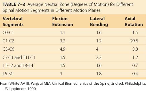
A large neutral zone can be an indication of several biomechanical factors. First, the neutral zone has been observed to increase with age.34 Second, a larger than expected neutral zone can indicate injury to the tissue.35 Third, some clinicians contend that low resistance to movement is an indication of clinical instability.36 There are several reasons to consider carefully the range of movement within the neutral zone.
Load Tolerance of Spinal Motion Segments
Tolerance data limits have been derived primarily from cadaveric tissue. The obvious compromise in this approach is that in vitro tissue when tested does not have the ability to adapt or recover (and potentially increase tolerance) as does a live human. The material properties of cadaveric tissue vary depending on the manner in which the specimen was prepared for testing. At least one study suggests that living tissue failure might occur at magnitudes below those observed in cadaveric specimens.37
Muscle and Tendon Strain
Muscle has the lowest tolerance among the tissues of the spine. The ultimate strength of a muscle has been estimated at 32 MPa.38 Muscle often ruptures before a (healthy) tendon.39 Tendon stress has been estimated to be between 60 MPa and 100 MPa.38,39 There seems to be a safety margin between the muscle failure point and the failure point of the tendon by a factor of about twofold39 to threefold.38
Ligament and Bone Tolerance
A temporal component to ligament recovery has also been reported. One study found that ligaments required extended periods to regain structural integrity. During the recovery period, compensatory muscle activities have been observed.40–47 Recovery time has been observed to be several times the loading duration.
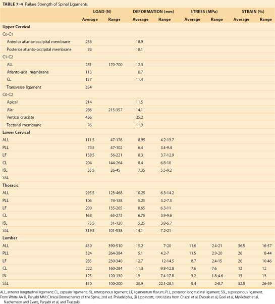
Because the spinal ligaments often are the structure that protects the spinal system, it is important to appreciate the failure limits of the various spinal ligaments; these are shown in Table 7–4. Note that the load tolerance of these ligaments and the deformation characteristics of the ligaments vary markedly according to the region of the spine and the specific ligament involved. Generally, the lower the level of the spinal ligament, the greater is the tolerance of the ligament. There are notable exceptions to this trend, however. Spinal ligaments are viscoelastic and can increase their length under load. They can be responsible for an increase in the neutral zone; excessive movement can also initiate muscle activities intended to regain stability.40,48
Contact Force Tolerance
Contemporary logic suggests that pain secondary to biomechanical loading of the spine may result from direct stimulation to the facet joints, pressure on the anulus, or pressure on the longitudinal ligaments.9 At these sites, inflammatory responses and analgesic responses are thought to be involved in the development of pressure and pain. It is much more difficult to specify load tolerance thresholds for contact pressures because the body’s individual responses to the imposed loads collectively define the pressure imposed on the spinal structure. The tolerance limits for these structures has not been well defined at this time.
Tolerance of Specific Spine Structures
The general structure tolerance, or failure, limits in response to loading of the lumbar spine have been well investigated. Table 7–5 provides a summary of these tolerances reported as a function of the nature of the loading for the spinal motion segment structures and the disc and vertebral body structures.20
TABLE 7–5 Tolerance of Lumbar Motion Segment and Disc Structures as a Function Load and Motion Characteristics
| Failure Site | Average Tolerance | |
|---|---|---|
| Motion Segments | ||
| Compression | Endplate | 5.2 (± 1.8) kN all specimens |
| 6.1 (± 1.8) kN men (20-50 yr old) | ||
| Shear | Neural arch | 2 kN |
| Flexion | Posterior ligaments | 73 (± 18) N-m with compressive load of 0.5-1 kN |
| Extension | Neural arch | 26-45 N-m |
| Torsion | Neural arch | 25-88 N-m |
| Flexion and compression | Disc or vertebra | 5.4 kN |
| Disc plus Vertebral Bodies | ||
| Shear | Anulus | 0.5 kN |
| Flexion | Posterior anulus | 33(± 13 N-m) |
| Torsion | Anulus | 10-31 N-m |
From Adams MA, Bogduk N, Burton AK, et al: The Biomechanics of Back Pain, 2nd ed. Edinburgh, Churchill Livingstone, 2006.
Compression
The compression dimension of spine tolerance has been widely examined. Of all the structures in the spinal motion segment, the endplate is considered to be the “weak point of the system,” or the structure with the lowest tolerance to force. Compression failure limits are a function of age, with older endplates failing at lower levels of force, and gender, with female tolerances lower than male tolerances.49,50 Figure 7–15 shows a summary of the compression strength for much of the spine. The magnitude of force required for endplate tissue failure follows a normal distribution that ranges from 2000 to greater than 14,000 N. When compression forces increase on a spinal motion segment, the first signs of damage usually occur at the endplate or the trabeculae that support the endplate. The endplate must be a thin structure to serve its nutrition transport function. Because it is thin, it is also a very weak structure, however, and subject to early failure when load is applied.
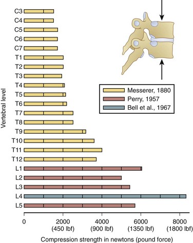
FIGURE 7–15 Estimates of vertebral compression tolerance (strength) under slow load rates for the various vertebrae from C3 to L5.75–77
(From White AA III, Panjabi MM: Clinical Biomechanics of the Spine, 2nd ed. Philadelphia, JB Lippincott, 1990.)
Failure is believed to be initiated by the nucleus pulposus of the adjacent disc. This nucleus causes the endplate to bulge and compromise the vertebral body. The superior endplate is damaged more often than the lower endplate. In some cases, it is possible for a portion of the nucleus pulposus to make its way vertically through a herniation of the endplate into the bone.20 This herniation can calcify and form a Schmorl node. Endplate fractures are difficult to detect via routine radiographs; however, magnetic resonance imaging (MRI) can indicate biologic (modic) changes that are characteristic of vertical displacement of the nucleus pulposus.20
As noted earlier, endplate tolerance seems to be a function of gender and age.49,50 Tolerance estimates based on a review of the literature are shown in Figure 7–16. Although great variability is evident, women generally have lower compression tolerance by an average of almost 2 kN compared with men. In addition, tolerance reduces significantly with age. Age influences endplate tolerance differently between men and women, however. The decrease in tolerance with age is nearly two times greater for men compared with women.49,50 In addition, the strength of the vertebrae is nearly 0.8 kN lower than that of the disc.50 Finally, strength increases as one moves down the lumbar spine by approximately 0.3 kN per lumbar level.51
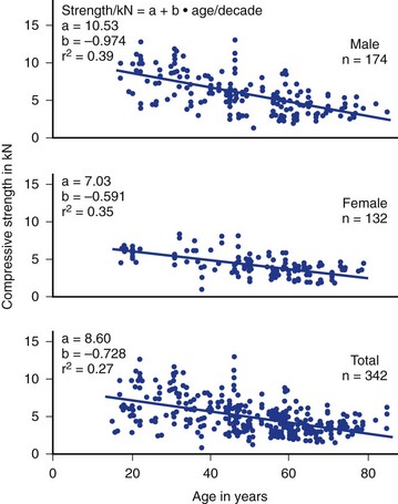
FIGURE 7–16 Strength tolerance to static lumbar compression derived from the literature as a function of age and gender.
(From Jager M, Luttmann A, Laurig W: Lumbar load during one-hand bricklaying. Int J Indust Ergo 8:261-277, 1991.)
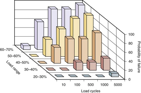
Repetitive loading also seems to influence the tolerance to load of the motion segment. Figure 7–17 shows how the number of load repetitions and the relative magnitude of the load collectively have a dramatic impact on probability of failure of the segment. As can be seen in this figure, when the relative load becomes greater, the chances of failure increase the risk significantly when the number of loading cycles increase.51 Studies have also shown that as the flexion angle increases, the number of cycles required for failure is dramatically reduced.52,53
Shear
The disc fibers and intervertebral ligaments are inadequately oriented to resist shear forces. Shear causes the disc to creep during repetitive loading.54 Under many situations, the neural arch resists shear force, however. The articular process resists on average 2 kN of load before failure; however, this can range from 0.6 to 2.8 kN.55 The specific point of load application can also greatly affect tolerance of the neural arch to shear. Figure 7–18 shows how differing methods of shear force application can result in dramatically different neural arch load tolerances.56,57
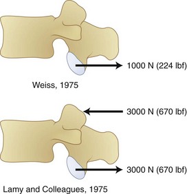
FIGURE 7–18 Force tolerance of neural arch varies greatly as a function of shear force application method.26,57
(From White AA III, Panjabi MM: Clinical Biomechanics of the Spine, 2nd ed. Philadelphia, JB Lippincott, 1990.)
Repetitive shear loading can also reduce the tolerance to 380 N.55 Some authors have concluded that the limit at which shear begins to increase risk is 750 to 1000 N,58–60 although this is also known to vary according to load rate.61,62 In addition, studies have reported failure occurring at the pars under these conditions.
Torsion
The motion segments offer little resistance to small angles of axial rotation. Torsion is first resisted by collagen fibers in the anulus that simply stretch slightly.20,63 With further axial motion, the articular surfaces make contact at one of the zygapophyseal joints, and motion is limited to 1 or 2 degrees.24 This range of motion increases, however, with greater disc degeneration.64–66 Under typical loading conditions (involving torsion and compression), the loads imposed on the spine are shared by several structures. At the limit of the natural range of movement, 30% to 70% of the applied torque is resisted by the zygapophyseal joint as a compressive load, 20% to 50% is resisted by the disc, and less than 15% is resisted by all of the intervertebral ligaments collectively.20,24
The lower limit for initiation of damage owing to torque application seems to begin at about 10 to 30 N-m.24 Many clinicians believe that damage owing to torsional movements occurs at the zygapophyseal joint before damage occurs to the discs.20
Flexion and Extension
Significant repositioning of the spine occurs when flexion and extension of the spine occurs. Different structures are responsible for resisting force, and the tolerance of the spine can change. During extension of the spine, 60% to 70% of the applied load is resisted by the neural arch. Studies have reported damage resulting from 3 to 8 degrees of extension under bending moments of 28 to 45 N-m.67,68 Resistance to extension is offered by the disc and the anterior longitudinal ligament.20 Of particular concern is the risk of the anulus bulging into the vertebral canal and compromising canal space.
Flexion can lead to injury when imposed moments reach 50 to 80 N-m.69–71 Damage occurs when the spinal motion segment reaches 5 to 9 degrees per motion segment in the upper lumbar spine and 10 to 16 degrees per segment in the lower lumbar spine. The first structures to sustain damage are the interspinous and supraspinous ligaments.71 During complex motions involving flexion and lateral bending, the capsular ligaments can also be compromised. The final tissue to fail is the outer posterior anulus fibrosus. In isolation (without the ligaments), the disc can fail when flexed at 18 degrees with an application of 15 to 50 N-m of load.72 As with most structures, load rate also plays a role in tolerance. Resistance to flexion can increase by more than 10% when rapid motions (10 seconds) are compared with slow (1 second) motions.73 Static postures seem to reduce resistance to bending by very large amounts, probably owing to the interrelationship between the ligamentous system and muscular control.42
Lateral Motion
Less has been reported about the tolerance associated with lateral bending moment exposure. Some studies have reported that a lateral bending moment of 10 N-m results in 4 to 6 degrees of lateral bending in the lumbar spine with most of the resistance occurring at the disc.65,74 If the disc experiences degeneration, the range of motion is greatly reduced to 3 to 4 degrees, however, practically eliminating the neutral zone.65
1 Adams MA, Bogduk N, Burton AK, et al. The Biomechanics of Back Pain, 2nd ed. Edinburgh: Churchill Livingstone; 2006.
This book incorporates scientific evidence into a mechanistic review of low back pain pathology.
2 White AA3rd, Panjabi MM. Clinical Biomechanics of the Spine. Philadelphia: Lippincott-Raven; 1990.
3 Marras WS. The Working Back: A Systems View. Hoboken, NJ: John Wiley & Sons; 2008.
4 McGill S. Ultimate Back Fitness and Performance. Waterloo, Canada: Wabuno Publishers; 2004.
This reference shows how biomechanical principles relate to function and rehabilitation of the back.
5 National Research Council (NRC)/Institute of Medicine (IOM). Musculoskeletal Disorders and the Workplace: Low Back and Upper Extremities. Washington, DC: National Academy of Sciences, National Research Council, National Academy Press; 2001.
1 Bernhardt M, White AA3rd, Panjabi MM. Biomechanical considerations of spinal stability. In: Herkowitz HN, Garfin SR, Eismont FJ, et al, editors. Rothman-Simeone The Spine. Philadelphia: WB Saunders, 2006.
2 White AA3rd, Panjabi MM. Clinical Biomechanics of the Spine. Philadelphia: Lippincott-Raven; 1990.
3 Quint U, Wilke HJ, Shirazi-Adl A, et al. Importance of the intersegmental trunk muscles for the stability of the lumbar spine: A biomechanical study in vitro. Spine. 1998;23:1937-1945.
4 Cholewicki J, McGill S. Mechanical stability of the in vivo lumbar spine: Implications of injury and chronic low back pain. Clin Biomech (Bristol, Avon). 1996;11:1-15.
5 Farfan HF, Gracovetsky S. The nature of instability. Spine. 1984;9:714-719.
6 Granata KP, Marras WS. Cost-benefit of muscle cocontraction in protecting against spinal instability. Spine. 2000;25:1398-1404.
7 Panjabi MM. Clinical spinal instability and low back pain. J Electromyogr Kinesiol. 2003;13:371-379.
8 Reeves NP, Narendra KS, Cholewicki J. Spine stability: The six blind men and the elephant. Clin Biomech (Bristol, Avon). 2007;22:266-274.
9 Marras WS. The Working Back: A Systems View. Hoboken, NJ: John Wiley & Sons; 2008.
10 Lee CK. Accelerated degeneration of the segment adjacent to a lumbar fusion. Spine. 1988;13:375-377.
11 Ghiselli G, Wang JC, Bhatia NN, et al. Adjacent segment degeneration in the lumbar spine. J Bone Joint Surg Am. 2004;86:1497-1503.
12 van Ooij A, Oner FC, Verbout AJ. Complications of artificial disc replacement: A report of 27 patients with the SB Charite disc. J Spinal Disord Tech. 2003;16:369-383.
13 Dooris AP, Goel VK, Grosland NM, et al. Load-sharing between anterior and posterior elements in a lumbar motion segment implanted with an artificial disc. Spine. 2001;26:E122-E129.
14 Brinkmann P, Biggermann M, Hilweg D. Prediction of the compressive strength of human lumbar vertebrae. Clin Biomech (Bristol, Avon). 1989;4:S1-S27.
15 Yoganandan N, Larson SJ, Gallagher M, et al. Correlation of microtrauma in the lumbar spine with intraosseous pressures. Spine. 1994;19:435-440.
16 Marras WS, et al. The quantification of low back disorder using motion measures: Methodology and validation. Spine. 1999;24:2091-2100.
17 Marras WS, et al. The classification of anatomic- and symptom-based low back disorders using motion measure models. Spine. 1995;20:2531-2546.
18 Marras WS, Wongsam PE. Flexibility and velocity of the normal and impaired lumbar spine. Arch Phys Med Rehabil. 1986;67:213-217.
19 Stokes IA, Wilder DG, Frymoyer JW, et al. 1980 Volvo award in clinical sciences. Assessment of patients with low-back pain by biplanar radiographic measurement of intervertebral motion. Spine. 1981;6:233-240.
20 Adams MA, Bogduk N, Burton AK, et al. The Biomechanics of Back Pain, 2nd ed. Edinburgh: Churchill Livingstone; 2006.
21 Haughton VM, Schmidt TA, Keele K, et al. Flexibility of lumbar spinal motion segments correlated to type of tears in the annulus fibrosus. J Neurosurg. 2000;92:81-86.
22 Gertzbein SD, et al. Centrode patterns and segmental instability in degenerative disc disease. Spine. 1985;10:257-261.
23 Zhao F, Pollintine P, Hole BD, et al. Discogenic origins of spinal instability. Spine. 2005;30:2621-2630.
24 Adams MA, Hutton WC. The relevance of torsion to the mechanical derangement of the lumbar spine. Spine. 1981;6:241-248.
25 Rolander SD. Motion of the lumbar spine with special reference to the stabilizing effect of posterior fusion: An experimental study on autopsy specimens. Acta Orthop Scand Suppl. 1966;90:1-144.
26 Moroney SP, Schultz AB, Miller JA, et al. Load-displacement properties of lower cervical spine motion segments. J Biomech. 1988;21:769-779.
27 Panjabi MM, Brand RAJr, White AA3rd. Three-dimensional flexibility and stiffness properties of the human thoracic spine. J Biomech. 1976;9:185-192.
28 Bogduk N. Clinical Anatomy of the Lumbar Spine and Sacrum. Edinburgh: Churchill Livingstone; 2005.
29 Pearcy MJ, Tibrewal SB. Axial rotation and lateral bending in the normal lumbar spine measured by three-dimensional radiography. Spine. 1984;9:582-587.
30 Cholewicki J, Crisco JJ3rd, Oxland TR, et al. Effects of posture and structure on three-dimensional coupled rotations in the lumbar spine: A biomechanical analysis. Spine. 1996;21:2421-2428.
31 Pearcy M, Portek I, Shepherd J. Three-dimensional x-ray analysis of normal movement in the lumbar spine. Spine. 1984;9:294-297.
32 Panjabi M, et al. Three-dimensional movements of the upper cervical spine. Spine. 1988;13:726-730.
33 Yamamoto I, Panjabi MM, Crisco T, et al. Three-dimensional movements of the whole lumbar spine and lumbosacral joint. Spine. 1989;14:1256-1260.
34 Mimura M, et al. Disc degeneration affects the multidirectional flexibility of the lumbar spine. Spine. 1994;19:1371-1380.
35 Oxland TR, Panjabi MM. The onset and progression of spinal injury: A demonstration of neutral zone sensitivity. J Biomech. 1992;25:1165-1172.
36 Panjabi MM. The stabilizing system of the spine. Part II: Neutral zone and instability hypothesis. J Spinal Disord. 1992;5:390-396. discussion 397
37 Yoganandan N. Biomechanical identification of injury to an intervertebral joint. Clin Biomech. 1986;1:149.
38 Hoy MG, Zajac FE, Gordon ME. A musculoskeletal model of the human lower extremity: The effect of muscle, tendon, and moment arm on the moment-angle relationship of musculotendon actuators at the hip, knee, and ankle. J Biomech. 1990;23:157-169.
39 Nordin M, Frankel V. Basic Biomechanics of the Musculoskeletal System. Philadelphia: Lea & Febiger; 1989.
40 Solomonow M. Ligaments: A source of work-related musculoskeletal disorders. J Electromyogr Kinesiol. 2004;14:49-60.
41 Solomonow M, Zhou BH, Baratta RV, et al. Biomechanics of increased exposure to lumbar injury caused by cyclic loading. Part 1: Loss of reflexive muscular stabilization. Spine. 1999;24:2426-2434.
42 Solomonow M, Zhou BH, Harris M, et al. The ligamento-muscular stabilizing system of the spine. Spine. 1998;23:2552-2562.
43 Stubbs M, et al. Ligamento-muscular protective reflex in the lumbar spine of the feline. J Electromyogr Kinesiol. 1998;8:197-204.
44 Gedalia U, et al. Biomechanics of increased exposure to lumbar injury caused by cyclic loading. Part 2: Recovery of reflexive muscular stability with rest. Spine. 1999;24:2461-2467.
45 Wang JL, Parnianpour M, Shirazi-Adl A, et al. Viscoelastic finite-element analysis of a lumbar motion segment in combined compression and sagittal flexion: Effect of loading rate. Spine. 2000;25:310-318.
46 Solomonow M, Zhou B, Baratta RV, et al. Neuromuscular disorders associated with static lumbar flexion: A feline model. J Electromyogr Kinesiol. 2002;12:81-90.
47 Solomonow M, et al. Biexponential recovery model of lumbar viscoelastic laxity and reflexive muscular activity after prolonged cyclic loading. Clin Biomech (Bristol, Avon). 2000;15:167-175.
48 Solomonow M, Eversull E, He Zhou B, et al. Neuromuscular neutral zones associated with viscoelastic hysteresis during cyclic lumbar flexion. Spine. 2001;26:E314-E324.
49 Jager M, Luttmann A. Compressive strength of lumbar spine elements related to age, gender, and other influences. J Electromyogr Kinesiol. 1991;1:291-294.
50 Jager M, Luttmann A, Laurig W. Lumbar load during one-hand bricklaying. Int J Indust Ergo. 1991;8:261-277.
51 Brinkmann P, Biggermann M, Hilweg D. Fatigue fracture of human lumbar vertebrae. Clin Biomech (Bristol, Avon). 1988;3:S1-S23.
52 Gallagher S, Marras WS, Litsky AS, et al. Torso flexion loads and the fatigue failure of human lumbosacral motion segments. Spine. 2005;30:2265-2273.
53 Gallagher S, Marras WS, Litsky AS, et al. An exploratory study of loading and morphometric factors associated with specific failure modes in fatigue testing of lumbar motion segments. Clin Biomech (Bristol, Avon). 2006;21:228-234.
54 Cyron BM, Hutton WC. The behaviour of the lumbar intervertebral disc under repetitive forces. Int Orthop. 1981;5:203-207.
55 Cyron BM, Hutton WC, Troup JD. Spondylolytic fractures. J Bone Joint Surg Br. 1976;58:462-466.
56 Lamy C, Bazergui A, Kraus H, et al. The strength of the neural arch and the etiology of spondylolysis. Orthop Clin North Am. 1975;6:215-231.
57 Weiss EB. Stress at the lumbosacral junction. Orthop Clin North Am. 1975;66:83.
58 McGill S. Low Back Disorders: Evidence-Based Prevention and Rehabilitation. Champaign, IL: Human Kinetics; 2002.
59 Marras WS. Occupational low back disorder causation and control. Ergonomics. 2000;43:880-902.
60 NRC/IOM: Musculoskeletal disorders and the workplace: low back and upper extremity. Washington, DC: National Academy of Sciences, National Research Council, National Academy Press. 2001.
61 Yingling VR, McGill SM. Anterior shear of spinal motion segments: Kinematics, kinetics, and resultant injuries observed in a porcine model. Spine. 1999;24:1882-1889.
62 Yingling VR, McGill SM. Mechanical properties and failure mechanics of the spine under posterior shear load: Observations from a porcine model. J Spinal Disord. 1999;12:501-508.
63 Adams MA, Dolan P. Spine biomechanics. J Biomech. 2005;38:1972-1983.
64 Oxland TR, Crisco JJ3rd, Panjabi MM, et al. The effect of injury on rotational coupling at the lumbosacral joint: A biomechanical investigation. Spine. 1992;17:74-80.
65 Oxland TR, et al. The relative importance of vertebral bone density and disc degeneration in spinal flexibility and interbody implant performance: An in vitro study. Spine. 1996;21:2558-2569.
66 Oxland TR, Grant JP, Dvorak MF, et al. Effects of endplate removal on the structural properties of the lower lumbar vertebral bodies. Spine. 2003;28:771-777.
67 Adams MA, Dolan P, Hutton WC. The lumbar spine in backward bending. Spine. 1988;13:1019-1026.
68 Green TP, Allvey JC, Adams MA. Spondylolysis: Bending of the inferior articular processes of lumbar vertebrae during simulated spinal movements. Spine. 1994;19:2683-2691.
69 Adams MA, Dolan P. A technique for quantifying the bending moment acting on the lumbar spine in vivo. J Biomech. 1991;24:117-126.
70 Adams MA, Hutton WC. The effect of posture on diffusion into lumbar intervertebral discs. J Anat. 1986;147:121-134.
71 Adams MA, Hutton WC, Stott JR. The resistance to flexion of the lumbar intervertebral joint. Spine. 1980;5:245-253.
72 Adams MA, Green TP, Dolan P. The strength in anterior bending of lumbar intervertebral discs. Spine. 1994;19:2197-2203.
73 Adams MA, Dolan P. Time-dependent changes in the lumbar spine’s resistance to bending. Clin Biomech (Bristol, Avon). 1996;11:194-200.
74 Peng B, et al. Possible pathogenesis of painful intervertebral disc degeneration. Spine. 2006;31:560-566.
75 Bell GH, Dunbar O, Beck JS, et al. Variations in strength of vertebrae with age and their relation to osteoporosis. Calcif Tissue Res. 1967;1:75-86.
76 Messerer O. Gottaschen Buchhandling. JG Stutgart, 1880.
77 Perry O. Encyclopedia of Medical Radiology. New York: Springer-Verlag, 1974.
[/level-membership-for-orthopaedics-category][not-level-membership-for-orthopaedics-category]
CHAPTER 7 Biomechanics of the Spinal Motion Segment
From a biomechanical standpoint, the spine seems to accomplish three major functions.1 First, the spine provides a structure by which loads can be transmitted through the body. Second, the spine permits motion in multidimensional space. Third, the spine provides a structure to protect the spinal cord. To appreciate the ability of the spine to accomplish these functions, we need to understand the natural movements of the spine and the ability of the spine to withstand forces or loads that are transmitted through the structure.
Physical Characteristics of Spine Structures
Several physiologic curves are also characteristic of the upright spine (Fig. 7–1A). The curves within the cervical and lumbar regions of the spine are referred to as cervical lordosis and lumbar lordosis, whereas the thoracic and sacral curves are referred to as thoracic kyphosis and sacral kyphosis because these curves bow in the opposite direction of the lordotic curves. These curves work collectively to accommodate pelvic orientation under different conditions. When sitting, the pelvis rotates backward and the lumbar curve flattens. When the pelvis is rotated forward, the lumbar curve is accentuated. Collectively, the spinal curves balance each other and form a stable system that maintains the center of gravity in a balanced state.
The “building blocks” of the spine are the spinal motion segments (Fig. 7–1B), also known as the functional spinal unit. This unit consists of two vertebrae and the disc in between them. This unit represents the central focus of biomechanical functioning and clinical assessment. This chapter explores the spinal motion segment from a biomechanical perspective with the intent of understanding the significance of features that may influence status.
Support Structures
The spine is constructed of a series of vertebral bones that are stacked on one another to form the spinal column that runs from the pelvis to the head. A vertebral bone, or vertebra, is shown in Figure 7–2. The large round portion of the bone is the vertebral body and represents the major load-bearing structure of the spinal column. The outer portion of this bone is composed of a thin yet very strong layer of cortical bone. Cortical bone, also known as compact bone, forms a protective outer shell, has a high resistance to bending and torsion, and provides strength in situations where bending would be undesirable. The inner portion of the bone consists of a spongy matrix of cancellous bone. This type of bone is less dense and more elastic than cortical bone. Cancellous bone forms the interior scaffolding of the structure and helps the bone to maintain its shape despite compressive forces. This structure is composed of bundles of short and parallel strands of bone fused together.
FIGURE 7–2 Lumbar vertebra and its posterior elements.
(Adapted from Marras WS: The Working Back: A Systems View. Hoboken, John Wiley & Sons, 2008.)
Posterior of the vertebral body are bony structures that constitute the posterior elements and form a protective channel or tunnel for the spinal cord (see Fig. 7–1B). The biomechanical role of the posterior elements is to control the position of the vertebral bodies. These elements provide attachment points for muscles to control the position of the vertebra and supply lever arms to provide the system with mechanical advantage. In addition, these structures control motion and provide mechanical “stops” to prevent excessive movement of the vertebral body. A significant portion of the mechanical load is borne by the posterior elements, relieving the disc of excessive loading.
As shown in Figure 7–2, toward the top of the posterior surface of each vertebra are pedicles. The pedicles provide a robust support structure (a type of pillar) to transmit force between the posterior elements and the vertebral body. Projecting out from each pedicle are the lamina structures that come together at the midline of the body and form a neural arch. This arch is a strong structure that provides protection to the spinal cord in the form of a channel (vertebral foramen).
Disc
The disc consists of two distinct portions, each of which is associated with a distinct mechanical function. The outer portion of the disc, called the anulus fibrosus, consists of alternating layers of fibers that are oriented at a 60- to 65-degree angle relative to the vertical. The anulus fibrosus consists of about 10 to 20 concentric, circumferential sheets of collagen called lamellae that are nestled together around the periphery of the disc (Fig. 7–3). The lamellae are stiff and can withstand significant compression loading. Given the collagenous nature of these lamellae, they are pliable and can also permit bending of the spinal column. If the structure were to buckle, however, it would lose its stiffness and would be unable to support compression. The second portion of the disc (nucleus pulposus) is designed to overcome this potential problem.
FIGURE 7–3 A, Disc, vertebral endplate, and vertebral body. B, Construction of intervertebral disc.
(Adapted from Marras WS: The Working Back: A Systems View. Hoboken, John Wiley & Sons, 2008; Bogduk N: Clinical Anatomy of the Lumbar Spine and Sacrum, 4th ed. Edinburgh, Churchill Livingstone, 2005.)
Within the anulus fibrosus is a gelatinous core referred to as the nucleus pulposus (see Fig. 7–3). When compressed, this core expands radially and places the anulus fibrosus in tension, providing stiffness. The integrity of the system changes throughout the day. The disc absorbs water while one is recumbent, which makes the system stiffer than when one is upright. Conversely, when one is upright, water is squeezed out of the disc, and the structure becomes more lax.
Spinal Ligaments
The spinal ligaments are shown in Figure 7–4. The arrangement of these structures provides support for the spine in different dimensions of loading. Because support is offered in the different directions of motion, these structures provide stability when the spinal system is intact.
Coordinate System and Force and Movement Definitions
A biomechanical assessment of the spine is concerned with the assessment of movements and forces developing within the spine as it is exposed to activities of daily living and other work or environmental conditions. Movements or motions are compared with the natural limits of movement, and forces imposed on a tissue (also called tissue loading) are compared with the tissue tolerances (magnitude of load at which damage occurs). To describe movement and force transmission through tissue accurately, it is necessary to describe precisely direction of movement and direction and magnitude of the force application on the tissue. Direction is defined relative to a coordinate system or reference frame. The central (global) coordinate system of the body is shown in Figure 7–5. The origin or center of this coordinate system is located at the base of the spine. Figure 7–5 describes the coordinate system (used in this chapter) as a traditional three-dimensional cartesian coordinate system with three mutually perpendicular axes oriented with a vertical Z-axis. Some references have adopted the ISB coordinate convention, where the Y-axis is defined as the vertical axis.
Within the spinal motion segment or functional spinal unit, a local coordinate system can also be defined. The convention that defines this local coordinate system is shown in Figure 7–6. Movement of the spinal motion segments is defined relative to the subjacent vertebrae. Movements of the motion segment can be either translations (indicating straight line movements in any direction) or rotations (indicating movement around a point as when bending).
Figure 7–6 indicates that forces and moments (torques) can develop along each dimension of the reference frame. Forces along the Z dimension are either compression or tension depending on whether they compress the spinal motions segment or pull on the tissues. These are typically the forces one is concerned about when lifting an object in the sagittal plane. Two types of shear forces are also of concern when evaluating the biomechanics of the spine. Anteroposterior shear force describes the forward or backward force in the Y-axis that can result from pushing or pulling activities. The lateral shear forces refer to the sideways forces acting along the X-axis and represent the forces that develop in the spinal motion segment when one pushes an object to the side of the body.
Compression of the disc causes pressure within the nucleus pulposus in all directions, and this pressure places the anulus fibrosus under tension. As shown in Figure 7–7, the nucleus pressure can lead to deformation near the center of the endplate with this form of loading.
FIGURE 7–7 Compression of disc leading to increased pressure in disc nucleus and deformation of endplate.
(From White AA III, Panjabi MM: Clinical Biomechanics of the Spine, 2nd ed. Philadelphia, JB Lippincott, 1990.)
Figure 7–8 illustrates how shear, torsion, and tension influence the fibers of the anulus. Shear forces tense the fibers in the direction of movement and relax the fibers in the opposite direction. Similarly, torsion or twisting tenses the fibers that are lengthened by the movement and relaxes the remaining fibers. This differential of force among the fibers is believed to result in tissue damage. Finally, lengthening of the spine places the fibers under tension. This action increases the force on all the fibers regardless of their orientation.
FIGURE 7–8 The effects of shear (A), torsion (B), and tension (C) on the fibers of the anulus fibrosus.
(From Adams MA, Bogduk N, Burton AK, et al: The Biomechanics of Back Pain, 2nd ed. Edinburgh, Churchill Livingstone, 2006.)
Bending moments refer to forces acting around an axis in Figure 7–6. The curved arrows in this figure show the direction in which moments act around a spinal segment. A bending moment can be defined around the X-axis resulting in a movement in the sagittal plane (forward bending moment), or it can be defined around the Y-axis indicating a sideways or lateral bend. In either of these situations, the moment or toque around the central axis defines the loading of the segment. Twisting of the spine can result when forces are applied around the Z-axis of the spine. This situation results in what is typically referred to as torsional moment.
The amount of displacement between the neutral position of the vertebra and the point at which resistance to physiologic motion is experienced is referred to as a neutral zone.2 Neutral zones can be defined for translational and rotational movements. The neutral zone can be described for each of 6 degrees of freedom.
Tissue Load Characteristics
The forces represented in Figure 7–6 define the direction of load application and the magnitude of the force. The nature and temporal characteristics of the loading situation also define the probability that the load application will result in tissue damage. It is believed that tissue damage can result from several different “types” of trauma to the tissue. Each type of trauma is believed to be associated with very different tolerance levels. First, acute trauma is the most familiar type of loading. Acute trauma refers to a single application of force that exceeds the tolerance level of the tissue. This would be the case if a large load were imposed on the spinal motion segment and a rupture of the disc occurred. In this case, the magnitude of the force applied in a particular direction would far exceed the tissue strength of the disc resulting in a rupture.
More recently, a third type of biomechanical trauma (instability) has received much attention in the literature.3–8 Stability is the ability of a system to respond to a perturbation and reestablish a state of equilibrium.2 Instability of the spine refers to the abnormal displacement of spine under physiologic loading. The abnormal displacement can occur in translation or rotation, but most likely would be some combination of these two types of motions. These abnormal motions are often small in magnitude, but the displacement may be enough to stimulate pain in sensitive tissue. Stability is significant because it is often the initiator of tissue damage when the system is out of alignment or when the musculoskeletal system overcompensates for a perturbation.2 When the supporting musculature cannot offer adequate stability to a joint (owing to improper muscle recruitment, fatigue, structure laxity, or weakness), the structure may move abnormally and result in sudden and unexpected force applications on a tissue. This type of trauma is similar to the acute trauma pathway, but is initiated by a miscalculation of the muscle recruitment pattern.
Mechanical Degeneration—Tissues at Risk
Clinicians are beginning to understand that low back disorders can occur before tissue damage. Biochemical studies have shown that these types of tissue insults can result in an upregulation of proinflammatory cytokines. This upregulation may result in tissue inflammation at much lower levels of load than would occur under normal conditions. This inflammation makes nociceptive tissues more sensitive to pain and may initiate back pain.9
When endplate loading exceeds its tolerance limit, microfractures can occur in the structure. Microfracture of the endplate itself usually does not initiate pain because few pain receptors reside within the disc and endplate. Repeated microfracture of this vertebral endplate can lead to the formation of scar tissue and calcification that can interfere with nutrient flow to the disc fibers. Because scar tissue is thicker and denser than endplate tissue, the scar tissue interferes with nutrient delivery to the disc. This reduced nutrient flow can lead to atrophy and weakening of the disc fibers and disc degeneration. Because the disc has relatively few nociceptors except at the outer layers, this degenerative process is usually not noticed by the individual until the disc is weakened to the point where bulging or rupture occurs, and surrounding tissues that are rich in nociceptors are stimulated. Figure 7–9 describes this sequence of events that are believed to lead to disc degeneration.9
[/not-level-membership-for-orthopaedics-category]
