CHAPTER 78 Biomechanics of the Intervertebral Disc
INTRODUCTION: STRUCTURE AND FUNCTION OF DISC
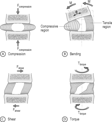
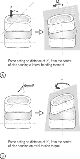
The intervertebral disc separates the rigid vertebral bodies and allows for large, complex, three-dimensional motion of the spine. The disc, therefore, must be soft enough to permit spinal motions of axial compression, flexion–extension, lateral bending, and axial rotation, all of which subject the disc to compressive, bending, shear, and torsional forces, respectively (Fig. 78.1). At the same time, the disc must be stiff enough to maintain stability and withstand the large loads encountered as the lumbar spine progresses through the physiologic motions required by daily living. This is accomplished in part by the disc’s unique ability to absorb and dissipate energy that is generated during these activities. Clearly, the primary function of the disc is mechanical. Therefore, an appreciation of normal and degenerative disc biomechanics is critical to understanding the etiology and sequelae of disc disease, as well as the consequences of intervention.
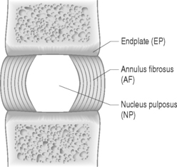
The disc is composed of substructures which are themselves distinct tissues: the nucleus pulposus, anulus fibrosus, and cartilaginous endplates (Fig. 78.2).1 The composition and structure of these disc components are summarized briefly below.
When the disc degenerates, its biochemical, cellular, structural, and mechanical functions are compromised. Some of these changes include anulus fibrosus fissures and tears, nucleus pulposus loss of proteoglycan and depressurization, endplate calcification and failure, and cell senescence and death.2 Despite the widely accepted notion that disc degeneration is an important potential source of back pain, a clear link between disc pathology and back pain has not yet been established. Further, a clear distinction between physiologic aging of the disc and disc degeneration has not been delineated. Nevertheless, while the precise mechanisms by which the disc may produce back pain have yet to be identified, disc degeneration is considered an important potential source of pain and the subject of continued intense investigation.3,4
BASIC BIOMECHANICS
Basic biomechanics terminology
Biomechanics deals with the study of forces and displacements acting on biological materials and their resulting effects. In this section, basic biomechanical terminology and principles are defined and applied to the disc. A more detailed explanation of these biomechanical concepts can be found in two excellent texts written for nonengineers by Low and Read5 and Panjabi and White.6
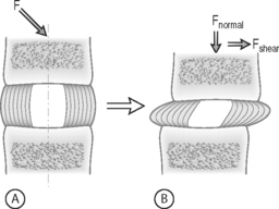
FORCE: Force is an action that moves or deforms a body – a push or a pull. It is a vector quantity often depicted using an arrow which indicates a magnitude, direction, and a point of application. Figure 78.3 demonstrates these actions applied to a spinal motion segment. The unit of force is a Newton. Complex forces are usually broken down into their ‘components.’ For example, the generic applied force in Figure 78.3A is broken down into its components of normal force and shear force as shown in Figure 78.3B.
BENDING MOMENT OR TORQUE: When a force is applied at some distance from the center of an object it may cause a bending or turning effect, which is known as a moment or a torque (Fig. 78.4). Moment and torque are both defined as the magnitude of the force times the lever arm (the perpendicular distance between the force and the chosen center of rotation). The units for bending and torque are N-mm or N-m, depending on the scale of the objects considered. Bending moment and torque are the same except that generally in bending the force and lever arm are in the plane parallel to the axis of the structure (Fig. 78.4A), while for a torque they are perpendicular to the axis of the structure (Fig. 78.4B). An example of a bending moment is forward flexion, where the weight of the upper body times its distance from the spine is the applied bending moment. An example of torque is the torso twisting along the long axis of the body. Another example is when a screwdriver is turned; in this case, the force applied to the handle times the diameter of the handle is the torque. The clinical application of moments and torques in the spine explains how seemingly small forces may generate significant moments as a result of large lever arms.
STRESS: Force is generally not applied at a single point, but is distributed over a contact area. This distribution of force, or load intensity, is defined as stress. Stress is the ratio of force divided by the area of application and usually has the units of N/mm2 (MPa or Megapascals) or N/m2 (Pascals), depending on the size scale. Stress is sometimes defined in Imperial units as pounds per square inch (psi). Stress can be broken down into its components, as is done for force. The force components shown in Figure 78.3B, when divided by the disc surface area, can be used to calculate the applied compressive and shear stress. Externally applied stresses on an object give rise to internal stresses.
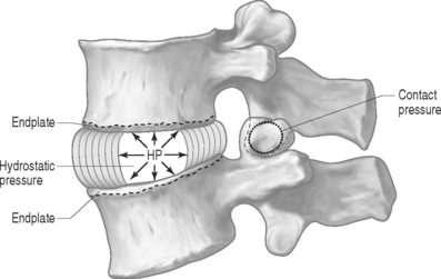
PRESSURE: There are two types of pressures: contact pressure and fluid pressure (Fig. 78.5). Contact pressure occurs in solids and is an applied compressive stress. For example, the contact of the two facet joint surfaces imposes a compressive stress that is sometimes called a contact pressure. Importantly, fluid pressure, also known as hydrostatic pressure, occurs in contained fluids and should not be confused with solid stress or contact stress, even though it has the same units. Fluid pressure is the intensity of loading within a contained fluid. The fluid pressure is generated by the interactions of the fluid molecules with the surface of its container. Hydrostatic pressure is isotropic, which means that it is the same in all directions. The nucleus pulposus of the disc is considered to be a fluid (or fluid-like) substance and therefore generates a hydrostatic pressure when the disc is loaded. This pressure is the same in all directions: vertically against the endplates and radially against the containing walls of the anulus fibrosus, as shown in Figure 78.5.
Soft tissue mechanical behaviors
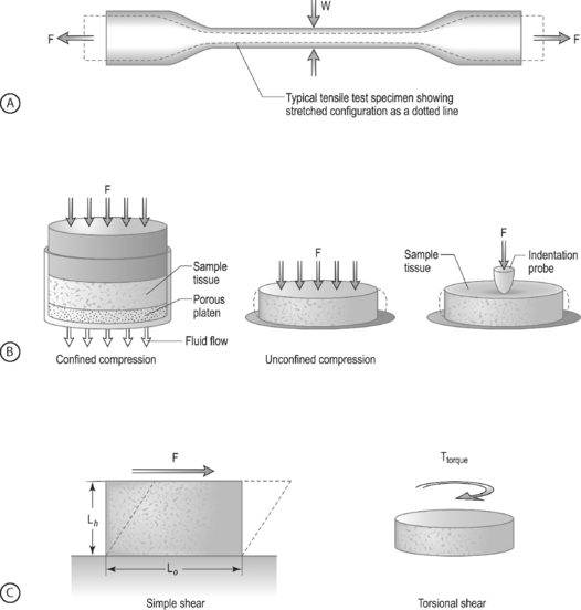
LOADING CONFIGURATIONS: There are three standard mechanical testing configurations for soft tissues: tension, compression, and shear. For tension and compression experiments the specimen ends are pulled away from each other (tension) or pushed towards each other (compression). In a tension test, the specimen is generally long and thin (Fig. 78.6A) and is held in the testing machine at both ends. The specimen ends are pulled apart leading to an increase in the length and decrease in width. In a compression test, the sample is generally a short cylinder, and the two ends of the specimen are pushed towards each other resulting in a decrease in the height of the specimen (Fig. 78.6B). For shear loading tests, a sample may be either rectangular or cylindrical and the load is applied parallel to the surface (Fig. 78.6C). The sample then changes its shape without undergoing either compression or tension.
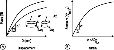
STRUCTURAL AND MATERIAL PROPERTIES: A biomechanical study typically involves experimentation and curve-fitting to a mathematical equation to determine the relationship between the force and displacement. However, for specimens of the same material with different dimensions, the force–displacement curves will be different, as shown in Figure 78.7A. This is because both force and displacement are ‘as measured’ quantities and not normalized with respect to the specimen geometry (e.g. cross-sectional area and height). Thus, it is important that the data for force and displacement be normalized to enable comparisons among different-sized samples. These principles have led to the development of normalized quantities such as stress and strain. The stress–strain response of the same material prepared into samples of different sizes is the same (Fig. 78.7B). The slope of this curve is defined as the modulus of the material and has the units of MPa or N/mm2. Similarly, the slope of the force versus displacement curve is defined as the stiffness and has the units of N/mm. For tension and compression testing, Poisson’s ratio is defined as the negative of the lateral contraction strain divided by the applied longitudinal strain. In shear testing, the shear modulus is calculated as the slope of the shear stress (applied parallel to the sample surface) versus the angle of displacement.
NONLINEARITY: A material is nonlinear if the force–displacement or stress–strain response does not have constant slope. While many materials are linear, most biological materials are nonlinear. Consequently, a single stiffness or modulus cannot describe the tissue’s behavior over all loading levels. In motion segment mechanics, this nonlinearity is exemplified by the dramatically different behavior in the low-stiffness neutral zone compared to the high-stiffness loading zones (Fig.78.8A). In soft tissue mechanics, nonlinearity is observed by the low ‘toe region’ modulus and the larger ‘linear region’ modulus (Fig. 78.8B). The large differences in compressive and tensile properties are another form of material nonlinearity.
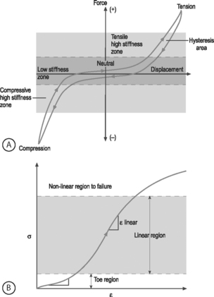
Nonlinearity in a spine motion segment is observed as the very large changes in stiffness as the motion segment is moved through the range of motion in any single loading direction. This is an important mechanical behavior because it contributes to the overall range of motion and because an increase in the neutral zone length is consistently observed in degenerated discs.7 A typical cyclic load response of an intervertebral disc is shown in Figure 78.8A. The curve is characterized by high stiffness regions at the extreme ends of loading and by a low stiffness region at low loads. The region of the response in the low load (or moment) and low deformation (or rotation) region is called the ‘neutral zone.’ The neutral zone is defined as the region on either side of the neutral position where there is little or no resistance to motion.7,8 The neutral zone mechanical properties are used to understand the stability of the disc motion segment. Although early studies reported the neutral zone as simply the displacement (rotation) over which loads (moments) are negligible, recent studies have focused on quantifying this important region of disc mechanical function.9,10
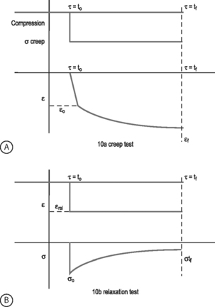
VISCOELASTICITY: All biological tissues, including disc, bone, cartilage, muscle, tendon, and ligaments, exhibit viscoelastic behaviors. A material is viscoelastic if it has time-dependent mechanical behaviors. For example, if a constant compression load (load-control) is applied to a spine segment it will immediately deform (the elastic response) and it will slowly continue to deform over the next several minutes and hours (the viscous response). The most commonly used test to evaluate tissue viscoelasticity in the spine is called a creep test (Fig. 78.9A). The analogous test applied under a constant displacement (displacement-control) is called a stress-relaxation test (Fig. 78.9B). In this case, a constant displacement is applied to the spine segment which immediately experiences a stress (the elastic response). Over the next few minutes or hours, the segment relaxes to a lower stress value (the viscous response). In a viscoelastic experiment, the stress (relaxation) or strain (creep) data are applied to a best-fit curve, the constants from which permit comparisons among different specimens. Another viscoelastic response is hysteresis, which describes a difference of cyclic loading in the load-displacement curve in the loading and unloading phases. The intervening area in this curve is described as the hysteresis area, and represents energy lost as heat due to viscous effects (see Fig. 78.8A).
TISSUE MECHANICS OF DISC SUBSTRUCTURES
Nucleus pulposus mechanics
The nucleus pulposus is a highly hydrated gel with important material properties that include swelling pressure, compression modulus, permeability, and shear modulus. The nucleus has a large water and proteoglycan content. Proteoglycans have negatively charged glycosaminoglycans attached, which attract positive ions and generate high osmotic pressures. If the nucleus pulposus is removed and placed in a hydrating solution it swells to at least two times its volume. The nucleus swelling pressure has been measured using a pressure transducer in vivo and in excised cadaveric spines under mechanical loading. The swelling pressure of a healthy nucleus is 0.1–0.2 MPa in a recumbent position and may reach as high as 1–3 MPa when standing or lifting.11,12 Similarly high pressures have been measured in cadaveric motion segments under externally applied loads.13,14 The swelling pressure has also been measured using osmometry methods15 and in confined compression,16 producing values consistent with in vivo measurements. The nucleus pulposus swelling pressure has been shown to be correlated with the glycosaminoglycans content.15,16
The large propensity of the nucleus pulposus to swell makes it difficult to prepare test samples and to measure its mechanical properties. As a result, there is a paucity of studies in the literature which have examined these properties. This dearth of mechanical data has made it difficult to properly model the nucleus pulposus in finite element studies of the spine. Lack of mechanical data has also hampered the development of tissue-engineered and artificial disc replacements because clear targets for mechanical function are needed. Fortunately, recent studies have provided measures of the tissue properties and their changes with degeneration. The equilibrium shear modulus of nondegenerate human nucleus pulposus is 0.2 kPa and increases to 0.6–0.8 kPa with degeneration.17 The high water content of the nucleus pulposus contributes to the large viscoelastic effects observed. Further, the dynamic shear modulus is almost two orders of magnitude larger than the equilibrium modulus, ranging 5–60 kPa17 and increases with degeneration. When dynamic loading is applied in shear, the nucleus behaves like a viscoelastic solid, suggesting that finite element models that describe the nucleus as a fluid may miss important behaviors.18 The compression modulus measured at equilibrium in a confined compression test is three orders of magnitude higher than the shear modulus at 0.5 MPa for nondegenerate human tissue.16 The viscoelastic behavior, as measured by the hydraulic permeability, was calculated to be 3 × 10⁻¹⁶ m4/Ns.16
The nucleus pulposus is the first disc substructure to exhibit degenerative changes: the shear stiffness increases,18 the pressure decreases,15 the compression stiffness increases,16 the permeability decreases,16 and its compositional changes lead to a shift from a fluid-like behavior to a solid-like behavior.17 When the nucleus is degenerated, the swelling pressure decreases dramatically to 0.03 MPa or less.11,12,16,19 While stiffness increases with degeneration and the behaviors become more solid-like, osmometry and mechanical compression tests show that even with degeneration the overall behavior of the nucleus pulposus is still dominated by the swelling component.16,20 These biochemical changes observed in the degenerating nucleus pulposus and their biomechanical consequences may be key factors in further progression of degeneration.
Anulus fibrosus mechanics
COMPRESSION: The anulus fibrosus undergoes large compression loads during the activities of daily living due to both axial loading and as a result of bending and torsional loading. The primary directions for compression loading in the anulus are in the axial direction, due to body weight, and in the radial direction, due to nucleus pulposus swelling. The swelling pressure represents the pressure generated when the anulus is held at the in situ displacement. Swelling pressure correlates with the biochemical content of glycosaminoglycan due to the osmotic pressures generated by balancing their negative charges. Since the glycosaminoglycan content is high in the anulus fibrosus (and nucleus pulposus), the swelling pressure is an important material parameter. Confined compression experiments and biphasic analyses have revealed the material properties of solid matrix modulus and permeability. The anulus compressive modulus is 0.6 MPa and the permeability is 2 × 10⁻¹⁶ m4/Ns.21,22
The anulus behavior in compression is nonlinear and inhomo-genous. Nonlinearity is observed by the increase in the compressive modulus and the decrease in permeability with increasing amounts of applied compressive strain.21 The nonlinear properties of the anulus are more dramatic for the compressive stiffness than for the permeability.23 Inhomogeneity is demonstrated by regional and radial variations in both material properties and biochemical composition.21,23 Unlike the tensile material properties, the compression properties are not strongly anisotropic.21 Very little compression anisotropy is observed for samples oriented in the axial and radial direction. This suggests that the collagen alignment does not strongly influence the anulus behavior in compression. That is, this loading configuration is primarily supported by the fluid pressurization mechanism. In contrast, the anulus fibrosus permeability is direction dependent, with the highest permeability in the radial direction.24 Anisotropic swelling of the anulus has been observed, where the tissue swells more in the radial direction than in the axial direction.25 Similarly, anisotropy in the swelling behavior under confined compression for radial and axial tissue samples has been observed.21,26
With disc degeneration, the swelling pressure of the anulus fibrosus decreases dramatically from 0.13 MPa to 0.05 MPa.21,23 The permeability also changes with degeneration: the radial permeability decreases and the axial and circumferential permeabilities increase.24 The combination of an inability to generate hydrostatic pressure when loaded in compression and altered permeability transfers more of the compressive load onto the anulus solid matrix. When this occurs, the anulus is likely to accelerate degeneration due to both mechanical fatigue and altered cell response to this altered loading. Interestingly, the loss of swelling pressure is partially compensated for by an increase in stiffness of the solid matrix from 0.5 MPa in nondegenerated anulus to 1.1 MPa in degenerated anulus.21,23 This increased modulus is likely due to a combination of increased matrix density following loss of water, to increased collagen cross-linking, and to cellular remodeling in response to altered load.
TENSION: While the components of the intervertebral disc act in unison to withstand significant loads and to resist excessive intervertebral motion, it is the anulus fibrosus that is primarily responsible for resisting the large tensile forces to which the disc is subjected. When compression loads are applied to the disc, the nucleus pulposus is pressurized causing circumferential tensile stresses in the anulus. Tensile loads in the circumferential direction are also generated when the anulus is compressed axially by the resistance of the collagen fibers to stretch in the circumferential direction. The classic studies of Galante showed that the material properties of the anulus are nonlinear, anisotropic, inhomogeneous, and viscoelastic.27 These material behaviors, defined in the previous section, give the anulus its special functional properties and delineate the complexity of a biological tissue from most synthetic materials such as plastic, rubber, or metal.
The nonlinear nature of the stress–strain curve observed for the anulus under tensile stress is similar to the material behavior of other soft collagenous tissues, namely articular cartilage, tendon, and ligament. Studies using both single layer and multilayer anulus fibrosus samples have demonstrated that, in response to axial deformation, there exists a nonlinear portion of the stress–strain curve called the ‘toe’ region which represents a low force observed for small tensile strains. This is then followed by a ‘linear’ region, and then failure of the tissue at highest strains (see Fig. 78.8B).28–30 The modulus in the toe region is 2 MPa and in the linear region is 20 MPa for circumferentially aligned samples. This 10-fold increase in modulus with increasing applied strain demonstrates very large nonlinearity.28–31
Anisotropy is a key material behavior for the anulus fibrosus because it provides the functionality to support the large and complex loads encountered by the disc. Anisotropy is demonstrated by the near 1000-fold increase in tensile modulus for annular samples tested along the collagen fibril direction when compared with across the fibrils. A single lamella or layer of the anulus, when loaded parallel to the collagen fiber direction, has a modulus of 136 MPa at the anterior outer site.32 The circumferential modulus, as noted in the previous paragraph, is 20 MPa. The axial modulus is 0.8 MPa30 and the radial modulus is 0.2 MPa.33 Thus, there is a high degree of anisotropy in the anulus tensile properties which is due to the structural contribution of the aligned collagen fibers. Mathematical models of anulus material behavior have shown how fiber alignment contributes to anisotropy.34–38
The inhomogeneous nature of the anulus fibrosus is due to the spatial variation in structure and composition. Biochemical composition studies have revealed significant spatial variations of water, collagen, and proteoglycan content from outer to inner sites (radial variation) and from anterior to posterior sites (circumferential variation).39,40 The fiber-aligned and circumferential tensile properties of the anulus reflect this variability with site in the tissue.28–30,32 However, little inhomogeneity is observed in the radial or axial tensile properties.30,33 This is probably due to the relatively small contribution of the collagen fibers in these orientations.38 For the circumferential orientation, it has been shown that the anterior anulus is stiffer than the posterior, and that the outer anulus is stiffer than the inner.28–30 In some cases, these differences can be as large as an order of magnitude. The relative mechanical inferiority at the posterolateral region of the disc may be due to structural differences there. The posterolateral region is characterized by incomplete lamellar layers, increased fiber-interlacing angles, and ‘loose’ interconnections of fibers.41,42 These regional variations in composition and tensile properties of the posterolateral anulus fibrosus may represent potential areas for compromise of structural integrity, and may predispose to annular tears, fissures, and herniations.
The composite layered structure of the anulus makes it resistant to mechanical failure.43 However, under damaging fatigue loading or extremely high loads, anulus fibrosus delamination and failure occur.44,45 The tensile properties of the anulus fibrosus change with aging and degeneration; however, the magnitude of these changes are relatively small in light of the dramatic gross morphologic alterations which have been shown to occur with degeneration. The properties of failure stress, strain energy density, and Poisson’s ratio are significantly lower in the degenerate anulus.28 This means that the degenerate anulus is more likely to fail at lower stresses when compared with the nondegenerate anulus. The toe region modulus and the reorientation of collagen fibers are also significantly altered with degeneration.31 These alterations will cause increased stresses throughout the disc under the loads of daily living and may contribute to annular injury.
SHEAR: The anulus fibrosus has also been shown to be nonlinear, viscoelastic, and anisotropic in shear loading.46,47 The equilibrium shear modulus of the anulus measured in these experiments is quite small at 0.1 MPa. However, analysis of motion segment torsion experiments and fiber-reinforced modeling studies predict the anulus shear modulus to be two orders of magnitude larger at 20 MPa.38,48,49 The shear modulus increases with degeneration, but not significantly.46 Additional information regarding the anulus function in shear is still needed.
Endplate mechanics
The endplates are thin layers of hyaline cartilage between the intervertebral disc and the bony vertebra. The cartilaginous endplates represent the interface between the vertebral body and the disc and play a very important role in supporting and distributing the load from the disc to the vertebra.50 As the nucleus, hydrostatic pressure increases, and the endplate tends to experience large pressures and bulge into the vertebra. For quite large axial loads, the endplate is the substructure that generally fails first.51,52 Endplate damage leads to reduced nucleus pulposus hydrostatic pressure and increased stresses within the anulus fibrosus. A key function of the endplate, apart from load bearing, is to facilitate the diffusion of nutrients into the intervertebral disc.53,54
Relatively little is know about the mechanical properties of the endplate, especially in comparison to the more widely studied nucleus pulposus and anulus fibrosus. The endplate has been studied mechanically using confined compression,55 indentation,56–58 and for resistance to fluid diffusion or flow.53,59,60 Additional studies on the mechanics of endplate under compression, tension, and torsional shear would help in developing a better understanding of the mechanical role of the cartilaginous endplate and its changes in degeneration. The only study of the compressive properties of the cartilaginous endplates is in the baboon lumbar spine.55 The results indicated that the cartilaginous endplate has a hydraulic permeability associated with rapid transport and pressurization of the interstitial fluid in response to loading and an increased emphasis on flow-independent viscoelastic effects.55 The study results suggested that the fluid pressurization in the cartilaginous endplate may be important in the maintenance of a uniform stress distribution across the boundary between vertebral body and the intervertebral disc.
The endplate exhibits a spatial variation in its strength and stiffness according to indentation studies.56,57 In his classic studies, Perey noted three major failure patterns in the endplate: central, peripheral, and the complete endplate.56 During central failure, observed in the case of nondegenerate discs, the nucleus hydrostatic pressure increased under compressive loads and caused excessive loading and failure in the endplate. In the peripheral failure pattern, observed in degenerate discs, the nucleus loses its hydrostatic pressure and most of the load under compression is transmitted through the anulus fibrosus. Thus, the endplate is loaded in the periphery and fails by fracture of the endplate. The central part of the endplate is weaker than the peripheral regions.56,57 In addition, the superior endplate is weaker than the inferior endplate.57 Increased degeneration is associated with decreased failure properties in the bony endplate, but stiffness is not affected.58 Resistance of the endplate to fluid flow, necessary for disc nutrition, has been studied and shown to be direction dependent.60
With aging and degeneration the cartilaginous endplate calcifies, thins, and fissures occur.61,62 Since the porous endplates act to regulate the diffusion of molecules and the fluid flow to and from the nucleus and the vertebra, changes in the bone–endplate region can limit solute transport required for nutrition and are associated with disc degeneration.59,63 However, the mechanisms by which endplate calcification and degeneration contribute to disc degeneration are unknown. The mechanical response of the endplate to the changes induced by aging and degeneration has not yet been fully quantified.
STRUCTURAL MECHANICS OF THE DISC MOTION SEGMENT
The disc, composed of the substructures described in Tissue Mechanics of Disc substructures above, undergoes large and complex loading. It is the unique material behaviors and arrangement of the substructures in the disc, together with the other components of the spine (e.g., vertebral bodies, facet joints, ligaments, and muscles), that permit the spine to function as well as it does under the rigorous loading that physiologic activities impose. The loads exerted on the spine arise from external forces (gravity) and internal forces (abdomen and back muscles, ligaments, and intra-abdominal pressure).43,64 One’s understanding of spine mechanics comes from wide-ranging studies including in vivo measurements, ex vivo mechanical experiments in human and animal cadavers, in vivo animal models, and mathematical models. Together, these studies have formed the foundation for understanding how the disc works and its alterations with degeneration.
In vivo mechanical measurements include pressure, muscle activity, and disc height. Mathematical modeling and cadaveric testing are used to calibrate and to interpret these measurements into mechanical behaviors. Disc pressure measurements are performed by inserting a needle pressure sensor into the center of the disc. The pressure has been measured in vivo,11,12 providing estimates of the compression load on the spine. The amount of compression load may also be estimated by the time-course of loss in disc height, or creep, under an applied load such as lifting or simply standing.65,66 The role of muscle forces on spine loading has been estimated using mathematical models and electromyography measurements of muscle activity.67–70 Determination of muscle force is very difficult due to the large number and size of muscles, antagonistic muscle activity, variability in the relationship between electromyography value and muscle force, and the variable moment arm generated by the muscle due to uncertainty in insertion site and moving body position.64
Ex vivo mechanical experiments in human cadaver and animal motion segments provide much more quantitative information than can be obtained in vivo. Furthermore, the mechanisms of disc degeneration can be studied by performing these experiments in spines with natural degeneration or in animal models where the disc is altered surgically or chemically to resemble degeneration. Cadaveric mechanical tests are performed by dissecting out one or more bone–disc–bone motion segments and attaching it to a testing rig. The ends of the segments are usually potted in bone cement to obtain a rigid structure with which to interface with the testing rig. Loads, moments, displacements, or angles are imposed according to the study design. Several cycles through the entire range of motion in an orientation of interest (e.g., axial compression–tension, flexion–extension, or left–right torsion) are typically repeated so that consistent datasets are obtained. The individual experimental results across motion segment studies vary widely due to differences in technique, instrumentation, gripping, boundary conditions, hydration, and inherent complexity of the motion segment itself (e.g. nonlinearity, viscoelasticity, coupled motions). Furthermore, the tissue substructures’ complex properties, their interactions, and their changes with aging and degeneration contribute to the wide ranges in experimental data. Nonetheless, some conclusions can be made regarding changes in the disc structural mechanics with degeneration and age including: decreased stiffness, decreased nucleus pulposus pressure, decreased fatigue life and failure properties, and decreased viscoelastic energy dissipation.2,52,71–75
In vitro cadaveric testing has shown that, like the underlying substructures, the motion segment has mechanical behaviors that are viscoelastic and nonlinear. An additional feature of motion segment mechanics is the observed ‘coupled motion’, where loading in one orientation simultaneously induces loads and deformations in other orientations.76–78 Abnormal coupled motion has been associated with low back pain.76
In vivo and cadaveric studies provide the disc’s overall response to mechanical loads. However, they do not give crucial information regarding the internal stresses and strains within the disc substructures. Mathematical models are thus important tools, together with experiments, to understand disc function and mechanisms of degeneration. Mathematical models provide the ability to model the complex geometry and material properties under various physiologically relevant loads, and to alter these factors to determine their role in disc function.79–83
Axial compression and tension
The intervertebral disc experiences large loads in compression, so understanding the mechanical response of the disc to compressive loads is essential to one’s understanding of disc biomechanics. Compressive forces in the lumbar spine arise from several sources including gravity, inertial effects, contraction of muscles, and increased intra-abdominal pressure. The spine can experience compressive loads of 500–1000 N, in excess of twice the body weight, from common daily activities such as relaxed standing and sitting.11,12 Lifting and other activities can increase the compression load to 5000 N, which is approximately 50% of the ultimate compression failure load.12,84,85 While these peak loads may not cause the disc to fail, they are likely to contribute to fatigue damage over time.52,86,87 Factors that affect the peak compressive load include inertial forces, stabilizing muscle activity, amount of spine flexion and asymmetry, speed of lifting, position of load to be lifted, amount of control, and anticipation of subject.64,88,89 Muscle forces are required to stabilize the spine during standing, lifting, and bending activities and generate large compression loads.11,12,90,91 Large compression forces are similarly required to stabilize the spine in quadruped animals, so that even though they do not stand upright, large compression loads are applied across the lumbar spine, making the animals potentially appropriate models for the human spine.92
The spine experiences large compressive loads which are supported by the disc’s anulus fibrosus and nucleus pulposus, and to a lesser extent by the facet joints.93,94 The load-sharing mechanisms between nucleus hydrostatic pressure, anulus tension, and endplate bulging have been quantified in motion segment cadaveric testing51,95–97 and by mathematical modeling.98–100 The disc can be considered as a pressurized, thick cylinder as shown in Figure 78.1A.50,101 Axial compression forces applied to the anulus induce tensile stresses in the circumferential (hoop) direction. The fibrous, laminated structure of the anulus resists these circumferential tensile loads and provide the large stiffness necessary to support compression.38,102 In addition, compression loads generate large hydrostatic pressures in the nucleus pulposus. These pressures can cause the vertebral end plates to bulge outward into the vertebral bodies, the anulus fibrosus to bulge outward radially, and also generate circumferential tensile stresses in the anulus. Recent motion segment studies suggest that the nucleus pulposus pressurization is largely responsible for the neutral zone, low load, region of the axial loading regimen, and the anulus fibrosus supports a larger proportion at the higher loads where larger stiffness is needed.97,103
Viscoelastic creep, whether applied via a static compression load or by repeated cyclic loads, plays a significant role in disc mechanical function. Creep is evident as part of the diurnal height loss phenomena where fluid is exuded from the disc and outward bulging increases.74,104 When unloaded overnight the fluid returns through a passive osmotic pressure mechanism.105 Creep loading alters viscoelastic behaviors, decreases the fluid content within the disc, and decreases the disc height. Finite element models suggest that creep loading is associated with decreased permeability and stiffness in the anulus fibrosus and decreasing fluid loss from the nucleus pulposus as the creep time increases.100,106 Cadaveric studies have associated these creep alterations with increased anulus fibrosus loading, resulting in anulus fibrosus fissures and delaminations. At very high compression loads the anulus is unable to maintain its structure and failure occurs first in the endplate and vertebral body.52,56,86,87,107 Endplate failure may increase the shear loads on the anulus, predisposing it to fissures and delaminations, further advancing the degenerative process.45,108
Disc degeneration, with loss of nucleus pulposus proteoglycan content, decreased hydrostatic pressure, and decreased disc height,11,14 has several effects on axial compression loading. The nucleus pulposus absorbs less of the compressive stress and transfers more of the axial load onto the anulus fibrosus. As a result, disc stress distributions are altered: large peak stresses occur within the outer anulus, more of the axial compression stress is supported by the inner anulus, which then bulges inward, and shear stresses increase.14,102,108–110 Such altered loading may play a role in the progression of degeneration due to cellular responses to the altered loading or due to mechanical fatigue. Additionally, in a degenerated disc, where the disc height is already decreased, the relative proportion of load carried by the facet joint increases up to 70%.111 At these higher facet load levels, the facet joint cartilage may be damaged and osteoarthritic changes may develop.
Flexion–extension bending and lateral bending
Bending motion due to changes in spine loading or body position has been measured in vivo using three-dimensional tracking devices, stereo-radiographs, videofluoroscopy and, more recently, dynamic computed tomography.112–116 The amount of motion, or rotation, in an individual level is 8–12° in flexion, 1–5° in extension, and 1–6° in lateral bending.116,117 In general, the lower levels tend to have less bending motion than the upper lumber levels. The range of motion for both flexion–extension and lateral bending decrease with age.118–120 Several factors affect the bending motion, including age, measurement duration (due to creep, deformation increases the bending angle), time of day (due to fluid loss in the disc), posture and position of other spinal structures, physical training, and muscle flexibility.64 Bending moments (force × distance) have not been directly measured in vivo. The in vivo moments, however, can be estimated from the measurements in cadaveric studies. A bending moment of 10–20 Nm is generated while lifting a 10 kg mass, which is well below a damaging level.113 Bending moments may be affected by the mobility of the subject, mass of the object being lifted, rate of the motion, muscle fatigue, ligamentous creep, and hydration level of the disc.64
The mechanisms for load support in bending is complex and depends upon the amount of motion and the rate of movement.50,94,121–123 For small flexion angles, in the neutral zone where stiffness is low, the disc and the ligamentum flavum are the primary contributors to bending load support. As the flexion angle increases, the disc supports most of the loading via compression in the anterior anulus and tension in the posterior anulus. At very high flexion angle the capsule ligaments of the facet joints and other ligaments support a larger proportion of the load. Bending stiffness increases when there is a compression preload applied.78,121,124
Bending loads induce simultaneous compression and tension on the opposing faces of the intervertebral disc with maximum tensile or compressive stresses at the outermost layer of the anulus, outward bulge on the compression side, and stretching on the tensile side (see Fig. 78.1B).117,125,126 For example, in forward flexion, the anterior anulus is compressed to a 30% reduction in disc height (up to 80% reduction in a degenerated disc) and bulges, while the posterior anulus is stretched by 50–90%. Similarly, under extension motion the height of the disc is decreased posteriorly and the disc bulges out posteriorly. Lateral bending is not as well studied as flexion–extension and generally occurs in combination with flexion while reaching to the side for an object. Lateral bending is resisted by both the disc and the facet joints. Direct measurements of surface strain during bending indicates that large fiber strains occur such that the anulus must deform and fibers reorient to prevent failure.127
In early degeneration the motion segment bending stiffness is reduced and the range of motion is increased.126,128,129 Most of the change occurs within the neutral zone portion of the load–displacement response. This increase in motion is described as instability. With increasing degeneration and loss of disc height, however, the load experienced by the facets increases, bony osteophytes form, range of motion decreases, and the stiffness of the motion segment increases again, thereby restoring stability.130 The anisotropic and laminated structure of the anulus fibrosus leads to the development of shear stresses between the adjacent layers of the anulus under bending forces. Interlaminar shear stresses are highest at the inner anulus, which is consistent with the sites of clinical tears. When radial or circumferential anulus tears are present, interlamelar stresses increase,108,131 potentially accelerating the degenerative cascade. Finite element models to evaluate mechanical failure mechanisms show small discrete peripheral tears in the anulus which may have a role in forming circumferential tears.132
Torsion
The disc is subjected to torsional loading whenever the adjacent vertebrae are subjected to opposing rotations about their own longitudinal axis. The physiologic range of axial rotation is small at 1–2° but increases to 8° with degeneration, likely due to changes to the facet joints.117,120,126,133 At approximately 20° of axial rotation disc failure occurs.134 Although the in vivo torsion loads are not known, torsion damage occurs in cadavers at 15–30 Nm.64,135 Cadaveric testing in torsion shows that 6° of rotational motion corresponds to 15 Nm of torsion load and 7% tensile strain in the collagen fibers.127
The relative rotation between the vertebrae induce torsional shear stresses in the intervertebral disc. During torsion motion half of the anulus fibers are loaded in tension and the other half remain relatively unloaded. The combination of shear stresses and the lamellar structure of the disc can lead to delaminations in the anulus fibrosus under torsional shear forces. Coupled loading is important in torsion as the rotational motion simultaneously induces axial compression, and the compression causes the nucleus pulposus pressure to increase.136 As in bending, compression loads increase the torsional stiffness of the motion segment.78,124 Resistance to axial rotation stems from a combination of anulus fibers and compression in the facet joints.122,133,136 Within physiological ranges of 1–2°, torsion finite elemental models and cadaveric studies show that the facet joints support between 10% and 50% of the torsional moments.98,126,133,136 The center of rotation of the disc lies in the posterior anulus.137 As such, axial rotation tends to place more stress on the anterior annular fibers due to the longer moment arm acting upon the anterior aspect of the disc and has been proposed as a mechanism of disc injury.
Because the torsional load-sharing is so strong between the disc and the facet joints, it remains unclear which structure – the disc or the facet joints – are damaged first in torsional loading. Evidence for facet degeneration to occur first lies in the observation that facet tropism is associated with high rates of degeneration,138 and some cadaver and finite element studies suggest that facet joints would be injured in torsion before the anulus failed.139,140 However, other evidence suggests that disc degeneration precedes facet degeneration. For example, cadaveric experimental torsional loading causes annular fissures and circumferential tears that are similar to those seen in vivo,134 and an increase in concentric tears and rim lesions correspond with a decrease in torsional stiffness.141 Further support stems from a study which found that in nondegenerate discs, compared with facet joints, the anulus fibrosus fibers are more capable of restricting axial rotation and torsion-induced changes, such as peripheral rim lesions and circumferential lesions. These disruptions may contribute to early disc injury and degeneration.142
The presence of annular tears and the associated disc degeneration decreases the stiffness in torsion.143 With degeneration, stiffness changes in torsion follow the same pattern as in bending: early decreases in stiffness, followed by late-stage increases in stiffness.73,126,128,129 Degenerate discs have a 25% lower load to failure when compared with normal, healthy discs.134
CONCLUSIONS
This chapter provided an overview of the biomechanical principles that underlie intervertebral disc mechanical behavior. In the first section basic terminology and definitions were outlined. In the second section a detailed description of the application of these principles to the disc substructures was described. In the third section, the biomechanics of normal and pathological spinal motion segments were discussed. The goal of this approach was to provide an appreciation for the interplay between disc structure and the mechanical function of the healthy disc, as well as how alterations are associated with disc degeneration. A basic understanding of disc biomechanical principles facilitates not only further understanding of the etiology of disc disease and current treatment options, but also promotes the continued development of biomechanically sound interventions.
1 Buckwalter JA, Mow VC, Boden SD, et al. Intervertebral disk structure, composition, and mechanical function. In: Buckwalter JA, Einhorn TA, Simon SR, editors. Orthopaedic basic science. Rosemont, IL: Am Acad Orthopaed Surgeons; 2000:547-556.
2 Buckwalter JA, Mow VC, Boden SD, et al. Intervertebral disk aging, degeneration, and herniation. In: Buckwalter JA, Einhorn TA, Simon SR, editors. Orthopaedic basic science. Rosemont, IL: Am Acad Orthopaed Surgeons; 2000:557-566.
3 Herzog RJ. The role of magnetic resonance imaging in the assessment of disk degeneration and diskogenic pain. In: Weinstein JN, editor. Low back pain. Rosemont, IL: AAOS; 1996:385-405.
4 Carragee EJ, Hannibal M. Diagnostic evaluation of low back pain. Orthop Clin North Am. 2004;35(1):7-16.
5 Low J, Read A. Basic biomechanics explained. Oxford: Butterworth Heinemann, 1996.
6 Panjabi MM, White AA. Biomechanics in the musculoskeletal system. New York: Churchill Livingstone, 2001.
7 Panjabi MM. The stabilizing system of the spine. Part II. Neutral zone and instability hypothesis. J Spinal Disord. 1992;5(4):390-396. discussion 397
8 Panjabi MM. The stabilizing system of the spine. Part I. Function, dysfunction, adaptation, and enhancement. J Spinal Disord. 1992;5(4):383-389. discussion 397
9 Thompson RE, Barker TM, Pearcy MJ. Defining the neutral zone of sheep intervertebral joints during dynamic motions: an in vitro study. Clin Biomech (Bristol, Avon). 2003;18(2):89-98.
10 Sarver J, Elliott DM. Mechanical differences between lumbar and tail motion segments in the mouse. J Orthop Res. 2005;23:150-155.
11 Nachemson A, Morris J. In vivo measurements of intradiscal pressure. J Bone Joint Surg. 1964;46A(5):1077-1092.
12 Wilke HJ, Neef P, Caimi M, et al. New in vivo measurements of pressures in the intervertebral disc in daily life. Spine. 1999;24(8):755-762.
13 Panjabi M, Brown M, Lindahl S, et al. Intrinsic disc pressure as a measure of integrity of the lumbar spine. Spine. 1988;13(8):913-917.
14 McNally DS, Adams MA. Internal intervertebral disc mechanics as revealed by stress profilometry. Spine. 1992;17(1):66-73.
15 Urban JPG, McMullin JF. Swelling pressure of the lumbar intervertebral discs: influence of age, spinal level, composition, and degeneration. Spine. 1988;13(2):179-187.
16 Johannessen W, Elliott DM. Swelling dominates function of human nucleus pulposus even with degeneration. Spine. 2005;30(24):E724-E729.
17 Iatridis JC, Setton LA, Weidenbaum M, et al. Alterations in the mechanical behavior of the human lumbar nucleus pulposus with degeneration and aging. J Orthopaed Res. 1997;15:318-322.
18 Iatridis JC, Weidenbaum M, Setton LA, et al. Is the nucleus pulposus a solid or a fluid? Mechanical behaviors of the nucleus pulposus of the human intervertebral disc. Spine. 1996;21(10):1174-1184.
19 Sato K, Kikuchi S, Yonezawa T. In vivo intradiscal pressure measurement in healthy individuals and in patients with ongoing back problems. Spine. 1999;24(23):2468-2474.
20 Urban JPG, McMullin JF. Swelling pressure of the intervertebral disc: influence of proteoglycan and collagen contents. Biorheology. 1985;22:145-157.
21 Iatridis JC, Setton LA, Foster RJ, et al. Degeneration affects the anisotropic and nonlinear behaviors of human anulus fibrosus in compression. J Biomechanics. 1998;31:535-544.
22 Yao H, Justiz MA, Flagler D, et al. Effects of swelling pressure and hydraulic permeability on dynamic compressive behavior of lumbar anulus fibrosus. Ann Biomed Eng. 2002;30(10):1234-1241.
23 Best BA, Guilak F, Setton LA, et al. Compressive mechanical properties of the human anulus fibrosus and their relationship to biochemical composition. Spine. 1994;19(2):212-221.
24 Gu WY, Mao XG, Foster RJ, et al. The anisotropic hydraulic permeability of human lumbar anulus fibrosus. Influence of age, degeneration, direction, and water content. Spine. 1999;24(23):2449-2455.
25 Urban J, Maroudas A. Chemistry of the intervertebral disc in relation to its physiological function and requirements. Clin Rheumat Dis. 1980;6(1):51-76.
26 Drost MR, Willems P, Snijders H, et al. Confined compression of canine anulus fibrosus under chemical and mechanical loading. J Biomech Eng. 1995;117:390-396.
27 Galante J. Tensile properties of the human lumbar anulus fibrosus. Acta Orthopaed Scand Suppl. 1967;100:1-91.
28 Acaroglu ER, Iatridis JC, Setton LA, et al. Degeneration and aging affect the tensile behavior of human lumbar anulus fibrosus. Spine. 1995;20(24):2690-2701.
29 Ebara S, Iatridis JC, Setton LA, et al. Tensile properties of nondegenerate human lumbar anulus fibrosus. Spine. 1996;21(4):452-461.
30 Elliott DM, Setton LA. Anisotropic and inhomogeneous tensile behavior of the human anulus fibrosus: experimental measurement and material model predictions. J Biomech Eng. 2001;123:256-263.
31 Guerin HL, Elliott DM. Degeneration affects the fiber reoreintation of human anulus fibrosus under tensile load. J Biomech. 2006;39(8):1410-1418.
32 Skaggs DL, Weidenbaum M, Iatridis JC, et al. Regional variation in tensile properties and biochemical composition of the human lumbar anulus fibrosus. Spine. 1994;19(12):1310-1319.
33 Fujita Y, Duncan NA, Lotz J. Radial tensile properties of the lumbar anulus fibrosus are site and degeneration dependent. J Orthopaed Res. 1997;15:814-819.
34 Wu HC, Yao RF. Mechanical behavior of the human anulus fibrosus. J Biomechanics. 1976;9:1-7.
35 Klisch SM, Lotz JC. Application of a fiber-reinforced continuum theory to multiple deformations of the anulus fibrosus. J Biomechanics. 1999;32:1027-1036.
36 Elliott DM, Setton LA. A linear material model for fiber-induced anisotropy of the anulus fibrosus. J Biomech Eng. 2000;122:173-179.
37 Eberlein R, Holzapfel GA, Schulze-Bauer CAJ. An anisotropic model for anulus tissue and enhanced finite element analyses of intact lumbar disc bodies. Computer Methods Appl Mech Eng. 2001;4:209-229.
38 Yin L, Elliott DM. A homogenization model of the anulus fibrosus: comparison to finite element and fiber-reinforced energy models. J Biomech. 2005;38:1674-1684.
39 Eyre DR, Muir H. Types I and II collagens in intervertebral disc. Interchanging radial distributions in anulus fibrosus. Biochem J. 1976;157(1):267-270.
40 Pearce RH. Morphologic and chemical aspects of aging. In: Buckwalter JA, Goldberg VM, Woo SLY, editors. Musculoskeletal soft-tissue aging: impact on mobility. Rosemont, IL: Am Acad Orthopaed Surgeons; 1992:363-379.
41 Marchand F, Ahmed AM. Investigation of the laminate structure of lumbar disc anulus fibrosus. Spine. 1990;15(5):402-410.
42 Tsuji H, Hirano N, Ohshima H, et al. Structural variation of the anterior and posterior anulus fibrosus in the development of human lumbar intervertebral disc. Spine. 1993;18(2):204-210.
43 Stokes IA, Iatridis JC. Mechanical conditions that accelerate intervertebral disc degeneration: overload versus immobilization. Spine. 2004;29(23):2724-2732.
44 Green TP, Adams MA, Dolan P. Tensile properties of the anulus fibrosus; II. Ultimate tensile strength and fatigue life. Eur Spine J. 1993;2:209-214.
45 Iatridis JC, ap Gwynn I. Mechanisms for mechanical damage in the intervertebral disc anulus fibrosus. J Biomech. 2004;37(8):1165-1175.
46 Iatridis JC, Kumar S, Foster RJ, et al. Shear mechanical properties of human lumbar anulus fibrosus. J Orthop Res. 1999;17(5):732-737.
47 Fujita Y, Wagner DR, Biviji AA, et al. Anisotropic shear behavior of the anulus fibrosus: effect of harvest site and tissue prestrain. Med Eng Phys. 2000;22(5):349-357.
48 Spilker RL, Jakobs DM, Schultz AB. Material constants for a finite element model of the intervertebral disc with a fiber composite anulus. J Biomech Eng. 1986;108:1-11.
49 Elliott DM, Sarver JJ. Young investigator award winner: validation of the mouse and rat disc as mechanical models of the human lumbar disc. Spine. 2004;29(7):713-722.
50 Broberg KB. On the mechanical behavior of intervertebral discs. Spine. 1983;8(2):151-165.
51 Brinkmann P, Frobin W, Hierholzer E, et al. Deformation of the vertebral end-plate under axial loading of the spine. Spine. 1983;8(8):851-856.
52 Hansson TH, Keller TS, Spengler DM. Mechanical behavior of the human lumbar spine. II. Fatigue strength during dynamic compressive loading. J Orthop Res. 1987;5(4):479-487.
53 Maroudas A, Stockwell RA, Nachemson A, et al. Factors involved in the nutrition of the human lumbar intervertebral disc: cellularity and diffusion of glucose in vitro. J Anat. 1975;120(1):113-130.
54 Roberts S, Menage J, Urban JPG. Biochemical and structural properties of the cartilage end-plate and its relation to the intervertebral disc. Spine. 1989;14(2):166-174.
55 Setton LA, Zhu W, Weidenbaum M, et al. Compressive properties of the cartilaginous end-plate of the baboon lumbar spine. J Orthop Res. 1993;11(2):228-239.
56 Perey O. Fracture of the vertebral endplate in the lumbar spine: an experimental biomechanical investigation. Acta Orthopaed Scand Suppl. 1957;25:1-101.
57 Grant JP, Oxland TR, Dvorak MF. Mapping the structural properties of the lumbosacral vertebral endplates. Spine. 2001;26(8):889-896.
58 Grant JP, Oxland TR, Dvorak MF, et al. The effects of bone density and disc degeneration on the structural property distributions in the lower lumbar vertebral endplates. J Orthop Res. 2002;20(5):1115-1120.
59 Nachemson A, Lewin T, Maroudas A, et al. In vitro diffusion of dye through the endplates and the anulus fibrosus of human lumbar intervertebral discs. Acta Orthopaed Scand. 1970;41:589-607.
60 Ayotte DC, Ito K, Tepic S. Direction-dependent resistance to flow in the endplate of the intervertebral disc: an ex vivo study. J Orthop Res. 2001;19(6):1073-1077.
61 Bernick S, Cailliet R. Vertebral end-plate changes with aging of human vertebrae. Spine. 1982;7(2):97-102.
62 Modic MT, Steinberg PM, Ross JS, et al. Degenerative disk disease: assessment of changes in vertebral body marrow with MR imaging. Radiology. 1988;166(1 Pt 1):193-199.
63 Urban JPG, Holm S, Maroudas A, et al. Nutrition of the intervertebral disc: Effect of fluid flow on solute transport. Clin Orthopaed Related Res. 1982;170:296-302.
64 Adams MA, Bogduk N, Burton K, et al. The biomechanics of back pain. Edinburgh: Churchill Livingstone, 2002.
65 Althoff I, Brinckmann P, Frobin W, et al. An improved method of stature measurement for quantitative determination of spinal loading. Application to sitting postures and whole body vibration. Spine. 1992;17(6):682-693.
66 de Looze MP, Visser B, Houting I, et al. Weight and frequency effect on spinal loading in a bricklaying task. J Biomech. 1996;29(11):1425-1433.
67 Schultz AB, Andersson GB, Haderspeck K, et al. Analysis and measurement of lumbar trunk loads in tasks involving bends and twists. J Biomech. 1982;15(9):669-675.
68 McGill SM, Norman RW. Partitioning of the L4–L5 dynamic moment into disc, ligamentous, and muscular components during lifting. Spine. 1986;11(7):666-678.
69 Granata KP, Marras WS, Davis KG. Variation in spinal load and trunk dynamics during repeated lifting exertions. Clin Biomech (Bristol, Avon). 1999;14(6):367-375.
70 Callaghan JP, McGill SM. Low back joint loading and kinematics during standing and unsupported sitting. Ergonomics. 2001;44(3):280-294.
71 Virgin WJ. Experimental investigations into the physical properties of the inter-vertebral disc. J Bone Joint Surg. 1951;33B(4):607-611.
72 Hirsch C, Nachemson A. New observations on the mechanical behavior of lumbar discs. Acta Orthop Scand. 1954;23(4):254-283.
73 Nachemson AL, Schultz AB, Berkson MH. Mechanical properties of human lumbar spine motion segments. Influence of age, sex, disc level, and degeneration. Spine. 1979;4(1):1-8.
74 Keller TS, Spengler DM, Hansson TH. Mechanical behavior of the humanlumbar spine. I. Creep analysis during static compressive loading. J Orthop Res. 1987;5(4):467-478.
75 Adams MA, McNally DS, Dolan P. ‘Stress’ distributions inside intervertebral discs. The effects of age and degeneration. J Bone Joint Surg [Br]. 1996;78(6):965-972.
76 Cholewicki J, Crisco JJ3rd, Oxland TR, et al. Effects of posture and structure on three-dimensional coupled rotations in the lumbar spine. A biomechanical analysis. Spine. 1996;21(21):2421-2428.
77 Ogon M, Bender BR, Hooper DM, et al. A dynamic approach to spinal instability. Part I: Sensitization of intersegmental motion profiles to motion direction and load condition by instability. Spine. 1997;22(24):2841-2858.
78 Gardner-Morse MG, Stokes IA. Structural behavior of human lumbar spinal motion segments. J Biomech. 2004;37(2):205-212.
79 Belytschko T, Kulak RF, Schultz AB. Finite element stress analysis of an intervertebral disc. J Biomechanics. 1974;7:277-285.
80 Spilker RL, Daugirda DM, Schultz AB. Mechanical response of a simple finite element model of the intervertebral disc under complex loading. J Biomechanics. 1984;17(2):103-112.
81 Shirazi-Adl A, Ahmed AM, Shrivastava SC. Finite element study of a lumbar motion segment subjected to pure sagittal plane moments. J Biomechanics. 1986;19(4):331-350.
82 Gilbertson LG, Goel VK, Kong WZ, et al. Finite element methods in spine bio-mechanics research. Crit Rev Biomed Engineer. 1995;23:411-473.
83 Natarajan RN, Williams JR, Andersson GB. Recent advances in analytical modeling of lumbar disc degeneration. Spine. 2004;29(23):2733-2741.
84 Potvin JR, McGill SM, Norman RW. Trunk muscle and lumbar ligament contributions to dynamic lifts with varying degrees of trunk flexion. Spine. 1991;16(9):1099-1107.
85 Dolan P, Earley M, Adams MA. Bending and compressive stresses acting on the lumbar spine during lifting activities. J Biomech. 1994;27(10):1237-1248.
86 Liu YK, Njus G, Buckwalter J, et al. Fatigue response of lumbar intervertebral joints under axial cyclic loading. Spine. 1983;8(8):857-865.
87 Brinckmann P, Biggemann M, Hilweg D. Fatigue fracture of human lumbar vertebrae. Clin Biomech. 1988;3S:S1-S23.
88 Lavender SA, Tsuang YH, Hafezi A, et al. Coactivation of the trunk muscles during asymmetric loading of the torso. Hum Factors. 1992;34(2):239-247.
89 Fathallah FA, Marras WS, Parnianpour M. An assessment of complex spinal loads during dynamic lifting tasks. Spine. 1998;23(6):706-716.
90 Anderson CK, Chaffin DB, Herrin GD, et al. A biomechanical model of the lumbosacral joint during lifting activities. J Biomech. 1985;18(8):571-584.
91 McGill SM, Norman RW. Dynamically and statically determined low back moments during lifting. J Biomech. 1985;18(12):877-885.
92 Smit TH. The use of a quadruped as an in vivo model for the study of the spine – biomechanical considerations. Eur Spine J. 2002;11(2):137-144.
93 Adams MA, Hutton WC. The effect of posture on the role of the apophysial joints in resisting intervertebral compressive forces. J Bone Joint Surg [Br]. 1980;62(3):358-362.
94 McGlashen KM, Miller JA, Schultz AB, et al. Load displacement behavior of the human lumbo-sacral joint. J Orthop Res. 1987;5(4):488-496.
95 Reuber M, Schultz A, Denis F, et al. Bulging of lumbar intervertebral discs. J Biomech Eng. 1982;104:187-192.
96 Ohshima H, Tsuji H, Hirano N, et al. Water diffusion pathway, swelling pressure, and biomechanical properties of the intervertebral disc during compression load. Spine. 1989;14(11):1234-1244.
97 Johannessen W, Cloyd JM, O’Connell, et al. Trans-endplate nucleotomy increases deformation and creep response in axial loading. Ann Biomech Eng. 2006;34(4):687-696.
98 Shirazi-Adl A. Finite-element evaluation of contact loads on facets of an L2–L3 lumbar segment in complex loads. Spine. 1991;16(5):533-541.
99 Shirazi-Adl A, Parnianpour M. Nonlinear response analysis of the human ligamentous lumbar spine in compression on mechanisms affecting the postural stability. Spine. 1993;18(1):147-158.
100 Argoubi M, Shirazi-Adl A. Poroelastic creep response analysis of a lumbar motion segment in compression. J Biomechanics. 1996;29(10):1331-1339.
101 Schultz AB, Aston-Miller JA. Biomechanics of the human spine. In: Mow VC, Hayes WC, editors. Basic orthopaedic biomechanics. New York: Raven Press; 1991:337-374.
102 Kulak RF, Belytschko TB, Schultz AB. Nonlinear behavior of the human inter-vertebral disc under axial load. J Biomechanics. 1976;9:377-386.
103 Yerramalli C, Chin K, Elliott D. Disc mechanical function following altered loading in the nucleus pulposus: potential use of crosslinking as a treatment therapy for degeneration. Biomech Model Mechanobiol. 2006.
104 Adams MA, McMillan DW, Green TP, et al. Sustained loading generates stress concentrations in lumbar intervertebral discs. Spine. 1996;21(4):434-438.
105 Johannessen W, Vresilovic EJ, Wright AC, et al. Intervertebral disc mechanics are restored following cyclic loading and unloaded recovery. Ann Biomedl Eng. 2004;32:70-76.
106 Simon BR, Wu JSS, Carlton MW, et al. Structural models for human spinal motion segments based on a poroelastic view of the intervertebral disc. J Biomechan Eng. 1985;107:327-335.
107 Yoganandan N, Cusick JF, Pintar FA, et al. Cyclic compression–flexion loading of the human lumbar spine. Spine. 1994;19(7):784-790. discussion 791
108 Goel VK, Monroe BT, Gilbertson LG, et al. Interlaminar shear stresses and laminae separation in a disc; finite element analysis of the L3–L4 motion segment subjected to axial compressive loads. Spine. 1995;20(6):689-698.
109 Seroussi RE, Krag MH, Muller DL, et al. Internal deformations of intact and denucleated human lumbar discs subjected to compression, flexion, and extension loads. J Orthopaed Res. 1989;7:122-131.
110 Gunzburg R, Fraser RD, Moore R, et al. An experimental study comparing percutaneous discectomy with chemonucleolysis. Spine. 1993;18(2):218-226.
111 Dunlop RB, Adams MA, Hutton WC. Disc space narrowing and the lumbar facet joints. J Bone Joint Surg [Br]. 1984;66(5):706-710.
112 Gregersen GG, Lucas DB. An in vivo study of the axial rotation of the human thoracolumbar spine. J Bone Joint Surg [Am]. 1967;49(2):247-262.
113 Adams MA, Dolan P. Technique for quantifying the bending moment acting on the lumbar spine in vivo. J Biomechanics. 1991;24(2):117-126.
114 Axelsson P, Johnsson R, Stromqvist B. Mechanics of the external fixation test in the lumbar spine. A roentgen stereophotogrammetric analysis. Spine. 1996;21(3):330-333.
115 Haughton VM, Rogers B, Meyerand ME, et al. Measuring the axial rotation of lumbar vertebrae in vivo with MR imaging. Am J Neuroradiol. 2002;23(7):1110-1116.
116 Wong KW, Leong JC, Chan MK, et al. The flexion-extension profile of lumbar spine in 100 healthy volunteers. Spine. 2004;29(15):1636-1641.
117 Pearcy M, Portek I, Shepherd J. Three-dimensional x-ray analysis of normal movement in the lumbar spine. Spine. 1984;9(3):294-297.
118 Sullivan MS, Dickinson CE, Troup JD. The influence of age and gender on lumbar spine sagittal plane range of motion. A study of 1126 healthy subjects. Spine. 1994;19(6):682-686.
119 Dvorak J, Vajda EG, Grob D, et al. Normal motion of the lumbar spine as related to age and gender. Eur Spine J. 1995;4(1):18-23.
120 McGill SM, Yingling VR, Peach JP. Three-dimensional kinematics and trunk muscle myoelectric activity in the elderly spine – a database compared to young people. Clin Biomech (Bristol, Avon). 1999;14(6):389-395.
121 Adams MA, Hutton WC, Stott JR. The resistance to flexion of the lumbar intervertebral joint. Spine. 1980;5(3):245-253.
122 Schendel MJ, Wood KB, Buttermann GR, et al. Experimental measurement of ligament force, facet force, and segment motion in the human lumbar spine. J Biomech. 1993;26(4–5):427-438.
123 Wang JL, Parnianpour M, Shirazi-Adl A, et al. Viscoelastic finite-element analysis of a lumbar motion segment in combined compression and sagittal flexion. Effect of loading rate. Spine. 2000;25(3):310-318.
124 Janevic J, Ashton-Miller JA, Schultz AB. Large compressive preloads decrease lumbar motion segment flexibility. J Orthop Res. 1991;9(2):228-236.
125 Kanayama M, Tadano S, Kaneda K, et al. A cineradiographic study on the lumbar disc deformation during flexion and extension of the trunk. Clin Biomech (Bristol, Avon). 1995;10(4):193-199.
126 Oxland TR, Lund T, Jost B, et al. The relative importance of vertebral bone density and disc degeneration in spinal flexibility and interbody implant performance. An in vitro study. Spine. 1996;21(22):2558-2569.
127 Stokes IA. Surface strain on human intervertebral discs. J Orthop Res. 1987;5(3):348-355.
128 Mimura M, Panjabi MM, Oxland TR, et al. Disc degeneration affects the multi-directional flexibility of the lumbar spine. Spine. 1994;19(12):1371-1380.
129 Fujiwara A, Lim TH, An HS, et al. The effect of disc degeneration and facet joint osteoarthritis on the segmental flexibility of the lumbar spine. Spine. 2000;25(23):3036-3044.
130 Natarajan RN, Andersson GB. The influence of lumbar disc height and cross-sectional area on the mechanical response of the disc to physiologic loading. Spine. 1999;24(18):1873-1881.
131 Kim Y. Prediction of peripheral tears in the anulus of the intervertebral disc. Spine. 2000;25(14):1771-1774.
132 Natarajan RN, Ke JH, Andersson GBJ. A model to study the disc degeneration process. Spine. 1994;19(3):259-265.
133 Adams MA, Hutton WC. The relevance of torsion to the mechanical derangement of the lumbar spine. Spine. 1981;6(3):241-248.
134 Farfan HF, Cossette JW, Robertson GH, et al. The effects of torsion on the lumbar intervertebral joints: the role of torsion in the production of disc degeneration. J Bone Joint Surg [Am]. 1970;52(3):468-497.
135 Pearcy MJ. Twisting mobility of the human back in flexed postures. Spine. 1993;18(1):114-119.
136 Ueno K, Liu YK. A three-dimensional nonlinear finite element model of lumbar intervertebral joint in torsion. J Biomech Eng. 1987;109(3):200-209.
137 Cossette JW, Farfan HF, Robertson GH, et al. The instantaneous center of rotation of the third lumbar intervertebral joint. J Biomech. 1971;4(2):149-153.
138 Noren R, Trafimow J, Andersson GB, et al. The role of facet joint tropism and facet angle in disc degeneration. Spine. 1991;16(5):530-532.
139 Liu YK, Goel VK, Dejong A, et al. Torsional fatigue of the lumbar intervertebral joints. Spine. 1985;10(10):894-900.
140 Shirazi-Adl A. Nonlinear stress analysis of the whole lumbar spine in torsion – mechanics of facet articulation. J Biomechanics. 1994;27(3):289-299.
141 Thompson RE, Pearcy MJ, Downing KJ, et al. Disc lesions and the mechanics of the intervertebral joint complex. Spine. 2000;25(23):3026-3035.
142 Krismer M, Haid C, Rabl W. The contribution of anulus fibers to torque resistance. Spine. 1996;21(22):2551-2557.
143 Haughton VM, Schmidt TA, Keele K, et al. Flexibility of lumbar spinal motion segments correlated to type of tears in the anulus fibrosus. J Neurosurg. 2000;92(1 Suppl):81-86.