Basic Physics for the Anaesthetist
BASIC DEFINITIONS
It is now customary in medical practice to employ the International System (Système Internationale; SI) of units. Common exceptions to the use of the SI system include measurement of arterial pressure and, to a lesser extent, gas pressure. The mercury column is used commonly to calibrate electronic arterial pressure measuring devices and so ‘mmHg’ is retained. Pressures in gas cylinders are also referred to frequently in terms of the ‘normal’ atmospheric pressure of 760 mmHg; this is equal to 1.013 bar (or approximately 1 bar). Low pressures are expressed usually in the SI unit of kilopascals (kPa) whilst higher pressures are referred to in bar (100 kPa = 1 bar). The basic and derived units of the SI system are shown in Table 14.1.
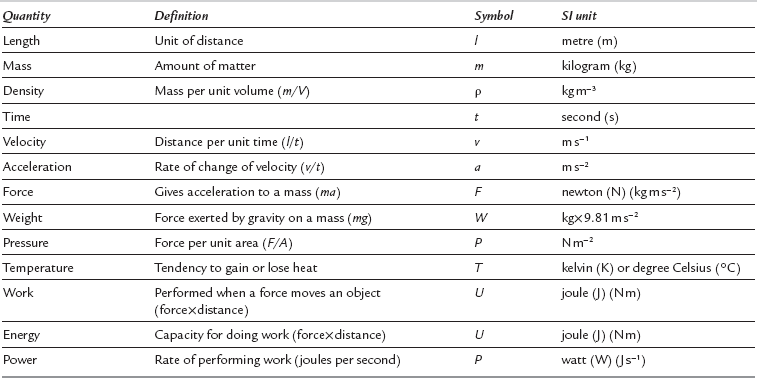
The fundamental quantities in physics are mass, length and time.
From these basic definitions, several units of measurement may be derived:
Density is defined as mass per unit volume:
Velocity is defined as the distance travelled per unit time:
Acceleration is defined as the rate of change of velocity:
Force is that which is required to give a mass acceleration:
Momentum is defined as mass multiplied by velocity:
Work is undertaken when a force moves an object:
Power (P) is the rate of doing work. The SI unit of power is the watt, which is equal to 1 J s− 1:
= joules per second = watt (W)
Pressure is defined as force per unit area:

FLUIDS
Behaviour of Gases
Combining these three gas laws:

where suffixes 1 and 2 represent two conditions different in P, V and T of the gas. Note that where a change of conditions occurs slowly enough for T1 = T2, conditions are said to be isothermal, and the combined gas law could be thought of as another form of Boyle’s law.
Clinical Application of the Gas Laws
Filling Ratio: The degree of filling of a nitrous oxide cylinder is expressed as the mass of nitrous oxide in the cylinder divided by the mass of water that the cylinder could hold. Normally, a cylinder of nitrous oxide is filled to a ratio of 0.67. This should not be confused with the volume of liquid nitrous oxide in a cylinder. A ‘full’ cylinder of nitrous oxide at room temperature is filled to the point at which approximately 90% of the interior of the cylinder is occupied by liquid, the remaining 10% being occupied by nitrous oxide vapour. Incomplete filling of a cylinder is necessary because thermally induced expansion of the liquid in a totally full cylinder may cause cylinder rupture. Because vapour pressure increases with temperature, it is necessary to have a lower filling ratio in tropical climates than in temperate climates.
Entonox: Entonox is the trade name for a compressed gas mixture containing 50% oxygen and 50% nitrous oxide. The mixture is compressed into cylinders containing gas at a pressure of 137 bar (2000 lb in–2) gauge pressure (see below). The nitrous oxide does not liquefy because the two gases in this mixture ‘dissolve’ in each other at high pressure. In other words, the presence of oxygen reduces the critical temperature of nitrous oxide. The critical temperature of the mixture is −7 °C, which is called the ‘pseudocritical temperature’. Cooling of a cylinder of Entonox to a temperature below −7 °C results in separation of liquid nitrous oxide. Use of such a cylinder results in oxygen-rich gas being released initially, followed by a hypoxic nitrous oxide-rich gas. Consequently, it is recommended that when an Entonox cylinder may have been exposed to low temperatures, it should be stored horizontally for a period of not less than 24 h at a temperature of 5 °C or above. In addition, the cylinder should be inverted several times before use.
Pressure Notation in Anaesthesia
Measurement of central venous pressure is sometimes referred to in cm H2O because it can be measured using a manometer filled with saline, but it is more commonly described in mmHg when measured using an electronic transducer system. Note that, although we colloquially speak of ‘cm H2O’ or ‘mmHg’, the actual expression for pressure measured by a column of fluid is P = ρ.g.H, where ρ is fluid density, g is acceleration due to gravity and H is the height of the column. Because mercury is 13.6 times more dense than water, a mercury manometer can measure a given pressure with a much shorter length of column of fluid. For example atmospheric pressure (PB) exerts a pressure sufficient to support a column of mercury of height 760 mm (Fig. 14.1).
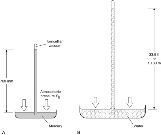
FIGURE 14.1 The simple barometer described by Torricelli (not to scale). (A) Filled with mercury. (B) Filled with water.
GAS REGULATORS
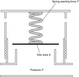
The Heidbrink valve is a common component of many anaesthesia breathing systems. In the Magill breathing system, the anaesthetist may vary the force in the spring(s), thereby controlling the pressure within the breathing system (Fig. 14.2). At equilibrium, the force exerted by the spring is equal to the force exerted by gas within the system:
Pressure-Reducing Valves (Pressure Regulators)
Pressure regulators have two important functions in anaesthetic machines:
 They reduce high pressures of compressed gases to manageable levels (acting as pressure-reducing valves).

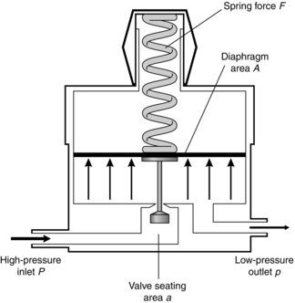
The principle on which the simplest type of pressure-reducing valve operates is shown in Figure 14.3. High-pressure gas enters through the valve and forces the flexible diaphragm upwards, tending to close the valve and prevent further ingress of gas from the high-pressure source.

Pressure Demand Regulators
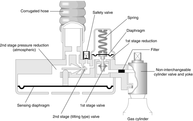
These are regulators in which gas flow occurs when an inspiratory effort is applied to the outlet port. The Entonox valve is a two-stage regulator and its mode of action is demonstrated in Figure 14.4. The first stage is identical to the reducing valve described above. The second-stage valve contains a diaphragm. Movement of this diaphragm tilts a rod, which controls the flow of gas from the first-stage valve. The second stage is adjusted so that gas flows only when pressure is below atmospheric.
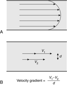
Flow of Fluids

In this context, velocity gradient is equal to the difference between velocities of different fluid layers divided by the distance between layers (Fig. 14.5B). The units of the coefficient of viscosity are Pascal seconds (Pa s).
Laminar Flow
Laminar flow through a tube is illustrated in Figure 14.5A. In this situation, there is a smooth, orderly flow of fluid such that molecules travel with the greatest velocity in the axial stream, whilst the velocity of those in contact with the wall of the tube may be virtually zero. The linear velocity of axial flow is twice the average linear velocity of flow.

 is the flow, ∆P is the pressure gradient along the tube, r is the radius of the tube, η is the viscosity of fluid and l is the length of the tube.
Turbulent Flow: Flow of Fluids Through Orifices
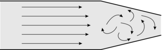
In turbulent flow, fluid no longer moves in orderly planes but swirls and eddies around in a haphazard manner as illustrated in Figure 14.6. Essentially, turbulent flow is less efficient in the transport of fluids because energy is wasted in the eddies, in friction and in noise (bruits). Although viscosity is the important physical variable in relation to the behaviour of fluids in laminar flow, turbulent flow is more markedly affected by changes in fluid density.
It may be seen from Figure 14.7 that the relationship between pressure and flow is linear within certain limits. However, as velocity increases, a point is reached (the critical point or critical velocity) at which the characteristics of flow change from laminar to turbulent. The critical point is dependent upon several factors, which were investigated by the physicist Osborne Reynolds. These factors are related by the formula used for calculation of Reynolds’ number:
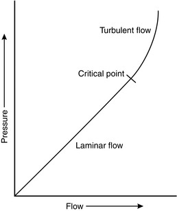
FIGURE 14.7 The relationship between pressure and flow in a fluid is linear up to the critical point, above which flow becomes turbulent.

 the square root of the pressure difference driving the flow


Applications of Turbulence in Anaesthetic Practice:
 In upper respiratory tract obstruction of any severity, flow is inevitably turbulent downstream of the obstruction; thus for the same respiratory effort (driving pressure), a lower tidal volume is achieved than when flow is laminar. The extent of turbulent flow may be reduced by reducing gas density; clinically, it is common practice to administer oxygen-enriched helium rather than oxygen alone (the density of oxygen is 1360 kg m− 3 and that of helium is 160 kg m− 3). This reduces the likelihood of turbulent flow and reduces the respiratory effort required by the patient.

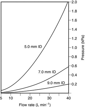
 Resistance to breathing is much greater when a tracheal tube of small diameter is used (Fig. 14.8). Tubes should be of as large a diameter and as short as possible.
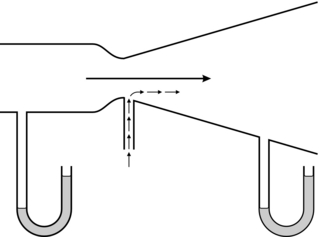
THE VENTURI, THE INJECTOR AND BERNOULLI
assuming that the predominant fluid flow is horizontal such that gravitational potential energy can be ignored.
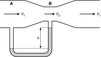
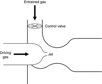
In a venturi, in order that the fluid flow be continuous, its velocity must increase through its narrowed throat (v2 > v1). This is associated with an increase in kinetic energy and Bernoulli’s equation shows that where this occurs, there is an associated reduction in potential energy and therefore in pressure. Beyond the constriction, velocity decreases back to the initial value and the pressure rises again. The principle is illustrated in Figure 14.9. At point A, the energy in the fluid consists of potential (pressure) and kinetic (velocity), but at point B the amount of kinetic energy has increased because of the increased velocity. As the total energy state must remain constant, pressure is reduced at point B. A venturi has a number of uses, including that of a flow measurement device. For optimum performance of a venturi, it is desirable for fluid flow to remain laminar and this is achieved by gradual opening of the tube beyond the constriction. In this way, if a U tube manometer is placed with one limb sampling the pressure at point A and the other at point B, then if the flow remains laminar, Hagen–Poiseuille’s equation suggests a linear relationship between the pressure difference and the flow; this makes calibration of such a flowmeter relatively easy. This contrasts with an orifice, at the outflow of which the flow is usually turbulent. Although an orifice can be used as a flowmeter, the relationship between pressure difference and flow is non-linear. Another use of a venturi is as a device for entraining fluid from without. If a flow of oxygen is fed into a venturi through a nozzle, the low pressure induced at the throat may be used to entrain air, thus giving a metered supply of oxygen-enriched air, or acting as an injector by multiplying the amount of air flowing through the venturi towards the patient’s lungs. If, instead, a hole is made in the side of the venturi at the throat, then the low pressure at that point may form the basis of a suction device (Fig. 14.10).
The injector principle may be seen in anaesthetic practice in the following situations:
 Oxygen therapy. Several types of venturi oxygen masks are available which provide oxygen-enriched air. With an appropriate flow of oxygen (usually exceeding 4 L min–1), there is a large degree of entrainment of air. This results in a total gas flow that exceeds the patient’s peak inspiratory flow rate, thus ensuring that the inspired oxygen concentration remains constant, and it prevents an increase in apparatus dead space which always accompanies the use of low-flow oxygen devices.


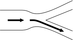
The Coanda Effect
The Coanda effect describes a phenomenon whereby when gas flows through a tube and enters a Y-junction, gas tends to cling either to one side of the tube or to the other. This is because a Y-junction usually implies a reduction in downstream tube diameter, and thus an increase in velocity with a reduction in pressure adjacent to the wall. The gas is often not divided equally between the two outlets. The principle has been used in anaesthetic ventilators (termed fluidic ventilators), as the application of a small pressure distal to the restriction may enable gas flow to be switched (using an external cross flow of gas) from one side to another (Fig. 14.12).
HEAT
Temperature and its Measurement
temperature (K) = temperature (°C) + 273.15
Temperature is measured in clinical practice by one of the following techniques:
 Liquid expansion thermometer. Mercury and alcohol are the more commonly used liquids.


 Chemical thermometers. These thermometers are described in more detail in Chapter 16.


VAPORIZATION AND VAPORIZERS
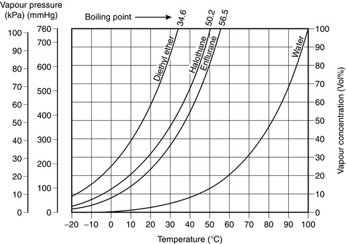
The boiling point of a liquid is the temperature at which its saturated vapour pressure becomes equal to the ambient pressure. Thus, on the graph in Figure 14.13, the boiling point of each liquid at 1 atmosphere is the temperature at which its saturated vapour pressure is 101.3 kPa.
Vaporizers
Vaporizers may be classified into two types:


The principles of both devices are similar. If we consider the simplest form of vaporizer (Fig. 14.14), the concentration (C) of anaesthetic in the gas mixture emerging from the outlet port is dependent upon:
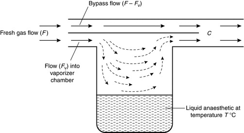
 The saturated vapour pressure of the anaesthetic liquid in the vaporizer. A highly volatile agent such as diethyl ether or desflurane is present in a much higher concentration than a less volatile agent (i.e. with a lower saturated vapour pressure) such as halothane or isoflurane.
 The temperature of the liquid anaesthetic agent, as this determines its saturated vapour pressure.


Back Pressure (Pumping Effect)
Some gas-driven mechanical ventilators (e.g. the Manley ventilator) produce a considerable increase in pressure in the outlet port and back bar of the anaesthetic machine. This pressure is highest during the inspiratory phase of ventilation. If the simple vaporizer shown in Figure 14.14 is attached to the back bar, the increased pressure during inspiration compresses the gas in the vaporizer; some gas in the region of the inlet port of the vaporizer is forced into the vaporizing chamber, where more vapour is added to it. Subsequently, there is a temporary surge in anaesthetic concentration when the pressure decreases at the end of the inspiratory cycle.


HUMIDITY AND HUMIDIFICATION
Absolute and Relative Humidity
In normal practice, relative humidity may be measured using:


SOLUBILITY OF GASES
Diffusion
If two different gases or liquids are separated in a container by an impermeable partition which is then removed, gradual mixing of the two different substances occurs as a result of the kinetic activity of each species of molecule. This is illustrated in Figure 14.15. The principle governing this process is described by Fick’s law of diffusion, which states that the rate of diffusion of a substance across unit area is proportional to the concentration gradient. Graham’s law (which applies to gases only) states that the rate of diffusion of a gas is inversely proportional to the square root of its molecular weight or density.
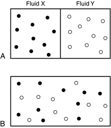
FIGURE 14.15 Illustration of diffusion in fluids. (A) Fluids X and Y separated by partition. (B) Mixing of fluids after removal of partition.
In the example shown in Figure 14.15B, the interface between fluids X and Y immediately after removal of the partition would be the interface between the two species of fluid. In biology, however, there is normally a membrane separating gases or separating gas and liquids.
Osmosis
In the examples given above, the membranes are permeable to all substances. However, in biology, membranes are frequently semipermeable, i.e. they allow the passage of some substances but are impermeable to others. This is illustrated in Figure 14.16. In Figure 14.16A, initially equal volumes of water and glucose solution are separated by a semipermeable membrane. Water molecules pass freely through the membrane to dilute the glucose solution (Fig. 14.16B). This process continues until the volume of the diluted glucose solution supports a significantly greater head of fluid pressure than the water volume on the other side of the membrane. This hydrostatic pressure opposes the flow of water molecules through the membrane into the glucose solution, driven by the difference in solution constituents. This driving pressure is termed the osmotic pressure. Note that, depending on the membrane properties, the glucose molecules are probably too large to allow significant flow in the opposite direction. By application of a hydrostatic pressure on the glucose side (Fig. 14.16C), the process of further transfer of water molecules can be prevented or even reversed; this pressure (P) is equal to the osmotic pressure exerted by the glucose solution.
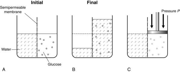
FIGURE 14.16 Diagram to illustrate osmotic pressure. (A) Water and glucose placed into two compartments separated by a semipermeable membrane. (B) At equilibrium, water has passed into the glucose compartment to balance the pressure. (C) The magnitude of osmotic pressure of the glucose is denoted by a hydraulic pressure P applied to the glucose to prevent any movement of water into the glucose compartment.
ELECTRICITY
Electrical Safety
 Class I equipment (fully earthed). The main supply lead has three cores (live, neutral and earth). The earth is connected to all exposed conductive parts, and in the event of a fault developing which short-circuits current to the casing of the equipment, current flows from the case to earth. If small enough, the casing is rendered safe, if large enough the fuse on the live input to the device is blown and the equipment is rendered unusable, but safe.


Diathermy
A diathermy machine is used to pass electric current of high frequency (about 1-2 MHz) through the body in order to cause cutting and/or coagulation by burning local tissue where the current density is high. In the electrical circuit involving diathermy equipment, there are two connections with the patient. In unipolar diathermy, these are the patient plate and the active electrode used by the surgeon (Fig. 14.17A). The current travels from the active electrode, through the patient and exits through the patient plate. The current density is high at the active end where burning or cutting occurs, but it is low at the plate end, where no injury occurs. If for any reason (e.g. a faulty plate) the current flows from the patient through a small area of contact between the patient and earth, then a burn may occur at the point of contact.
In bipolar diathermy, there is no patient plate, but the current travels down one side of the diathermy forceps and out through the other side (Fig. 14.17B). This type of diathermy uses low power and, because the current does not travel through the patient, it is advisable to use this in patients with a cardiac pacemaker.
ISOTOPES AND RADIATION
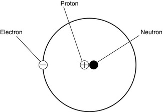
An atom consists of electrons which are negatively charged and these orbit around a nucleus which contains protons (positive charge) and neutrons (no charge) (Fig. 14.18). Isotopes are variations of similar atoms but with different numbers of neutrons. Isotopes with unstable nuclei are known as radioisotopes and are radioactive.
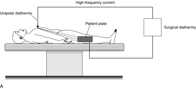
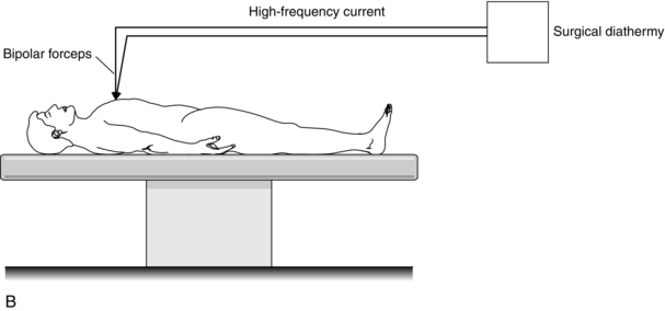
FIGURE 14.17 Principle of the surgical diathermy system. (A) Unipolar diathermy. (B) Bipolar diathermy.
ULTRASOUND
Ultrasonic vibration is defined as between 20 kHz and the MHz range, outside hearing range. An ultrasound probe or transmitter consists of a piezo-electric crystal, which generates mechanical vibration, a vibrating pressure wave, in response to an electrical input (see Fig. 14.19A). Conversely it can also produce an electrical output in response to a mechanical pressure wave input. Hence the piezo-electric crystal can be used to transmit a pressure wave and to detect a reflected wave (see Fig. 14.19B).
The period T of such a wave is the time taken for one full cycle, and is given by T T= 1/f.
Ultrasound velocity in a tissue and the attenuation of the wave varies depending on the tissue it is travelling through. In soft tissues the wave velocity is between 1460 and 1630 m s− 1 whereas in bone it is 2700–4100 m s− 1. Bone attenuates the waveform about 10 times as quickly as soft tissue. The greatest penetration is achieved with the lowest frequency but with poor resolution, while the converse holds for high frequency waves. A compromise is to use the highest frequency that will give good resolution, and which will also ensure adequate penetration of the tissues being investigated. For example, a frequency of 3 MHz is normally used to visualize the kidneys, while 20 MHz is used to visualize intracorporeal devices inserted by the anaesthetist, such as needles and catheters. It is the reflection of the ultrasound wave at the interface between two tissues or at tissue-fluid (air) interfaces which provides a diagnostic image. The same piezo-electric crystal is usually used as the receiver, with the transmission mode switched off. The induced pressure changes coupled to the transducer induce electrical signals, which produce an image (see Fig. 14.19B). A real-time two dimensional image, using multiple probes, can be produced; this is known as a B scan.
For a transmitted frequency ft, of wavelength λ, and the velocity of sound in the medium c:
LASERS
Physical Principles of Lasers
 Excitation: stable atom + energy → high-energy atom
 Spontaneous emission: high-energy atom → stable atom + a photon of light
 Stimulated emission: photon of light + high-energy atom → stable atom + 2 photons of light.
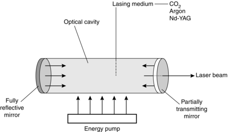
A laser system has four components (Fig. 14.20).
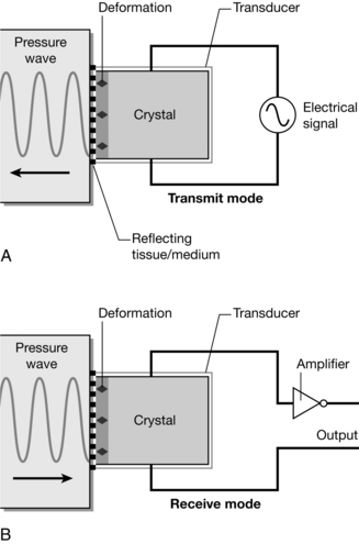
FIGURE 14.19 Ultrasound generated from a piezo-electric crystal. An electrical signal input causes the crystal to deform (A), creating a pressure wave. Air conducts ultrasound poorly, so coupling between probe and surface requires gel. In (B) the reverse process occurs, and a reflected pressure wave induces an electrical signal, which can be used to create an image. (Adapted from Fig: 10.1 ‘Ultrasound and Doppler’ from Magee P, Tooley M (2011) Physics, Clinical Measurement and Equipment of Anaesthetic Practice for the FRCA by permission of Oxford University Press.)


OPTICAL FIBRES
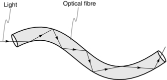
Optical fibres are used in the design of endoscopes and bronchoscopes in order to be able to see around corners. Optical fibres use the principle that when light passes from one medium to another, it is refracted (i.e. bent). If the direction of the light is altered, the light may be totally reflected instead and this allows transmission of the light along the optical fibres (Fig. 14.21). As a result, if light passes into one end of a fibre of glass or other transparent material, it may pass along the fibre by being continually reflected from the glass/air boundary. Endoscopes and bronchoscopes contain bundles of flexible transparent fibres.
FIRES AND EXPLOSIONS


Association of Anaesthetists of Great Britain and Ireland Provision of anaesthetic services in magnetic resonance units. The Association of Anaesthetists of Great Britain and Ireland. 2002. http://www.aagbi.org/publications/guidelines/docs/mri02.pdf.
Association of Anaesthetists of Great Britain and Ireland. Safety in magnetic resonance units: an update. Anaesthesia. 2010;65:766–770.
Davis, P.D., Kenny, G.N.C. Basic physics and measurement in anaesthesia, fifth ed. London: Heinemann; 2003.
Davey, A., Diba, A. Ward’s anaesthetic equipment, fifth ed. London: WB Saunders; 2005.
Magee, P., Tooley, M. The physics, clinical measurement and equipment of anaesthetic practice, second ed. Oxford: Oxford University Press; 2011.