Chapter 7 Basic biomechanics
Movements
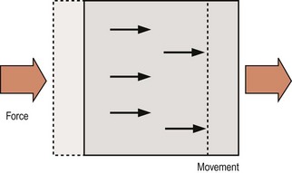
There are two types of motion that a bone may undergo: translation and rotation. The essence of translation is that every point on the bone moves in the same direction and to the same extent (Fig. 7.1). Translation occurs whenever a single force or a net single force acts on a bone, and any force that tends to cause translation is called a shear force.
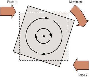
Rotation is characterised by all the points on a bone moving in parallel around a curved path centred on some fixed point. The points move in a similar direction but to different extents depending on their radial distance from the fixed point which is known as the centre of rotation (Fig. 7.2). Rotation occurs when two unaligned forces act in opposing directions on different parts of the bone, forming what is known as a force couple (see Fig. 7.2), and the net force tending to cause rotation is referred to as the torque. Depending on circumstances, torque may be the result of two opposed forces which may both be muscular actions, or they may be a muscular action and a ligamentous resistance, or they may be gravity opposed by either muscular action or ligamentous resistance.
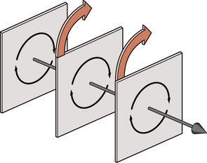
When a rotating bone is considered in three dimensions it can be seen that all the points throughout the bone can be grouped into individual planes that lie parallel to the direction of motion (Fig. 7.3). In each plane, the points move about a centre located in that plane, and when all the centres of all the planes are lined up they depict a straight line that forms what is known as the axis of rotation of the bone.
Planes of movement
Both translation and rotation can occur in either of two opposite senses which can be variously defined according to circumstances or convention. For example, the motion can be upwards or downwards, forwards or backwards, clockwise or anticlockwise, and in some conventions positive (+) or negative (−). Furthermore, in three-dimensional space, translation or rotation can occur in any of three fundamental planes. In anatomical terms, these planes are the sagittal, coronal and horizontal planes (Fig. 7.4). Backward or forward rotations are movements in the sagittal plane, as are translations in the backward or forward direction. Side-bending is rotation in the coronal plane, and twisting is rotation in the horizontal plane. A sideways gliding movement across the horizontal plane would be horizontal translation, while movements up or down are described as coronal translations.
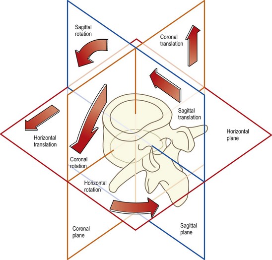
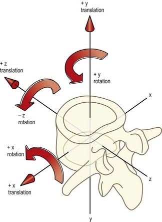
Biomechanists prefer to define movements in relation to three imaginary axes drawn through the body, which are labelled X, Y and Z.1,2 The X axis passes sideways through the body; the Y axis passes through it vertically; and the Z axis passes through it from back to front (Fig. 7.5). Movements can then be described as along or around any particular axis. Thus, sagittal translation is translation along the Z axis; sideways gliding movements are translations along the X axis; and up and down movements are along the Y axis. Forward bending is rotation around the X axis; side-bending is rotation about the Z axis; and twisting movements are rotations around the Y axis. The key to this nomenclature lies in the prepositions used. Translations are movements along one of the axes while rotations are movements around one of the axes.
The advantage of the biomechanists’ convention is that the dimensions of movements are accurately and unambiguously defined. However, the terms ‘X’, ‘Y’ and ‘Z’ are unfamiliar and anonymous to all except to those who use them regularly. The terms ‘sagittal’, ‘coronal’ and ‘horizontal’ are somewhat more meaningful because of their use in other areas of anatomy, and these are the terms used in this text. In the anatomical system the movements are perceived to occur in or along the plane in question, irrespective of whether the movement is a translation or a rotation. For reference, the equivalence of various terms derived from the anatomical system, the biomechanists’ convention and colloquial vocabulary is shown in Table 7.1.
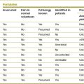
Table 7.1 Descriptive terms of motion. By convention, the direction of any rotation is defined according to the direction of movement of the most anterior point on the bone
| Anatomical system | Biomechanical system | Colloquial description |
|---|---|---|
| Anterior sagittal translation | +Z translation | Forward slide or glide |
| Posterior sagittal translation | −Z translation | Backward slide |
| Cephalad coronal translation | +Y translation | Longitudinal or axial distraction |
| Caudal coronal translation | −Y translation | Longitudinal or axial compression |
| Left horizontal translation | +X translation | Left lateral slide |
| Right horizontal translation | −X translation | Right lateral slide |
| Anterior sagittal rotation | +X rotation | Forward bend, ‘flexion’ |
| Posterior sagittal rotation | −X rotation | Backward bend, ‘extension’ |
| Left coronal rotation | −Z rotation | Left lateral bend |
| Right coronal rotation | +Z rotation | Right lateral bend |
| Left horizontal rotation | +Y rotation | Left axial rotation |
| Right horizontal rotation | −Y rotation | Right axial rotation |
Because of difficulties in appreciating the distinctions between translations and rotations in the horizontal and coronal planes, the term ‘axial’ has been introduced in Table 7.1. Thus, the term ‘axial rotation’ replaces ‘horizontal rotation’ to refer to rotation in the horizontal plane, i.e. around the long axis of the body. The term ‘axial translation’ replaces ‘coronal translation’ to refer to movement up or down, or along the long axis of the body, and to distinguish this movement from sideways translations in the horizontal plane, which are described as horizontal or lateral translations.
To specify the direction of axial translations, the terms ‘cephalad’, meaning towards the head, and ‘caudad’, meaning towards the tail, are used in Table 7.1. Although perhaps cumbersome and unfamiliar, these terms are accurate and applicable in all situations. The more familiar terms ‘upward’ and ‘downward’ are applicable for axial translations in the upright position but they are not strictly applicable in describing motions of vertebrae in patients who might be lying down. To overcome this difficulty, the more colloquial terms of ‘distraction’ and ‘compression’ are more usually used instead of ‘cephalad’ and ‘caudad axial translation’. Similarly, the term ‘lateral bending’ is more convenient and is preferred to ‘coronal rotation’.
In this text, the term ‘sagittal’ rotation is strictly used to refer to forward and backward rotatory movements. Although the terms ‘flexion’ and ‘extension’ are commonly used to describe this motion, these terms are insufficiently accurate when applied to movements of individual lumbar vertebrae. Flexion and extension are not pure movements of the lumbar vertebrae because, as will be shown in Chapter 8, these movements involve a combination of both sagittal translation and sagittal rotation. The terms ‘flexion’ and ‘extension’ may be used to describe forward bending and backward bending of the lumbar spine in a general sense, but in relation to movements of individual vertebrae it should be understood that the terms refer to a combination of both sagittal rotation and sagittal translation.
The relevance of these explicit definitions of motion is extensive. In the first instance, the motion of individual vertebrae is often complex, and no single term can describe the motion. Nevertheless, it can always be described as some combination of the fundamental movements listed in Table 7.1. Furthermore, each component of motion of the lumbar spine is exerted and resisted by different mechanisms, and to appreciate how these mechanisms act, each needs to be analysed in relation to the particular component of motion that it controls. This type of analysis is undertaken in Chapter 8.
Stress–strain
To stretch a collagen fibre, a force must be applied to it. Once it starts to stretch, the fibre resists elongation by generating a resisting force due to the chemical bonds between collagen fibrils, between tropocollagen molecules, between collagen fibres, and between collagen fibres and proteoglycans (see Ch. 2). By convention, the applied or elongating force is known as the applied stress and the extent to which a fibre is elongated is known as the strain. Stress is measured in units of force (newtons) and strain is measured as the fractional or percentage increase in length relative to initial length. Thus a fibre of length L0 when stretched to a new length L1 undergoes a strain of L1/L0 or L1/L0 × 100%.
At rest, single collagen fibres are usually buckled, and the wavy shape they assume is referred to as crimp.3–6 When stress is applied to a collagen fibre, the first effect is to straighten this crimp. Little energy is required to do this as there are no major chemical bonds that maintain it. Thus, a crimped collagen fibre will elongate in response to little applied force. However, once crimp has been removed, the collagen fibre starts to resist strongly any further elongation. The stress attempts to break the bonds between the collagen fibrils and tropocollagen molecules. Energy is required to oppose strain and perhaps eventually to break these bonds. Consequently, more force is required to produce further elongation of the collagen fibre. If sufficient force is applied, the bonds may break, and when this occurs in a substantial number of bonds, the collagen fibre ceases to resist elongation and is said to ‘fail’. Once the collagen fibre has failed, only small forces are required to tear apart its now unbonded component fibrils and molecules.
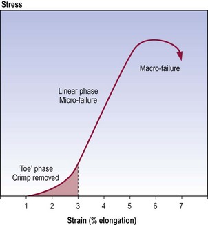
The mechanical behaviour of collagen fibres subject to stress can be depicted graphically,7 as in Figure 7.6; such graphs are known as stress–strain curves. The curve exhibits three main regions. The first region, known as the ‘toe’ phase, reflects the phase when crimp is being removed from the collagen fibre. The second, or linear, region is the steep slope along the middle of the curve. Mathematical calculations reveal that the junction of the toe phase and the linear region represents the point where crimp has been maximally removed from the fibre and the stress starts to stretch the collagen fibre longitudinally.6,7 The linear region represents the phase when bonds within and between collagen fibrils are being strained and some are being broken. The peak of the curve represents the phase of failure of the collagen fibre, when substantial numbers of bonds are irreversibly broken. As depicted by the last part of the curve, once failure has occurred, elongation can continue with ever decreasing amounts of stress being required.
Collagenous tissues, like ligaments and joint capsules, behave in a similar manner to isolated collagen fibres, and exhibit similar stress–strain curves5,6,8,9 but certain additional mechanical events are involved (Fig. 7.7). In addition to the removal of crimp, the toe phase may represent the removal of any macroscopic slack in the ligament. During the second phase, collagen fibres are being rearranged in the stressed structure. Fibres that, at rest, are curved or run obliquely in the three-dimensional lattice of the ligament or capsule are straightened to line up with the applied force. Thus, when the three-dimensional lattice is stressed, any bonds between separate collagen fibres and between collagen fibres and their surrounding proteoglycan matrix are strained. Furthermore, to make way for the rearrangement of collagen fibres, water and proteoglycans may need to be displaced from between the collagen fibres.
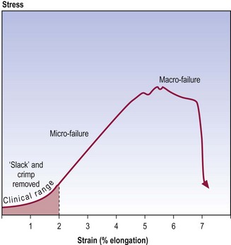
All of these processes require energy: to strain the bonds to move the collagen fibres and proteoglycans; and to squeeze out water. Thus, to achieve continued elongation, more force must be applied and this creates the steep slope of the second phase (see Fig. 7.7). Eventually, after the collagen fibres, proteoglycans and water have been rearranged, the bonds within individual collagen fibres are strained. In the face of increasing stress, these bonds and those between collagen fibres will fail and the entire structure fails.
To a certain extent, physical examination involves obtaining a stress–strain curve for a joint and its capsule or ligaments. When passive movement is induced, a stress is applied, and strain is reflected in terms of both the range of movement observed and the form of the palpated resistance to movement. It is important to realise, however, that clinical examination only studies the early part of the stress–strain curve, no further than just beyond the toe phase.8 The limit is well within the 4% elongation at which microscopic injury occurs. Physical examination rarely (and should not) enter into the second phase, for then it is actually inducing microfailure of the structure, and risks macrofailure. Physical examination therefore gains access to only a part of the total stress–strain curve possible. Nevertheless, it does detect some of the physical properties of the structure examined, which can be interpreted in the light of knowledge of the microstructure and biochemistry of the structure examined, and knowledge of its total mechanical behaviour as determined in cadaveric and post-mortem material.
Stiffness
The stiffness of a given structure is its resistance to deformation and can be measured by the force required to produce a unit elongation or deformation.10 In mathematical terms, it is the slope of the stress–strain curve of a structure. Stiffer structures resist deformation and the slope of their stress–strain curves will be steeper. In biochemical terms, stiffness implies a greater degree of bonding between collagen fibres, or between collagen fibres and their surrounding matrix.
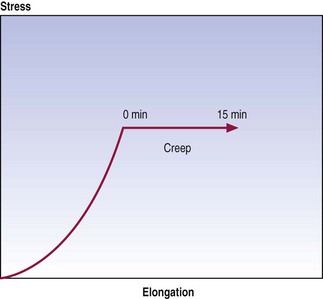
Creep
Graphically, creep is seen as continued displacement when a constant force is maintained at some point on a stress–strain curve (Fig. 7.8). The time over which creep can be measured is optional, and various studies have employed times varying from minutes to hours.10–14
Hysteresis
Most structures, and certainly all biological tissues, exhibit differences in mechanical behaviour during loading versus unloading. Loading produces a characteristic stress–strain curve but gradual release of the load produces a different stress–strain curve. Restoration of the initial length of a ligament occurs at a lesser rate and to a lesser extent than did the deformation (Fig. 7.9). This difference in behaviour is referred to as hysteresis and reflects the amount of energy lost when the structure was initially stressed.
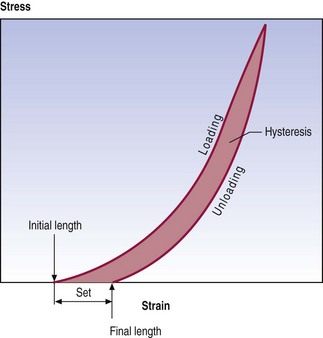
In general, hysteresis and a residual set do not occur if a structure is stressed only in the toe phase of its stress–strain curve, as bonds within and between the collagen fibres are not broken. However, the further a structure is stressed beyond its toe phase, the more bonds are broken and the greater the hysteresis and set.7
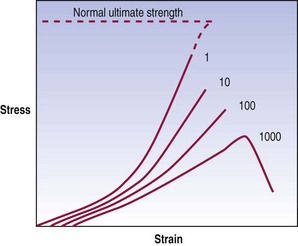
Fatigue failure
This phenomenon is referred to as fatigue failure; its behaviour is illustrated graphically in Figure 7.10. An initial loading reveals the mechanical properties of the material. Its stiffness is evident, and the ultimate tensile stress is the force that would be required to disrupt the material completely upon one application of a force. However, if the material is repeatedly stressed, it exhibits an evolution of mechanical properties. Its stiffness decreases and, in particular, the stress at failure drops. As a result, by repeatedly stressing a material at forces less than those required to break it after one loading, the material can eventually be disrupted. A common analogy is the ability to break a wire or paper clip, not by pulling or bending it once but by repeatedly bending it.
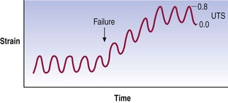
Another way of plotting fatigue failure is to display the evolution of strain over time as a force of constant peak magnitude is applied (Fig. 7.11). The graph shows the repeated cycles of force being applied. Initially, the force applied results in a relatively constant strain but at some point the strain suddenly increases and the specimen operates at a new strain even though the stress has not changed. This behaviour indicates that something in the material has failed, allowing it to exhibit greater deformation for the same stress.
The clinical importance of fatigue failure is that damage to tissues may occur without a history of major or obvious trauma. Indeed, studies of human spinal tissues have shown that an anulus fibrosus typically fails after 3000 repetitions but can fail after as few as 20 repetitions of a force equal to 60% of the ultimate tensile stress.15 Fractures of the vertebral endplate occur within 1000 repetitions but in some cases they occur after as few as 30–80 applications of a stress equal to 50–80% of ultimate compressive strength.16 The forces involved are within the range of those encountered in activities of daily living, and these experimental studies warn that in the face of repetitive loading, elements of the lumbar spine can be injured by forces considerably less than those expected for an acute injury.
Forces and moments
When an object is free to move and is acted upon by a force, it will accelerate in the same direction as the applied force (Fig. 7.12). The force (F) is related to the acceleration (a) by the equation
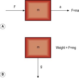

For an object in the Earth’s field of gravity, its weight is produced by the force of gravity trying to accelerate it towards the centre of the Earth (see Fig. 7.12). The mass of the object (m) is related to its weight by the acceleration produced by the Earth’s gravitational field, i.e.
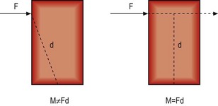
If an object is acted upon by a force but is fixed at some point, the object is not free to move in the direction of the applied force. Instead, it will tend to bend or rotate about the fixed point (Fig. 7.13). A force that causes bending is known as a moment, and its magnitude is proportional to both the magnitude of the force applied and the perpendicular distance between the line of force and the fixed point, i.e.
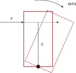
The unit of measure of a moment is newton-metres, the dimensions of which are kg m2 s−2.
It is critical to appreciate that a moment is not calculated according to the distance between the fixed point and the point on the object at which the force is applied. It is calculated according to the perpendicular distance between the fixed point and the direction of the force (Fig. 7.14). This distance is referred to as the moment arm.
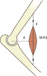
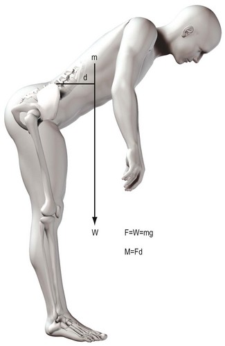
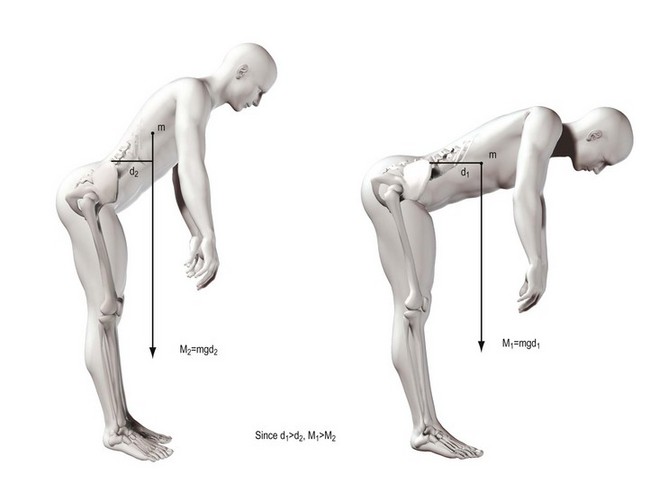
The concept of moments applies to all situations where joints bend, whether they are acted upon by muscles or gravity. The moment generated by a muscle is the product of the force exerted by the muscle and the perpendicular distance between the axis of rotation of the joint and the line of action of the muscle (Fig. 7.15). In the case of the vertebral column, movements such as flexion are frequently exerted by gravity. The force involved is the weight of the trunk leaning forwards of the lumbar spine and it is exerted vertically downwards on the centre of mass of the trunk (Fig. 7.16). The magnitude of the force acting on a given joint in the lumbar spine is calculated as the mass of the trunk above that joint multiplied by g. The moment arm is the perpendicular distance from the joint in question to the line of action of the force (see Fig. 7.16). Clearly, the further a subject leans forward, the longer this moment arm and the greater the resultant moment. Conversely, the more upright a subject stands, the shorter the moment arm and the smaller the flexion moment (Fig. 7.17).
1 White AA, Panjabi MM. Clinical Biomechanics of the Spine. Philadelphia: Lippincott; 1978.
2 White AA, Panjabi MM. The basic kinematics of the human spine. A review of past and current knowledge. Spine. 1978;3:12-20.
3 Diamant J, Keller A, Baer E, et al. Collagen ultrastructure and its relation to mechanical properties as a function of ageing. Proc Roy Soc (series B). 1972;180:293-315.
4 Kirby MC, Sikoryn TA, Hukins DWL, et al. Structure and mechanical properties of the longitudinal ligaments and ligamentum flavum of the spine. J Biomed Eng. 1989;11:192-196.
5 Shah JS. Structure, morphology and mechanics of the lumbar spine. In: Jayson MIV, editor. The Lumbar Spine and Backache. 2nd ed. London: Pitman; 1980:359-405. Ch. 13
6 Shah JS, Jayson MIV, Hampson WGJ. Low tension studies of collagen fibres from ligaments of the human spine. Ann Rheum Dis. 1977;36:139-148.
7 Abrahams M. Mechanical behaviour of tendon in vitro. A preliminary report. Med Biol Eng. 1967;5:433-443.
8 Nordin M, Frankel VH. Biomechanics of collagenous tissues. In: Frankel VH, Nordin M, editors. Basic Biomechanics of the Skeletal System. Philadelphia: Lea & Febiger; 1980:87-110. Ch. 3
9 Noyes FR. Fundamental properties of knee ligaments and alterations induced by immobilization. Clin Orthop. 1977;123:210-242.
10 Twomey L, Taylor J. Flexion creep deformation and hysteresis in the lumbar vertebral column. Spine. 1982;7:116-122.
11 Kazarian LE. Dynamic response characteristics of the human lumbar vertebral column. Acta Orthop Scand. 1972;Suppl(146):1-86.
12 Kazarian LE. Creep characteristics of the human spinal column. Orthop Clin North Am. 1975;6:3-18.
13 Koreska J, Robertson D, Mills RH, et al. Biomechanics of the lumbar spine and its clinical significance. Orthop Clin North Am. 1977;8:121-123.
14 Markolf KL. Deformation of the thoracolumbar intervertebral joints in response to external loads. J Bone Joint Surg. 1972;54A:511-533.
15 Green TP, Adams MA, Dolan P. Tensile properties of the annulus fibrosus II. Ultimate tensile strength and fatigue life. Eur Spine J. 1993;2:209-214.
16 Hansson TH, Keller TS, Spengler DM. Mechanical behaviour of the human lumbar spine. II. Fatigue strength during dynamic compressive loading. J Orthop Res. 1987;5:479-487.